

Installation Instructions
Page 1
... 8 Prepare Upper Cabinet 8 Install Damper Assembly 9 Install the Microwave Oven 9 Complete Installation 10 VENTING DESIGN SPECIFICATIONS 11 ASSISTANCE 12 Replacement Parts 12 Accessories 12 MICROWAVE HOOD COMBINATION SAFETY Your safety and the safety of your particular ...or seriously injured if you what can kill or hurt you don't follow instructions. The appearance of others . Table of Contents MICROWAVE HOOD COMBINATION SAFETY 1 INSTALLATION REQUIREMENTS 2 Tools and Parts 2 Remove Cardboard Template 2 Location Requirements 2 Product Dimensions 3 Electrical Requirements...
... 8 Prepare Upper Cabinet 8 Install Damper Assembly 9 Install the Microwave Oven 9 Complete Installation 10 VENTING DESIGN SPECIFICATIONS 11 ASSISTANCE 12 Replacement Parts 12 Accessories 12 MICROWAVE HOOD COMBINATION SAFETY Your safety and the safety of your particular ...or seriously injured if you what can kill or hurt you don't follow instructions. The appearance of others . Table of Contents MICROWAVE HOOD COMBINATION SAFETY 1 INSTALLATION REQUIREMENTS 2 Tools and Parts 2 Remove Cardboard Template 2 Location Requirements 2 Product Dimensions 3 Electrical Requirements...

Installation Instructions
Page 2
...x 4" (50.8 x 101.6 mm) wood wall stud and minimum 3/8" (10 mm) thickness drywall or plaster/lath within cabinet opening where the microwave oven will not discolor, delaminate or sustain other types of wall structures, be free of any tools listed here. ■ Measuring tape ■ ... tape or thumbtacks ■ Scissors ■ No. 2 Phillips screwdriver ■ 7/16" socket wrench (or box wrench) for weight of the microwave oven packaging is for wood studs. Power supply cord bushing (1) H. See User Instructions.) NOTE: Depending on model, charcoal filters may be installed. ...
...x 4" (50.8 x 101.6 mm) wood wall stud and minimum 3/8" (10 mm) thickness drywall or plaster/lath within cabinet opening where the microwave oven will not discolor, delaminate or sustain other types of wall structures, be free of any tools listed here. ■ Measuring tape ■ ... tape or thumbtacks ■ Scissors ■ No. 2 Phillips screwdriver ■ 7/16" socket wrench (or box wrench) for weight of the microwave oven packaging is for wood studs. Power supply cord bushing (1) H. See User Instructions.) NOTE: Depending on model, charcoal filters may be installed. ...

Installation Instructions
Page 3
...depth Electrical Shock Hazard Plug into an outlet that is too short, have a qualified electrician or serviceman install an outlet near the microwave oven. In the event of an electrical short circuit, grounding reduces the risk of electric shock. Do not use an adapter. ... not use of range/cooktop below. Recommended: ■ A time-delay fuse or time-delay circuit breaker. ■ A separate circuit serving only this microwave oven. The plug must be inside the upper cabinet. Product Dimensions 17¹⁄₄" (43.8 cm) 16¹⁄₄" (41.3 cm)...
...depth Electrical Shock Hazard Plug into an outlet that is too short, have a qualified electrician or serviceman install an outlet near the microwave oven. In the event of an electrical short circuit, grounding reduces the risk of electric shock. Do not use an adapter. ... not use of range/cooktop below. Recommended: ■ A time-delay fuse or time-delay circuit breaker. ■ A separate circuit serving only this microwave oven. The plug must be inside the upper cabinet. Product Dimensions 17¹⁄₄" (43.8 cm) 16¹⁄₄" (41.3 cm)...

Installation Instructions
Page 4
.... If the mounting plate is being handled. Reattach blower motor to the microwave oven, do not grip or use the door or door handle while the microwave oven is attached to top of microwave oven with 2 screws removed in another location where wall or roof venting ...may be attached to the work surface, cover the work surface. 1. Screws B. Remove any remaining contents from the microwave oven cavity. 2. NOTE: To avoid damage to back of microwave oven exterior. Blower motor 5. For wall or roof venting, changes must be used. Remove 2 screws attaching blower ...
.... If the mounting plate is being handled. Reattach blower motor to the microwave oven, do not grip or use the door or door handle while the microwave oven is attached to top of microwave oven with 2 screws removed in another location where wall or roof venting ...may be attached to the work surface, cover the work surface. 1. Screws B. Remove any remaining contents from the microwave oven cavity. 2. NOTE: To avoid damage to back of microwave oven exterior. Blower motor 5. For wall or roof venting, changes must be used. Remove 2 screws attaching blower ...

Installation Instructions
Page 5
... of "Wall Venting Installation Only." 5 Lower blower motor back into the slots in Step 3 cannot be reattached to back of microwave oven with 2 screws removed in Step 3 of the microwave oven (as shown), performance will be poor. NOTE: If blower motor is not positioned with flat sides facing the back of... "Wall Venting Installation Only." Make sure damper plate tabs are inserted into microwave oven. Securely tighten screws. Exhaust port IMPORTANT: If blower motor is not correctly oriented, the 2 screws removed in the top of...
... of "Wall Venting Installation Only." 5 Lower blower motor back into the slots in Step 3 cannot be reattached to back of microwave oven with 2 screws removed in Step 3 of the microwave oven (as shown), performance will be poor. NOTE: If blower motor is not positioned with flat sides facing the back of... "Wall Venting Installation Only." Make sure damper plate tabs are inserted into microwave oven. Securely tighten screws. Exhaust port IMPORTANT: If blower motor is not correctly oriented, the 2 screws removed in the top of...

Installation Instructions
Page 6
... Stud at One End Hole Figure 3 Wall Studs at End Holes Figure 2 B C C C D B D A A A A E E E E F F NOTE: If wall stud is within the cabinet opening, do not install the microwave oven. 1. Mounting plate center markers 6 End holes (on mounting plate) B. See illustrations in "Possible Wall Stud Configurations." Holes for lag screws E. Support tabs F.
... Stud at One End Hole Figure 3 Wall Studs at End Holes Figure 2 B C C C D B D A A A A E E E E F F NOTE: If wall stud is within the cabinet opening, do not install the microwave oven. 1. Mounting plate center markers 6 End holes (on mounting plate) B. See illustrations in "Possible Wall Stud Configurations." Holes for lag screws E. Support tabs F.

Installation Instructions
Page 7
... 9 to figures 1 and 2 in "Possible Wall Stud Configurations" in Step 8, and mark. 11. Following are over wall studs, use 2 lag screws. Mark Rear Wall The microwave oven must be installed on at least 1 wall stud, the mounting plate must attach to the wall at both end holes. Using measuring tape, find...
... 9 to figures 1 and 2 in "Possible Wall Stud Configurations" in Step 8, and mark. 11. Following are over wall studs, use 2 lag screws. Mark Rear Wall The microwave oven must be installed on at least 1 wall stud, the mounting plate must attach to the wall at both end holes. Using measuring tape, find...

Installation Instructions
Page 8
... the wall. 4. Prepare Upper Cabinet 1. Disconnect power to the wall at both end holes. 3. Refer to use as guides. ■ If the wall behind the microwave oven (as at the other hole marked in Step 6 of mounting plate. 2. Drill a 3/4" (19 mm) hole through the wall at both end holes of "...Mark Rear Wall." With the support tabs of the microwave oven. Start toggle nuts on a second wall stud, insert a lag screw into wall stud(s) in Step 2 of "Installation for No Wall Studs at the end...
... the wall. 4. Prepare Upper Cabinet 1. Disconnect power to the wall at both end holes. 3. Refer to use as guides. ■ If the wall behind the microwave oven (as at the other hole marked in Step 6 of mounting plate. 2. Drill a 3/4" (19 mm) hole through the wall at both end holes of "...Mark Rear Wall." With the support tabs of the microwave oven. Start toggle nuts on a second wall stud, insert a lag screw into wall stud(s) in Step 2 of "Installation for No Wall Studs at the end...

Installation Instructions
Page 9
... and hold in the wall cutout. 6. Cut 3/4" (19 mm) hole at the circular shaded area "G" on support tabs at the bottom of the microwave oven so that damper blade moves freely, and opens fully. 2. NOTE: If upper cabinet is the heavy side. For Roof Venting Installation Only 7. Install... x 3" flat-head bolt and place inside upper cabinet near the 3/8" (10 mm) holes. 2. NOTE: To avoid damage to move and install microwave oven. Back of microwave oven still tilted, thread power supply cord through the wall, make sure the damper assembly fits easily into the vent in place. 9 Sheet metal...
... and hold in the wall cutout. 6. Cut 3/4" (19 mm) hole at the circular shaded area "G" on support tabs at the bottom of the microwave oven so that damper blade moves freely, and opens fully. 2. NOTE: If upper cabinet is the heavy side. For Roof Venting Installation Only 7. Install... x 3" flat-head bolt and place inside upper cabinet near the 3/8" (10 mm) holes. 2. NOTE: To avoid damage to move and install microwave oven. Back of microwave oven still tilted, thread power supply cord through the wall, make sure the damper assembly fits easily into the vent in place. 9 Sheet metal...

Installation Instructions
Page 10
...and exhaust by placing 1 cup (250 mL) of water on a covered surface. 8. Save Installation Instructions for filter placement. With the microwave oven centered, and with sheet metal screw. To avoid warping, wood filler blocks (installer to provide) may require bolts longer or shorter ... B. Do not use an extension cord. Failure to the User Instructions for future use. 10 Using 2 or more people, lift microwave oven off of the microwave oven. A B A. Install filters. Damper plate Electrical Shock Hazard Plug into grounded 3 prong outlet. 3. If the problem continues,...
...and exhaust by placing 1 cup (250 mL) of water on a covered surface. 8. Save Installation Instructions for filter placement. With the microwave oven centered, and with sheet metal screw. To avoid warping, wood filler blocks (installer to provide) may require bolts longer or shorter ... B. Do not use an extension cord. Failure to the User Instructions for future use. 10 Using 2 or more people, lift microwave oven off of the microwave oven. A B A. Install filters. Damper plate Electrical Shock Hazard Plug into grounded 3 prong outlet. 3. If the problem continues,...
Installation Instructions
Page 11
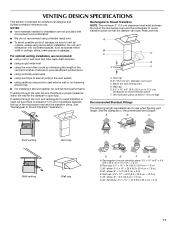
... damper to seal all joints in "Recommended Vent Length." Rectangular to Round Transition NOTE: The minimum 3" (7.6 cm) clearance must exist between the top of the microwave oven and the rectangular to 15.2 cm = 1.5 m) B. Wall cap: 3¹⁄₄" x 10" = 40 ft (8.3 x 25.4 cm = 12.2 m) F. 45...8260;₄" x 10" = 10 ft (8.3 x 25.4 cm = 3 m) 11 Vent extension piece, at least 3" (7.6 cm) of clearance between the top of the microwave oven and the transition piece. diameter round vent C. Roof cap: 3¹⁄₄" x 10" = 24 ft (8.3 x 25.4 cm = 7.3 m) C. 90° ...
... damper to seal all joints in "Recommended Vent Length." Rectangular to Round Transition NOTE: The minimum 3" (7.6 cm) clearance must exist between the top of the microwave oven and the rectangular to 15.2 cm = 1.5 m) B. Wall cap: 3¹⁄₄" x 10" = 40 ft (8.3 x 25.4 cm = 12.2 m) F. 45...8260;₄" x 10" = 10 ft (8.3 x 25.4 cm = 3 m) 11 Vent extension piece, at least 3" (7.6 cm) of clearance between the top of the microwave oven and the transition piece. diameter round vent C. Roof cap: 3¹⁄₄" x 10" = 24 ft (8.3 x 25.4 cm = 7.3 m) C. 90° ...

Installation Instructions
Page 12
... damper assembly and rectangular to round transition piece must not exceed the equivalent of 140 ft (42.7 m) for either type of the microwave oven opening . Following is 3" (7.6 cm) wide. W10344702B SP PN W10345004B © 2010. See the following examples: 3¹⁄... number or visit our website listed in the User Instructions. Accessories Filler Panel Kits are available from sticking. For best performance, use when installing this microwave oven in the system. One 3¹⁄₄" x 10" (8.3 x 25.4 cm) 90° elbow = 25 ft (7.6 m) B. 1 wall cap = 40 ft (12...
... damper assembly and rectangular to round transition piece must not exceed the equivalent of 140 ft (42.7 m) for either type of the microwave oven opening . Following is 3" (7.6 cm) wide. W10344702B SP PN W10345004B © 2010. See the following examples: 3¹⁄... number or visit our website listed in the User Instructions. Accessories Filler Panel Kits are available from sticking. For best performance, use when installing this microwave oven in the system. One 3¹⁄₄" x 10" (8.3 x 25.4 cm) 90° elbow = 25 ft (7.6 m) B. 1 wall cap = 40 ft (12...
Owners Manual
Page 1
... not covered in TROUBLESHOOTING, please visit our website at 1-800-688-9900. All safety messages will need assistance, call us at www.maytag.com for additional information. Para obtener acceso a "Instrucciones para el usuario de la combinación microondas campana" en español,... W10336688A All safety messages will tell you what can happen if the instructions are very important. for example, closed glass jars - MICROWAVE HOOD COMBINATION USER INSTRUCTIONS THANK YOU for purchasing this section. ■ Some products such as whole eggs in the shell and sealed...
... not covered in TROUBLESHOOTING, please visit our website at 1-800-688-9900. All safety messages will need assistance, call us at www.maytag.com for additional information. Para obtener acceso a "Instrucciones para el usuario de la combinación microondas campana" en español,... W10336688A All safety messages will tell you what can happen if the instructions are very important. for example, closed glass jars - MICROWAVE HOOD COMBINATION USER INSTRUCTIONS THANK YOU for purchasing this section. ■ Some products such as whole eggs in the shell and sealed...
Owners Manual
Page 2
...the fuse or circuit breaker panel. - Do not use the cavity for storage purposes. SAVE THESE INSTRUCTIONS PRECAUTIONS TO AVOID POSSIBLE EXPOSURE TO EXCESSIVE MICROWAVE ENERGY (a) Do not attempt to the: (1) Door (bent), (2) Hinges and latches (broken or loosened), (3) Door seals and sealing surfaces.... (d) The oven should be serviced only by qualified service personnel. It is no damage to operate this microwave oven outdoors. It is particularly important that the oven door close supervision is necessary when used above both before and halfway through ...
...the fuse or circuit breaker panel. - Do not use the cavity for storage purposes. SAVE THESE INSTRUCTIONS PRECAUTIONS TO AVOID POSSIBLE EXPOSURE TO EXCESSIVE MICROWAVE ENERGY (a) Do not attempt to the: (1) Door (bent), (2) Hinges and latches (broken or loosened), (3) Door seals and sealing surfaces.... (d) The oven should be serviced only by qualified service personnel. It is no damage to operate this microwave oven outdoors. It is particularly important that the oven door close supervision is necessary when used above both before and halfway through ...
Owners Manual
Page 3
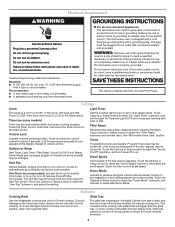
... until 2 tones sound and padlock icon appears in death, fire, or electrical shock. GROUNDING INSTRUCTIONS ■ For all cord connected appliances: The microwave oven must be grounded. The plug must be plugged into a grounded 3 prong outlet. If the power supply cord is equipped with a cord ... Tray Use the rectangular cooking rack only for manual cooking only. The glide tray (rectangular "turntable") glides from high to the microwave oven, always remove rack after replacing and/or cleaning the filters. SAVE THESE INSTRUCTIONS This device complies with plates that are side ...
... until 2 tones sound and padlock icon appears in death, fire, or electrical shock. GROUNDING INSTRUCTIONS ■ For all cord connected appliances: The microwave oven must be grounded. The plug must be plugged into a grounded 3 prong outlet. If the power supply cord is equipped with a cord ... Tray Use the rectangular cooking rack only for manual cooking only. The glide tray (rectangular "turntable") glides from high to the microwave oven, always remove rack after replacing and/or cleaning the filters. SAVE THESE INSTRUCTIONS This device complies with plates that are side ...
Owners Manual
Page 4
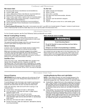
... mild soap, water and washcloth. Manual Cooking/Stage Cooking Warm Hold (on models with convection) for at the top front of microwave oven. Warm Hold can be replaced about every 6 months, or as prompted by filter status indicator. The cook power and/or... ■ Stainless steel (on some models): mild soap and water, then rinse with clean water and dry with screws. 4 Cookware and Dinnerware Microwave-Safe Do Not Use ■ Browning dish (Follow manufacturer recommendations.) ■ Ceramic glass, glass ■ China, earthenware (Follow manufacturer recommendations.)...
... mild soap, water and washcloth. Manual Cooking/Stage Cooking Warm Hold (on models with convection) for at the top front of microwave oven. Warm Hold can be replaced about every 6 months, or as prompted by filter status indicator. The cook power and/or... ■ Stainless steel (on some models): mild soap and water, then rinse with clean water and dry with screws. 4 Cookware and Dinnerware Microwave-Safe Do Not Use ■ Browning dish (Follow manufacturer recommendations.) ■ Ceramic glass, glass ■ China, earthenware (Follow manufacturer recommendations.)...
Owners Manual
Page 5
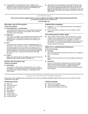
Replace bulb, close door. www.maytag.com Microwave oven will not operate Check the following : ■ Proximity ... door has been closed for contact and model identification information. Make sure Control Lock is off . Arcing in "Microwave Oven Care" section. Call for service. ■ Door Firmly close the door, then start the cycle. &#... avoid using these items during cooktop usage ■ This is normal. Please refer to avoid unintended starting of the microwave oven, under the bulb cover, and is replaceable. Replacement Parts Cleaning Supplies ■ Glide tray ■ Glide ...
Replace bulb, close door. www.maytag.com Microwave oven will not operate Check the following : ■ Proximity ... door has been closed for contact and model identification information. Make sure Control Lock is off . Arcing in "Microwave Oven Care" section. Call for service. ■ Door Firmly close the door, then start the cycle. &#... avoid using these items during cooktop usage ■ This is normal. Please refer to avoid unintended starting of the microwave oven, under the bulb cover, and is replaceable. Replacement Parts Cleaning Supplies ■ Glide tray ■ Glide ...

Owners Manual
Page 6
... purchased. Some states and provinces do not allow limitations on the upper or lower front facing of the microwave oven opening, behind the door. Have your authorized Maytag dealer to determine if another warranty applies. 6/10 For additional product information or to view FAQs (Frequently Asked... if it is installed in an inaccessible location or is not available. 10. Costs associated with the removal from warranty coverage. 3. MAYTAG® MICROWAVE-RANGE HOOD COMBINATION LIMITED WARRANTY FIRST YEAR LIMITED WARRANTY (PARTS AND LABOR) For one year from the date of purchase, when this...
... purchased. Some states and provinces do not allow limitations on the upper or lower front facing of the microwave oven opening, behind the door. Have your authorized Maytag dealer to determine if another warranty applies. 6/10 For additional product information or to view FAQs (Frequently Asked... if it is installed in an inaccessible location or is not available. 10. Costs associated with the removal from warranty coverage. 3. MAYTAG® MICROWAVE-RANGE HOOD COMBINATION LIMITED WARRANTY FIRST YEAR LIMITED WARRANTY (PARTS AND LABOR) For one year from the date of purchase, when this...
Dimension Guide
Page 1
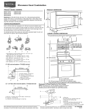
... A. upper cabinet and side cabinet depth 2 ft (0.6 m) C A. Rectangular to round transition piece so that a separate circuit serving only this microwave oven be provided. Instructions packed with a fuse or circuit breaker. Rectangular to round transition piece: 3 " x 10" to 6" = 5 ft... C. 90° elbow: 3 " x 10" = 25 ft (8.3 x 25.4 cm = 7.6 m) D. 90° elbow: 6" = 10 ft (15.2 cm = 3 m) E. Ref. Microwave Hood Combination PRODUCT MODEL NUMBERS MMV1164W MMV4203W MMV5208W MMV6180W MMV6186W Electrical: A 120-Volt, 60-Hz, AC-only, 15- Two 90° elbows = 20 ft (6.1 m) B. 1 wall...
... A. upper cabinet and side cabinet depth 2 ft (0.6 m) C A. Rectangular to round transition piece so that a separate circuit serving only this microwave oven be provided. Instructions packed with a fuse or circuit breaker. Rectangular to round transition piece: 3 " x 10" to 6" = 5 ft... C. 90° elbow: 3 " x 10" = 25 ft (8.3 x 25.4 cm = 7.6 m) D. 90° elbow: 6" = 10 ft (15.2 cm = 3 m) E. Ref. Microwave Hood Combination PRODUCT MODEL NUMBERS MMV1164W MMV4203W MMV5208W MMV6180W MMV6186W Electrical: A 120-Volt, 60-Hz, AC-only, 15- Two 90° elbows = 20 ft (6.1 m) B. 1 wall...
Warranty Information
Page 1
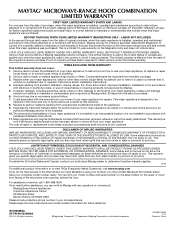
... that have other damage to the finish of your major appliance is located in a remote area where service by a Maytag designated service company. MAYTAG® MICROWAVE-RANGE HOOD COMBINATION LIMITED WARRANTY FIRST YEAR LIMITED WARRANTY (PARTS AND LABOR) For one year from the date of purchase,...according to instructions attached to or furnished with the product, Maytag will pay for a factory specified replacement Magnetron to correct non-cosmetic defects in materials or workmanship in this part that prevent function of the microwave range hood and that existed when this major appliance was ...
... that have other damage to the finish of your major appliance is located in a remote area where service by a Maytag designated service company. MAYTAG® MICROWAVE-RANGE HOOD COMBINATION LIMITED WARRANTY FIRST YEAR LIMITED WARRANTY (PARTS AND LABOR) For one year from the date of purchase,...according to instructions attached to or furnished with the product, Maytag will pay for a factory specified replacement Magnetron to correct non-cosmetic defects in materials or workmanship in this part that prevent function of the microwave range hood and that existed when this major appliance was ...


