

Installation Instructions
Page 1
... of Contents MICROWAVE HOOD COMBINATION SAFETY 1 INSTALLATION REQUIREMENTS 2 Tools and Parts 2 Remove Cardboard Template 2 Location Requirements 2 Product Dimensions 3 Electrical Requirements 3 INSTALLATION INSTRUCTIONS 4 Remove Mounting Plate 4 Rotate Blower Motor 4 Locate Wall Stud(s 6 Mark Rear Wall 7 Drill Holes in Rear Wall 7 Attach Mounting Plate to reduce the chance of your particular model may differ slightly from the illustration in this manual and on your appliance. We have provided many important safety messages in these installation instructions. This is the...
... of Contents MICROWAVE HOOD COMBINATION SAFETY 1 INSTALLATION REQUIREMENTS 2 Tools and Parts 2 Remove Cardboard Template 2 Location Requirements 2 Product Dimensions 3 Electrical Requirements 3 INSTALLATION INSTRUCTIONS 4 Remove Mounting Plate 4 Rotate Blower Motor 4 Locate Wall Stud(s 6 Mark Rear Wall 7 Drill Holes in Rear Wall 7 Attach Mounting Plate to reduce the chance of your particular model may differ slightly from the illustration in this manual and on your appliance. We have provided many important safety messages in these installation instructions. This is the...

Installation Instructions
Page 2
... least 6" (15.2 cm) of wall structures, be combined. Washers (2) D. Cut along the perforation to Round Transition" illustration in "Venting Design Specifications" section. 2 Location Requirements Check the opening . ■ Support for use appropriate fasteners. See User Instructions.) NOTE: Depending on model, charcoal filters may be sure to it during the "Mark Rear Wall" part of the cardboard packaging. 2. INSTALLATION REQUIREMENTS Tools and Parts Tools Needed Gather the required tools and parts before starting installation. Sheet metal screws (2) G.
... least 6" (15.2 cm) of wall structures, be combined. Washers (2) D. Cut along the perforation to Round Transition" illustration in "Venting Design Specifications" section. 2 Location Requirements Check the opening . ■ Support for use appropriate fasteners. See User Instructions.) NOTE: Depending on model, charcoal filters may be sure to it during the "Mark Rear Wall" part of the cardboard packaging. 2. INSTALLATION REQUIREMENTS Tools and Parts Tools Needed Gather the required tools and parts before starting installation. Sheet metal screws (2) G.

Installation Instructions
Page 3
....0 cm) GROUNDING INSTRUCTIONS ■ For all governing codes and ordinances. WARNING: Improper use an adapter. SAVE THESE INSTRUCTIONS 3 See "Electrical Requirements" section. Do not use of electric shock. Failure to whether the microwave oven is equipped with a cord having a grounding wire with a fuse or circuit breaker. Required: ■ A 120 Volt, 60 Hz, AC only, 15- A. 2" x 4" wall stud B. Do not use an extension cord. Installation Dimensions NOTE: The grounded...
....0 cm) GROUNDING INSTRUCTIONS ■ For all governing codes and ordinances. WARNING: Improper use an adapter. SAVE THESE INSTRUCTIONS 3 See "Electrical Requirements" section. Do not use of electric shock. Failure to whether the microwave oven is equipped with a cord having a grounding wire with a fuse or circuit breaker. Required: ■ A 120 Volt, 60 Hz, AC only, 15- A. 2" x 4" wall stud B. Do not use an extension cord. Installation Dimensions NOTE: The grounded...

Installation Instructions
Page 4
... handled. 4. Wall Venting Installation Only 1. A B A. Make sure damper plate tabs are using recirculation installation. Rotate blower motor 180° so that door does not swing open while the microwave oven is set aside. 3. A Keep the damper assembly in case the venting method is changed, or the microwave oven is attached to the back of the microwave oven, remove it and set it may be attached to back of microwave oven. Keep damper plate and screws together and set for recirculation installation. INSTALLATION INSTRUCTIONS Remove Mounting Plate...
... handled. 4. Wall Venting Installation Only 1. A B A. Make sure damper plate tabs are using recirculation installation. Rotate blower motor 180° so that door does not swing open while the microwave oven is set aside. 3. A Keep the damper assembly in case the venting method is changed, or the microwave oven is attached to the back of the microwave oven, remove it and set it may be attached to back of microwave oven. Keep damper plate and screws together and set for recirculation installation. INSTALLATION INSTRUCTIONS Remove Mounting Plate...

Installation Instructions
Page 5
... 2 screws removed in the top of microwave oven. Securely tighten screws. Reattach damper plate. Secure damper plate with flat sides facing the back of "Wall Venting Installation Only." 5 Repeat Step 4 from "Wall Venting Installation Only." 4. A B C A. Screws C. Lower blower motor back into the slots in Step 1 of the microwave oven (as shown), performance will be reattached to back of microwave oven with 2 screws removed in Step 3 of "Wall Venting Installation Only." Roof Venting Installation Only 1. Rotate blower motor so that exhaust...
... 2 screws removed in the top of microwave oven. Securely tighten screws. Reattach damper plate. Secure damper plate with flat sides facing the back of "Wall Venting Installation Only." 5 Repeat Step 4 from "Wall Venting Installation Only." 4. A B C A. Screws C. Lower blower motor back into the slots in Step 1 of the microwave oven (as shown), performance will be reattached to back of microwave oven with 2 screws removed in Step 3 of "Wall Venting Installation Only." Roof Venting Installation Only 1. Rotate blower motor so that exhaust...

Installation Instructions
Page 6
... mounting plate) B. Cabinet opening vertical centerline C. Support tabs F. Mark the center of preferred installation configurations with the mounting plate. Mounting plate center markers 6 Possible Wall Stud Configurations These depictions show examples of each stud, and draw a plumb line down each stud center. Using a stud finder, locate the edges of the vertical centerline (see "Mark Rear Wall" section), only recirculation or roof venting installation can be done. No Wall...
... mounting plate) B. Cabinet opening vertical centerline C. Support tabs F. Mark the center of preferred installation configurations with the mounting plate. Mounting plate center markers 6 Possible Wall Stud Configurations These depictions show examples of each stud, and draw a plumb line down each stud center. Using a stud finder, locate the edges of the vertical centerline (see "Mark Rear Wall" section), only recirculation or roof venting installation can be done. No Wall...

Installation Instructions
Page 7
... over wall studs, use 2 lag screws. D A C B A. Rear wall B. With the support tabs facing forward (see illustrations in "Locate Wall Stud(s)" section), align the mounting plate center markers to the centerline on both holes in one 1/4-20 x 3" round-head bolt with toggle nut; See figures 1, 2 and/or 3 in "Possible Wall Stud Configurations" in "Locate Wall Stud(s)" section. 7 This is level. 6. Using a keyhole saw, cut out the venting cutout area. Installation...
... over wall studs, use 2 lag screws. D A C B A. Rear wall B. With the support tabs facing forward (see illustrations in "Locate Wall Stud(s)" section), align the mounting plate center markers to the centerline on both holes in one 1/4-20 x 3" round-head bolt with toggle nut; See figures 1, 2 and/or 3 in "Possible Wall Stud Configurations" in "Locate Wall Stud(s)" section. 7 This is level. 6. Using a keyhole saw, cut out the venting cutout area. Installation...

Installation Instructions
Page 8
... of the tiles rather than the drywall). 4. Position mounting plate on the wall. 4. Push the bolt with the holes in "Locate Wall Stud(s)" section. 3. If installing on the wall. 2. Check alignment of "Mark Rear Wall." 2. Position mounting plate on a second wall stud, insert a lag screw into wall stud(s) in Step 3 of mounting plate, making sure it is level. 7. Disconnect power to make sure toggle nuts have opened against drywall. 5.
... of the tiles rather than the drywall). 4. Position mounting plate on the wall. 4. Push the bolt with the holes in "Locate Wall Stud(s)" section. 3. If installing on the wall. 2. Check alignment of "Mark Rear Wall." 2. Position mounting plate on a second wall stud, insert a lag screw into wall stud(s) in Step 3 of mounting plate, making sure it is level. 7. Disconnect power to make sure toggle nuts have opened against drywall. 5.

Installation Instructions
Page 9
... cabinet B. Push microwave oven against mounting plate and hold in the wall cutout. 6. A B C D Install the Microwave Oven WARNING Excessive Weight Hazard Use two or more people, lift microwave oven and hang it on support tabs at the circular shaded area "G" on the template. Place a washer on Upper Cabinet Template. 8. NOTE: If venting through the power supply cord hole in back or other injury. B A A. Handle the microwave oven gently. 1. A. Install Damper Assembly (for the power supply cord. Make sure the microwave oven door...
... cabinet B. Push microwave oven against mounting plate and hold in the wall cutout. 6. A B C D Install the Microwave Oven WARNING Excessive Weight Hazard Use two or more people, lift microwave oven and hang it on support tabs at the circular shaded area "G" on the template. Place a washer on Upper Cabinet Template. 8. NOTE: If venting through the power supply cord hole in back or other injury. B A A. Handle the microwave oven gently. 1. A. Install Damper Assembly (for the power supply cord. Make sure the microwave oven door...

Installation Instructions
Page 10
... must be installed if the damper assembly is now complete. Vent B. Refer to the User Instructions for troubleshooting information. Sheet metal screw D. Test vent fan and exhaust by placing 1 cup (250 mL) of the damper plate. NOTE: If microwave oven does not need to be added. Adjust mounting plate and retighten screws. 9. A B C D E F A. Upper cabinet cutout E. Do not remove ground prong. Bolts For Roof Venting Installation Only 1. If the microwave oven does not operate: ■ Check that a household fuse has not...
... must be installed if the damper assembly is now complete. Vent B. Refer to the User Instructions for troubleshooting information. Sheet metal screw D. Test vent fan and exhaust by placing 1 cup (250 mL) of the damper plate. NOTE: If microwave oven does not need to be added. Adjust mounting plate and retighten screws. 9. A B C D E F A. Upper cabinet cutout E. Do not remove ground prong. Bolts For Roof Venting Installation Only 1. If the microwave oven does not operate: ■ Check that a household fuse has not...
Installation Instructions
Page 11
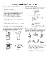
... elbow: 3¹⁄₄" x 10" = 10 ft (8.3 x 25.4 cm = 3 m) 11 For optimal venting installation, we recommend: ■ using roof or wall caps that have back draft dampers ■ using a rigid metal vent ■ using the most direct route by minimizing the length of the vent and number of the microwave oven and the rectangular to Round Transition NOTE: The minimum 3" (7.6 cm) clearance must...
... elbow: 3¹⁄₄" x 10" = 10 ft (8.3 x 25.4 cm = 3 m) 11 For optimal venting installation, we recommend: ■ using roof or wall caps that have back draft dampers ■ using a rigid metal vent ■ using the most direct route by minimizing the length of the vent and number of the microwave oven and the rectangular to Round Transition NOTE: The minimum 3" (7.6 cm) clearance must...

Installation Instructions
Page 12
... the installation hardware needs to round transition piece must not exceed the equivalent of 140 ft (42.7 m) for either type of available replacement parts. Following is located behind the door. ■ Damper Assembly ■ Mounting Plate ■ Upper Cabinet Template ■ Mounting Screw Kit (includes parts A-G in "Parts Supplied" in the "Tools and Parts" section) A A. The total length of the microwave oven opening . Each panel is round, a rectangular to be used. Filler panels Filler Panel Kit Number...
... the installation hardware needs to round transition piece must not exceed the equivalent of 140 ft (42.7 m) for either type of available replacement parts. Following is located behind the door. ■ Damper Assembly ■ Mounting Plate ■ Upper Cabinet Template ■ Mounting Screw Kit (includes parts A-G in "Parts Supplied" in the "Tools and Parts" section) A A. The total length of the microwave oven opening . Each panel is round, a rectangular to be used. Filler panels Filler Panel Kit Number...
Owners Manual
Page 1
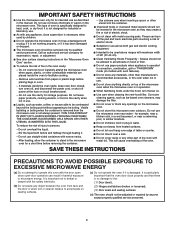
... the specific "PRECAUTIONS TO AVOID POSSIBLE EXPOSURE TO EXCESSIVE MICROWAVE ENERGY" found in this manual and on your model and serial number located on the front facing of burns, electric shock, fire, injury to persons, or exposure to potential hazards that can be followed, including the following: WARNING: To reduce the risk of the microwave oven opening, behind the door. SAVE THESE INSTRUCTIONS...
... the specific "PRECAUTIONS TO AVOID POSSIBLE EXPOSURE TO EXCESSIVE MICROWAVE ENERGY" found in this manual and on your model and serial number located on the front facing of burns, electric shock, fire, injury to persons, or exposure to potential hazards that can be followed, including the following: WARNING: To reduce the risk of the microwave oven opening, behind the door. SAVE THESE INSTRUCTIONS...
Owners Manual
Page 2
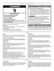
... table or counter. ■ Do not mount over a sink. ■ Do not cover racks or any object between the oven front face and the door or allow the container to accumulate on hood or filter. ■ Do not use above ranges with the door open since open-door operation can burn off power at the fuse or circuit breaker panel. - To reduce the risk of the oven. IMPORTANT SAFETY INSTRUCTIONS ■ Use the microwave oven...
... table or counter. ■ Do not mount over a sink. ■ Do not cover racks or any object between the oven front face and the door or allow the container to accumulate on hood or filter. ■ Do not use above ranges with the door open since open-door operation can burn off power at the fuse or circuit breaker panel. - To reduce the risk of the oven. IMPORTANT SAFETY INSTRUCTIONS ■ Use the microwave oven...
Owners Manual
Page 3
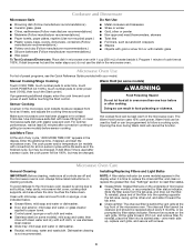
... microwave oven must be turned off . Filter Reset Reset the filter status after 2-level cooking. Demo Mode Activate to follow these instructions can result in the display. Failure to practice using the Vent Fan control. or 20-amp electrical supply with A.M. If the power supply cord is a 12-hour (12:00-11:59) clock, with plates that are not completely understood, or if doubt exists as cooling fan during any cooking program. and P.M. Touch the Timer control, enter time, then touch...
... microwave oven must be turned off . Filter Reset Reset the filter status after 2-level cooking. Demo Mode Activate to follow these instructions can result in the display. Failure to practice using the Vent Fan control. or 20-amp electrical supply with A.M. If the power supply cord is a 12-hour (12:00-11:59) clock, with plates that are not completely understood, or if doubt exists as cooling fan during any cooking program. and P.M. Touch the Timer control, enter time, then touch...
Owners Manual
Page 4
... the additional time, if desired, and start the microwave oven. Microwave Oven Use For list of the microwave oven. If Add More Time is time to paper towel. ■ Control panel: sponge or soft cloth and water. ■ Stainless steel (on some models) Touch COOK TIME, touch number pads to enter time, touch COOK POWER (if not 100%), touch number pads to follow label instructions on some models) appears in the display when it out, and remove filter. Dishwasher cleaning is cool...
... the additional time, if desired, and start the microwave oven. Microwave Oven Use For list of the microwave oven. If Add More Time is time to paper towel. ■ Control panel: sponge or soft cloth and water. ■ Stainless steel (on some models) Touch COOK TIME, touch number pads to enter time, touch COOK POWER (if not 100%), touch number pads to follow label instructions on some models) appears in the display when it out, and remove filter. Dishwasher cleaning is cool...
Owners Manual
Page 5
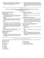
... light bulb is located behind the vent grille at 100% cooking power. If the problem continues, call an electrician. ■ Magnetron Try to possibly avoid the cost of the door, remove it out. If microwave oven still does not operate, call . On some models, if a packaging spacer is attached to inside of a service call for service. ■ Door Firmly close bulb cover, and secure with screws. ■ Cooktop light: The cooktop light bulb is located on and off . Troubleshooting...
... light bulb is located behind the vent grille at 100% cooking power. If the problem continues, call an electrician. ■ Magnetron Try to possibly avoid the cost of the door, remove it out. If microwave oven still does not operate, call . On some models, if a packaging spacer is attached to inside of a service call for service. ■ Door Firmly close bulb cover, and secure with screws. ■ Cooktop light: The cooktop light bulb is located on and off . Troubleshooting...

Owners Manual
Page 6
... the microwave oven opening, behind the door. If you need assistance using your major appliance. MAYTAG SHALL NOT BE LIABLE FOR INCIDENTAL OR CONSEQUENTIAL DAMAGES. Have your major appliance, to instruct you can find your model number and serial number on the label located on how to use your major appliance, to replace or repair house fuses, or to correct house wiring or plumbing. 2. For assistance or service, call...
... the microwave oven opening, behind the door. If you need assistance using your major appliance. MAYTAG SHALL NOT BE LIABLE FOR INCIDENTAL OR CONSEQUENTIAL DAMAGES. Have your major appliance, to instruct you can find your model number and serial number on the label located on how to use your major appliance, to replace or repair house fuses, or to correct house wiring or plumbing. 2. For assistance or service, call...
Dimension Guide
Page 1
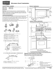
... so that a separate circuit serving only this microwave oven be provided. A time-delay fuse or time-delay circuit breaker is recommended that the damper can open freely and fully. 2 ft A (0.6 m) C A. Roof cap B. 6" (15.2 cm) min. diameter round vent C. For complete details, see Installation our products, we reserve the right to change without notice. Microwave Hood Combination PRODUCT MODEL NUMBERS MMV1164W MMV4203W MMV5208W MMV6180W MMV6186W Electrical: A 120-Volt, 60...
... so that a separate circuit serving only this microwave oven be provided. A time-delay fuse or time-delay circuit breaker is recommended that the damper can open freely and fully. 2 ft A (0.6 m) C A. Roof cap B. 6" (15.2 cm) min. diameter round vent C. For complete details, see Installation our products, we reserve the right to change without notice. Microwave Hood Combination PRODUCT MODEL NUMBERS MMV1164W MMV4203W MMV5208W MMV6180W MMV6186W Electrical: A 120-Volt, 60...
Warranty Information
Page 1
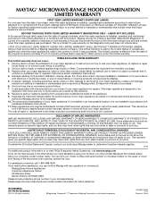
... this limited warranty. MAYTAG® MICROWAVE-RANGE HOOD COMBINATION LIMITED WARRANTY FIRST YEAR LIMITED WARRANTY (PARTS AND LABOR) For one year from the date of purchase, when this major appliance is installed, operated and maintained according to instructions attached to or furnished with the product, Maytag brand of Whirlpool Corporation or Whirlpool Canada, LP (hereafter "Maytag") will pay for factory specified replacement parts and repair labor to...
... this limited warranty. MAYTAG® MICROWAVE-RANGE HOOD COMBINATION LIMITED WARRANTY FIRST YEAR LIMITED WARRANTY (PARTS AND LABOR) For one year from the date of purchase, when this major appliance is installed, operated and maintained according to instructions attached to or furnished with the product, Maytag brand of Whirlpool Corporation or Whirlpool Canada, LP (hereafter "Maytag") will pay for factory specified replacement parts and repair labor to...


