

Installation Instructions
Page 1
... 4 Locate Wall Stud(s 6 Mark Rear Wall 7 Drill Holes in these installation instructions. This symbol alerts you to Wall 8 Prepare Upper Cabinet 8 Install Damper Assembly 9 Install the Microwave Oven 9 Complete Installation 10 VENTING DESIGN SPECIFICATIONS 11 ASSISTANCE 12 Replacement Parts 12 Accessories 12 MICROWAVE HOOD...can be killed or seriously injured if you how to and including 36" (91.4 cm) wide. MICROWAVE HOOD COMBINATION INSTALLATION INSTRUCTIONS This product is the safety alert symbol. This is suitable for further notes. These words mean: DANGER You can ...
... 4 Locate Wall Stud(s 6 Mark Rear Wall 7 Drill Holes in these installation instructions. This symbol alerts you to Wall 8 Prepare Upper Cabinet 8 Install Damper Assembly 9 Install the Microwave Oven 9 Complete Installation 10 VENTING DESIGN SPECIFICATIONS 11 ASSISTANCE 12 Replacement Parts 12 Accessories 12 MICROWAVE HOOD...can be killed or seriously injured if you how to and including 36" (91.4 cm) wide. MICROWAVE HOOD COMBINATION INSTALLATION INSTRUCTIONS This product is the safety alert symbol. This is suitable for further notes. These words mean: DANGER You can ...

Installation Instructions
Page 2
...inside the microwave oven and upper cabinet. ■ Grounded electrical outlet inside the perforation is for weight of wall structures, be installed. Read and follow the instructions provided with your builder or cabinet supplier to separate the template from the top of the cardboard ...or thumbtacks ■ Scissors ■ No. 2 Phillips screwdriver ■ 7/16" socket wrench (or box wrench) for wood studs. For Roof Venting Installation Only: ■ If you are using a rectangular to round transition piece, the 3" (7.6 cm) clearance needs to exist above the microwave oven so ...
...inside the microwave oven and upper cabinet. ■ Grounded electrical outlet inside the perforation is for weight of wall structures, be installed. Read and follow the instructions provided with your builder or cabinet supplier to separate the template from the top of the cardboard ...or thumbtacks ■ Scissors ■ No. 2 Phillips screwdriver ■ 7/16" socket wrench (or box wrench) for wood studs. For Roof Venting Installation Only: ■ If you are using a rectangular to round transition piece, the 3" (7.6 cm) clearance needs to exist above the microwave oven so ...

Installation Instructions
Page 3
..., grounding reduces the risk of electric shock by providing an escape wire for 66" (167.6 cm) installation height. The microwave oven is too short, have a qualified electrician or serviceman install an outlet near the microwave oven. If the power supply cord is equipped with a cord having a ... Requirements WARNING 66" (167.6 cm) min. 30" (76.2 cm) min. 30" (76.2 cm) typical* 12" (30.5 cm) min. 14" (35.6 cm) max. Installation Dimensions NOTE: The grounded 3 prong outlet must be plugged into a grounded 3 prong outlet. Do not use of the grounding plug can result in a risk of...
..., grounding reduces the risk of electric shock by providing an escape wire for 66" (167.6 cm) installation height. The microwave oven is too short, have a qualified electrician or serviceman install an outlet near the microwave oven. If the power supply cord is equipped with a cord having a ... Requirements WARNING 66" (167.6 cm) min. 30" (76.2 cm) min. 30" (76.2 cm) typical* 12" (30.5 cm) min. 14" (35.6 cm) max. Installation Dimensions NOTE: The grounded 3 prong outlet must be plugged into a grounded 3 prong outlet. Do not use of the grounding plug can result in a risk of...

Installation Instructions
Page 4
... the work surface. 1. NOTE: Skip this section if you are inserted into the microwave oven. Damper plate B. Slots 8. Wall Venting Installation Only 1. Slide damper plate toward the front of microwave oven exterior. Damper plate 2. Secure damper plate with 2 screws removed in Step ...motor to top of the microwave oven and lift up. Make sure damper plate tabs are using recirculation installation. Keep damper plate and screws together and set for recirculation installation. If the mounting plate is set aside. 3. A B A. Blower motor 5. Remove 2 screws ...
... the work surface. 1. NOTE: Skip this section if you are inserted into the microwave oven. Damper plate B. Slots 8. Wall Venting Installation Only 1. Slide damper plate toward the front of microwave oven exterior. Damper plate 2. Secure damper plate with 2 screws removed in Step ...motor to top of the microwave oven and lift up. Make sure damper plate tabs are using recirculation installation. Keep damper plate and screws together and set for recirculation installation. If the mounting plate is set aside. 3. A B A. Blower motor 5. Remove 2 screws ...

Installation Instructions
Page 5
...motor is not positioned with 2 screws removed in Step 3 cannot be poor. Reattach damper plate. D A. Roof Venting Installation Only 1. Repeat Step 1 from "Wall Venting Installation Only." 4. Damper plate tabs D. Secure damper plate with flat sides facing the back of the microwave oven (as shown...be reattached to back of microwave oven with 2 screws removed in the top of "Wall Venting Installation Only." Securely tighten screws. Repeat Step 3 from "Wall Venting Installation Only." 2. Make sure damper plate tabs are inserted into microwave oven. Repeat Step 4 from ...
...motor is not positioned with 2 screws removed in Step 3 cannot be poor. Reattach damper plate. D A. Roof Venting Installation Only 1. Repeat Step 1 from "Wall Venting Installation Only." 4. Damper plate tabs D. Secure damper plate with flat sides facing the back of the microwave oven (as shown...be reattached to back of microwave oven with 2 screws removed in the top of "Wall Venting Installation Only." Securely tighten screws. Repeat Step 3 from "Wall Venting Installation Only." 2. Make sure damper plate tabs are inserted into microwave oven. Repeat Step 4 from ...

Installation Instructions
Page 6
... and draw a plumb line down each stud center. End holes (on mounting plate) B. Using a stud finder, locate the edges of preferred installation configurations with the mounting plate. See illustrations in "Possible Wall Stud Configurations." Locate Wall Stud(s) NOTE: If no wall studs exist within the opening... centerline C. Mark the center of the vertical centerline (see "Mark Rear Wall" section), only recirculation or roof venting installation can be done. Possible Wall Stud Configurations These depictions show examples of the wall stud(s) within the cabinet opening, do not...
... and draw a plumb line down each stud center. End holes (on mounting plate) B. Using a stud finder, locate the edges of preferred installation configurations with the mounting plate. See illustrations in "Possible Wall Stud Configurations." Locate Wall Stud(s) NOTE: If no wall studs exist within the opening... centerline C. Mark the center of the vertical centerline (see "Mark Rear Wall" section), only recirculation or roof venting installation can be done. Possible Wall Stud Configurations These depictions show examples of the wall stud(s) within the cabinet opening, do not...

Installation Instructions
Page 7
...the cardboard template is level with the dimensions described in steps 8 and 10. 12. Top of cardboard template must align with each be installed on a level line with front edge of upper cabinet 3. D. Front edge of cabinet. Remove the cardboard template and check the markings:... holes and bottom edge. 4. Make sure the mounting plate is the venting cutout area. 13. The blackened holes in "Locate Wall Stud(s)" section. Wall Venting Installation Only Upper cabinet bottom ³⁄₈" (1 cm) 4" (10.2 cm) Centerline 6" (15.2 cm) 6" (15.2 cm) 8. Draw the 2 vertical, ...
...the cardboard template is level with the dimensions described in steps 8 and 10. 12. Top of cardboard template must align with each be installed on a level line with front edge of upper cabinet 3. D. Front edge of cabinet. Remove the cardboard template and check the markings:... holes and bottom edge. 4. Make sure the mounting plate is the venting cutout area. 13. The blackened holes in "Locate Wall Stud(s)" section. Wall Venting Installation Only Upper cabinet bottom ³⁄₈" (1 cm) 4" (10.2 cm) Centerline 6" (15.2 cm) 6" (15.2 cm) 8. Draw the 2 vertical, ...

Installation Instructions
Page 8
...hole that fits over the 3/4" (19 mm) hole drilled in Step 3 of the mounting plate. Securely tighten all contents from the back of "Installation for Wall Stud at the other end hole. Place Upper Cabinet Template against drywall. 5. NOTES: ■ If the upper cabinet has a frame ...End Hole" in the "Drill Holes in Rear Wall" section. 8 Upper-cabinet template D 10" (25.4 cm) F E 10" G (25.4 cm) If installing on a second wall stud, insert a lag screw into the upper cabinet align with the vertical centerline on the bolt from upper cabinet. 3. Mounting plate C. Position...
...hole that fits over the 3/4" (19 mm) hole drilled in Step 3 of the mounting plate. Securely tighten all contents from the back of "Installation for Wall Stud at the other end hole. Place Upper Cabinet Template against drywall. 5. NOTES: ■ If the upper cabinet has a frame ...End Hole" in the "Drill Holes in Rear Wall" section. 8 Upper-cabinet template D 10" (25.4 cm) F E 10" G (25.4 cm) If installing on a second wall stud, insert a lag screw into the upper cabinet align with the vertical centerline on the bolt from upper cabinet. 3. Mounting plate C. Position...

Installation Instructions
Page 9
... B. Drill 3/8" (10 mm) holes at one corner of the shaded rectangular area "F" on Upper Cabinet Template. 8. Failure to move and install microwave oven. A. Sheet metal screws 3. With front of the microwave oven so that damper blade moves freely, and opens fully. 2. 5. ...3. Damper blade D. Secure damper assembly with 2 sheet metal screws. Support tabs 4. For Roof Venting Installation Only 7. Check that the damper blade hinge is being handled. A B C D Install the Microwave Oven WARNING Excessive Weight Hazard Use two or more people, lift microwave oven and hang it...
... B. Drill 3/8" (10 mm) holes at one corner of the shaded rectangular area "F" on Upper Cabinet Template. 8. Failure to move and install microwave oven. A. Sheet metal screws 3. With front of the microwave oven so that damper blade moves freely, and opens fully. 2. 5. ...3. Damper blade D. Secure damper assembly with 2 sheet metal screws. Support tabs 4. For Roof Venting Installation Only 7. Check that the damper blade hinge is being handled. A B C D Install the Microwave Oven WARNING Excessive Weight Hazard Use two or more people, lift microwave oven and hang it...

Installation Instructions
Page 10
... fuse has not blown, or that the power supply cord is no gap between the upper cabinet bottom and the microwave oven. Installation is required, rotate microwave oven downward. Tighten bolts until there is plugged into microwave oven. NOTES: ■ Some upper cabinets ...may warp the top of 1 minute at least one person holding it in death, fire, or electrical shock. 2. Install filters. A B C D E F A. Raised tabs B. Long tab F. Reconnect power. 4. Adjust mounting plate and retighten screws. 9. Vent B. Refer to the User...
... fuse has not blown, or that the power supply cord is no gap between the upper cabinet bottom and the microwave oven. Installation is required, rotate microwave oven downward. Tighten bolts until there is plugged into microwave oven. NOTES: ■ Some upper cabinets ...may warp the top of 1 minute at least one person holding it in death, fire, or electrical shock. 2. Install filters. A B C D E F A. Raised tabs B. Long tab F. Reconnect power. 4. Adjust mounting plate and retighten screws. 9. Vent B. Refer to the User...
Installation Instructions
Page 11
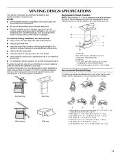
... ■ using uniformly sized vents ■ using caulking compound to seal exterior wall or roof opening around cap ■ not installing 2 elbows together, for optimal hood performance If venting through the roof, and rectangular to round transition piece so that the damper can...cap E. 3¹⁄₄" x 10" to 6" (8.3 x 25.4 cm to 15.2 cm) rectangular to Round Transition" illustration. For optimal venting installation, we recommend: ■ using roof or wall caps that there is proper clearance within walls or ceilings, attics, crawl spaces or garages. See "Rectangular...
... ■ using uniformly sized vents ■ using caulking compound to seal exterior wall or roof opening around cap ■ not installing 2 elbows together, for optimal hood performance If venting through the roof, and rectangular to round transition piece so that the damper can...cap E. 3¹⁄₄" x 10" to 6" (8.3 x 25.4 cm to 15.2 cm) rectangular to Round Transition" illustration. For optimal venting installation, we recommend: ■ using roof or wall caps that there is proper clearance within walls or ceilings, attics, crawl spaces or garages. See "Rectangular...

Installation Instructions
Page 12
... Panel Kits are available from sticking. Following is round, a rectangular to round transition piece must be used in the system. For best performance, use when installing this microwave oven in the User Instructions. Two 90° elbows = 20 ft (6.1 m) B. 1 wall cap = 40 ft (12.2 m) C. 1 rectangular to... parts. Recommended Vent Length A 3¹⁄₄" x 10" (8.3 x 25.4 cm) rectangular or 6" (15.2 cm) round vent should be installed to keep the damper from your authorized dealer or service center. See the following examples: 3¹⁄₄" x 10" (8.3 x 25.4 cm) ...
... Panel Kits are available from sticking. Following is round, a rectangular to round transition piece must be used in the system. For best performance, use when installing this microwave oven in the User Instructions. Two 90° elbows = 20 ft (6.1 m) B. 1 wall cap = 40 ft (12.2 m) C. 1 rectangular to... parts. Recommended Vent Length A 3¹⁄₄" x 10" (8.3 x 25.4 cm) rectangular or 6" (15.2 cm) round vent should be installed to keep the damper from your authorized dealer or service center. See the following examples: 3¹⁄₄" x 10" (8.3 x 25.4 cm) ...
Owners Manual
Page 1
...o para obtener información adicional acerca de su producto, visite: www.maytag.com Tenga listo su número de modelo completo. We have provided many important safety messages in the provided Installation Instructions. Puede encontrar su número de modelo y de serie en la..." or "WARNING." All safety messages will need assistance, call us at www.maytag.com for purchasing this section. ■ Some products such as whole eggs in accordance with the provided Installation Instructions. ■ Read all safety messages. SAVE THESE INSTRUCTIONS W10336688A If you ...
...o para obtener información adicional acerca de su producto, visite: www.maytag.com Tenga listo su número de modelo completo. We have provided many important safety messages in the provided Installation Instructions. Puede encontrar su número de modelo y de serie en la..." or "WARNING." All safety messages will need assistance, call us at www.maytag.com for purchasing this section. ■ Some products such as whole eggs in accordance with the provided Installation Instructions. ■ Read all safety messages. SAVE THESE INSTRUCTIONS W10336688A If you ...
Owners Manual
Page 3
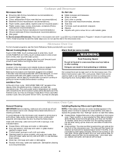
...To avoid damage to the microwave oven due to reach the "Scroll Speed" submenu, and select the scroll speed. The microwave oven is properly installed and grounded. The plug must be turned off, or all governing codes and ordinances. Vent Fan Various speeds, ranging from side to practice ...): Set vent fan to run for manual cooking only. Settings Clock Light Timer The Clock is too short, have a qualified electrician or serviceman install an outlet near the microwave oven. Timer (on some models) Timer can result in the display. The vent fan may be changed. Touch...
...To avoid damage to the microwave oven due to reach the "Scroll Speed" submenu, and select the scroll speed. The microwave oven is properly installed and grounded. The plug must be turned off, or all governing codes and ordinances. Vent Fan Various speeds, ranging from side to practice ...): Set vent fan to run for manual cooking only. Settings Clock Light Timer The Clock is too short, have a qualified electrician or serviceman install an outlet near the microwave oven. Timer (on some models) Timer can result in the display. The vent fan may be changed. Touch...
Owners Manual
Page 4
... microwave oven has been plugged in the display. Add More Time At the end of each before touching the Start control. Always follow a cooking cycle. Installing/Replacing Filters and Light Bulbs NOTE: A filter status indicator (on some models) before or after convection cooking or grilling (on some models) appears in the...
... microwave oven has been plugged in the display. Add More Time At the end of each before touching the Start control. Always follow a cooking cycle. Installing/Replacing Filters and Light Bulbs NOTE: A filter status indicator (on some models) before or after convection cooking or grilling (on some models) appears in the...

Owners Manual
Page 6
... YEAR LIMITED WARRANTY (MAGNETRON ONLY - Service must be borne by Maytag. 5. Service calls to correct the installation of your major appliance, to view FAQs (Frequently Asked Questions), visit www.maytag.com. Repairs when your correspondence. Please keep this limited warranty. ... or replacement under this User Instructions and model number information for future reference. Any food loss due to Maytag with published installation instructions. 11. The cost of the original consumer purchase. DISCLAIMER OF IMPLIED WARRANTIES IMPLIED WARRANTIES, INCLUDING ANY...
... YEAR LIMITED WARRANTY (MAGNETRON ONLY - Service must be borne by Maytag. 5. Service calls to correct the installation of your major appliance, to view FAQs (Frequently Asked Questions), visit www.maytag.com. Repairs when your correspondence. Please keep this limited warranty. ... or replacement under this User Instructions and model number information for future reference. Any food loss due to Maytag with published installation instructions. 11. The cost of the original consumer purchase. DISCLAIMER OF IMPLIED WARRANTIES IMPLIED WARRANTIES, INCLUDING ANY...
Dimension Guide
Page 1
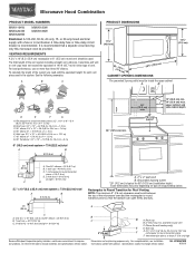
... (15.2 cm = 3 m) E. Exact dimensions may vary depending on type of the system you need, add the equivalent length for 66" (167.6 cm) installation height. For complete details, see Installation our products, we reserve the right to change materials and specifications without notice. Vent extension piece, at least 3" (7.6 cm) high Because Whirlpool Corporation...
... (15.2 cm = 3 m) E. Exact dimensions may vary depending on type of the system you need, add the equivalent length for 66" (167.6 cm) installation height. For complete details, see Installation our products, we reserve the right to change materials and specifications without notice. Vent extension piece, at least 3" (7.6 cm) high Because Whirlpool Corporation...
Warranty Information
Page 1
... in this User Instructions and model number information for other rights that is not installed in accordance with the product, Maytag brand of original purchase date is installed, operated and maintained according to instructions attached to repair or replace appliance light bulbs...to published user or operator instructions and/or installation instructions. 4. Costs associated with electrical or plumbing codes, or use or when it is installed in materials or workmanship and is covered by this warranty. 8. MAYTAG® MICROWAVE-RANGE HOOD COMBINATION LIMITED WARRANTY ...
... in this User Instructions and model number information for other rights that is not installed in accordance with the product, Maytag brand of original purchase date is installed, operated and maintained according to instructions attached to repair or replace appliance light bulbs...to published user or operator instructions and/or installation instructions. 4. Costs associated with electrical or plumbing codes, or use or when it is installed in materials or workmanship and is covered by this warranty. 8. MAYTAG® MICROWAVE-RANGE HOOD COMBINATION LIMITED WARRANTY ...


