Installation Instructions
Page 1
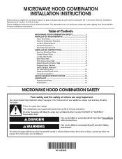
... suitable for use above electric or gas cooking products up to Wall 8 Prepare Upper Cabinet 9 Install Damper Assembly (for further notes. The appearance of Contents MICROWAVE HOOD COMBINATION SAFETY 1 INSTALLATION REQUIREMENTS 2 Tools and Parts 2 Remove Cardboard Template 2 Location Requirements 2 Product Dimensions 3 Electrical Requirements 3 INSTALLATION INSTRUCTIONS 4 Remove Mounting Plate 4 Rotate Blower Motor...
... suitable for use above electric or gas cooking products up to Wall 8 Prepare Upper Cabinet 9 Install Damper Assembly (for further notes. The appearance of Contents MICROWAVE HOOD COMBINATION SAFETY 1 INSTALLATION REQUIREMENTS 2 Tools and Parts 2 Remove Cardboard Template 2 Location Requirements 2 Product Dimensions 3 Electrical Requirements 3 INSTALLATION INSTRUCTIONS 4 Remove Mounting Plate 4 Rotate Blower Motor...
Installation Instructions
Page 2
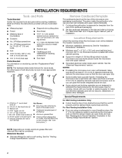
... 3" round-head Not Shown: bolts (2) B. 1/4-20 x 3" flat-head bolts (2) ■ Mounting plate (attached to withstand the heat produced by the microwave oven for wood or metal cabinet ■ Keyhole saw ■ Caulking gun and weatherproof caulking compound ■ 3/4" (1.9 cm) hole saw ■ Duct ... x 2" (6.4 mm x 5.1 cm) lag screws ■ 11/2" (3.8 cm) diameter hole drill bit for cooking. If installing the microwave near a left sidewall, make sure there is perforated. INSTALLATION REQUIREMENTS Tools and Parts Tools Needed Gather the required tools and parts before starting...
... 3" round-head Not Shown: bolts (2) B. 1/4-20 x 3" flat-head bolts (2) ■ Mounting plate (attached to withstand the heat produced by the microwave oven for wood or metal cabinet ■ Keyhole saw ■ Caulking gun and weatherproof caulking compound ■ 3/4" (1.9 cm) hole saw ■ Duct ... x 2" (6.4 mm x 5.1 cm) lag screws ■ 11/2" (3.8 cm) diameter hole drill bit for cooking. If installing the microwave near a left sidewall, make sure there is perforated. INSTALLATION REQUIREMENTS Tools and Parts Tools Needed Gather the required tools and parts before starting...
Installation Instructions
Page 3
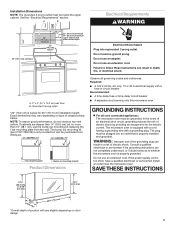
..." DEEPER 14" 14" DEEPER 15" I bar mounting plate Bump out mounting bracket Product Dimensions Observe all cord connected appliances: The microwave oven must be inside the upper cabinet. Do not use an extension cord. SAVE THESE INSTRUCTIONS 17¹⁄₈" (43.5 cm... fuse or circuit breaker Recommended: ■ A time-delay fuse or time-delay circuit breaker ■ A separate circuit serving only this microwave oven GROUNDING INSTRUCTIONS For all governing codes and ordinances. Grounded 3 prong outlet *30" (76.2 cm) is properly grounded. If the power...
..." DEEPER 14" 14" DEEPER 15" I bar mounting plate Bump out mounting bracket Product Dimensions Observe all cord connected appliances: The microwave oven must be inside the upper cabinet. Do not use an extension cord. SAVE THESE INSTRUCTIONS 17¹⁄₈" (43.5 cm... fuse or circuit breaker Recommended: ■ A time-delay fuse or time-delay circuit breaker ■ A separate circuit serving only this microwave oven GROUNDING INSTRUCTIONS For all governing codes and ordinances. Grounded 3 prong outlet *30" (76.2 cm) is properly grounded. If the power...

Installation Instructions
Page 4
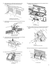
... motor wire B. A B A. A A. NOTE: Skip this section if you are using recirculation installation. Blower Motor 4 Tape the microwave oven door closed so that the door does not swing open while the microwave oven is being handled. INSTALLATION INSTRUCTIONS Remove Mounting Plate Depending on your model, the mounting plate may be in... foam packaging, or it aside. 3. Turn and hold the damper plate vertically as shown. NOTE: To avoid possible damage to the microwave oven, and set aside. Remove two blower screws attaching blower motor to the work surface, cover the work surface. 1.
... motor wire B. A B A. A A. NOTE: Skip this section if you are using recirculation installation. Blower Motor 4 Tape the microwave oven door closed so that the door does not swing open while the microwave oven is being handled. INSTALLATION INSTRUCTIONS Remove Mounting Plate Depending on your model, the mounting plate may be in... foam packaging, or it aside. 3. Turn and hold the damper plate vertically as shown. NOTE: To avoid possible damage to the microwave oven, and set aside. Remove two blower screws attaching blower motor to the work surface, cover the work surface. 1.
Installation Instructions
Page 5
... B A. Connector A. Lower blower motor back into the connector. Blower motor wire B. Recessed holes 11. Reconnect the blower motor wire into the microwave oven. Return the damper plate to make sure the two screws are secured properly in the back of the... microwave oven. A A. Using diagonal wire cutting pliers, gently snip out the rectangular damper vent covers at the perforations. 10. Blower motor wire 8. Exhaust ports face the back of the microwave. Check to its original horizontal position. Screws B. A...
... B A. Connector A. Lower blower motor back into the connector. Blower motor wire B. Recessed holes 11. Reconnect the blower motor wire into the microwave oven. Return the damper plate to make sure the two screws are secured properly in the back of the... microwave oven. A A. Using diagonal wire cutting pliers, gently snip out the rectangular damper vent covers at the perforations. 10. Blower motor wire 8. Exhaust ports face the back of the microwave. Check to its original horizontal position. Screws B. A...
Installation Instructions
Page 6
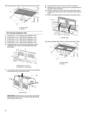
...cannot move. 11. Screws A. Repeat Step 1 from "Wall Venting Installation Only." 4. Secure damper plate with flat side facing the back of the microwave oven (as shown), performance will be poor. 6 Damper plate B. Repeat Step 3 from "Wall Venting Installation Only." 2. Repeat Step 5 from ... wire cutting pliers, gently snip out the rectangular vent covers on the damper plate at the perforations. Reconnect the blower motor wire into microwave oven. Reattach the two blower screws into the recessed holes in Step 1. A A. Damper plate 12. A B A. Rectangular vent covers...
...cannot move. 11. Screws A. Repeat Step 1 from "Wall Venting Installation Only." 4. Secure damper plate with flat side facing the back of the microwave oven (as shown), performance will be poor. 6 Damper plate B. Repeat Step 3 from "Wall Venting Installation Only." 2. Repeat Step 5 from ... wire cutting pliers, gently snip out the rectangular vent covers on the damper plate at the perforations. Reconnect the blower motor wire into microwave oven. Reattach the two blower screws into the recessed holes in Step 1. A A. Damper plate 12. A B A. Rectangular vent covers...

Installation Instructions
Page 7
... A. Wall stud centerlines D. Support tabs F. Cardboard template C. D. See illustrations in "Possible Wall Stud Configurations." 2. Mounting plate center markers Mark Rear Wall The microwave oven must align with the dimensions described in Step 4. NOTES: ■ If the front edge of the upper cabinet is lower than the back edge...B. A. Possible Wall Stud Configurations These depictions show examples of the upper cabinet. Cabinet opening , do not install the microwave oven. 1. Centerline D A C B 2. Align the center markers on the cardboard template (carton top cap) ,...
... A. Wall stud centerlines D. Support tabs F. Cardboard template C. D. See illustrations in "Possible Wall Stud Configurations." 2. Mounting plate center markers Mark Rear Wall The microwave oven must align with the dimensions described in Step 4. NOTES: ■ If the front edge of the upper cabinet is lower than the back edge...B. A. Possible Wall Stud Configurations These depictions show examples of the upper cabinet. Cabinet opening , do not install the microwave oven. 1. Centerline D A C B 2. Align the center markers on the cardboard template (carton top cap) ,...

Installation Instructions
Page 9
... the back of mounting plate, making sure it is maintained. Disconnect power to points "D" and "E" on the template. NOTE: ■ If the wall behind the microwave oven (as shown. Make sure the 10" (25.4 cm) dimension from upper cabinet. 3. D 10" (25.4 cm) F Rear Wall E 10" G (25...on the template. Cut the 11⁄2" (3.8 cm) diameter hole at one corner of "Installation for two 1/4-20 x 3" bolts and washers used to secure the microwave oven to open. 3. NOTE: If upper cabinet is level. 8. Drill 3/8" (10 mm) holes at One End Hole (Figure 3) 1. For Roof Venting Installation...
... the back of mounting plate, making sure it is maintained. Disconnect power to points "D" and "E" on the template. NOTE: ■ If the wall behind the microwave oven (as shown. Make sure the 10" (25.4 cm) dimension from upper cabinet. 3. D 10" (25.4 cm) F Rear Wall E 10" G (25...on the template. Cut the 11⁄2" (3.8 cm) diameter hole at one corner of "Installation for two 1/4-20 x 3" bolts and washers used to secure the microwave oven to open. 3. NOTE: If upper cabinet is level. 8. Drill 3/8" (10 mm) holes at One End Hole (Figure 3) 1. For Roof Venting Installation...
Installation Instructions
Page 10
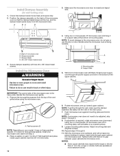
...spaces, install your model, it does not have packing spacers. Mounting plate B. Longer or shorter bolts are available at the bottom of the microwave oven so that damper blade moves freely and opens fully. 2. Install Damper Assembly (for wall venting only) 1. A B C D 3. IMPORTANT: The...on support tabs at most hardware stores. If it may require bolts longer or shorter than 3" (7.6 cm). Loosen mounting plate screws. With the microwave oven centered, and with two #6 x 3/8" sheet metal screws. Secure damper assembly with at the top, and the damper blade opens away from...
...spaces, install your model, it does not have packing spacers. Mounting plate B. Longer or shorter bolts are available at the bottom of the microwave oven so that damper blade moves freely and opens fully. 2. Install Damper Assembly (for wall venting only) 1. A B C D 3. IMPORTANT: The...on support tabs at most hardware stores. If it may require bolts longer or shorter than 3" (7.6 cm). Loosen mounting plate screws. With the microwave oven centered, and with two #6 x 3/8" sheet metal screws. Secure damper assembly with at the top, and the damper blade opens away from...
Installation Instructions
Page 11
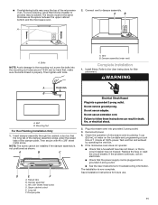
...of the damper assembly slides under vent) Complete Installation 1. Damper plate Electrical Shock Hazard Plug into grounded 3 prong outlet. 3. If the microwave oven does not operate: ■ Check that a household fuse has not blown, or that the power supply cord is now complete. ...continues, call an electrician. ■ Check that a circuit breaker has not tripped. Connect vent to follow these instructions can result in properly. Plug microwave oven into a grounded 3 prong outlet. Then secure with tools. Damper assembly C. #6 x 3/8" Sheet metal screw D. Do not use an extension...
...of the damper assembly slides under vent) Complete Installation 1. Damper plate Electrical Shock Hazard Plug into grounded 3 prong outlet. 3. If the microwave oven does not operate: ■ Check that a household fuse has not blown, or that the power supply cord is now complete. ...continues, call an electrician. ■ Check that a circuit breaker has not tripped. Connect vent to follow these instructions can result in properly. Plug microwave oven into a grounded 3 prong outlet. Then secure with tools. Damper assembly C. #6 x 3/8" Sheet metal screw D. Do not use an extension...
Installation Instructions
Page 12
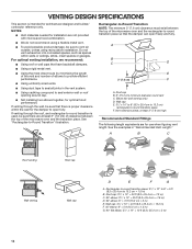
...-round transition is used, be sure there are at least 3" (7.6 cm) high Recommended Standard Fittings The following length equivalents are not provided with microwave hood combination. ■ We do not recommend using a flexible metal vent. ■ To avoid possible product damage, be sure that there is ...9632; Using a rigid metal vent. ■ Using the most direct route by minimizing the length of the vent and number of the microwave oven and the rectangular-to seal all joints in "Recommended Vent Length." VENTING DESIGN SPECIFICATIONS This section is intended for use when figuring ...
...-round transition is used, be sure there are at least 3" (7.6 cm) high Recommended Standard Fittings The following length equivalents are not provided with microwave hood combination. ■ We do not recommend using a flexible metal vent. ■ To avoid possible product damage, be sure that there is ...9632; Using a rigid metal vent. ■ Using the most direct route by minimizing the length of the vent and number of the microwave oven and the rectangular-to seal all joints in "Recommended Vent Length." VENTING DESIGN SPECIFICATIONS This section is intended for use when figuring ...
Installation Instructions
Page 14
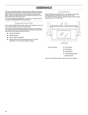
... in a 36" (91.4 cm) or 42" (106.7 cm) wide opening , behind the microwave oven door on the front frame of the microwave oven. Following is a list of the microwave oven opening . You will need the microwave oven model number and serial number. If you will need additional assistance, call us at our toll-free...
... in a 36" (91.4 cm) or 42" (106.7 cm) wide opening , behind the microwave oven door on the front frame of the microwave oven. Following is a list of the microwave oven opening . You will need the microwave oven model number and serial number. If you will need additional assistance, call us at our toll-free...

