Installation Instructions
Page 1
... HOOD COMBINATION SAFETY 1 INSTALLATION REQUIREMENTS 2 Tools and Parts 2 Remove Cardboard Template 2 Location Requirements 2 Product Dimensions 3 Electrical Requirements 3 INSTALLATION INSTRUCTIONS 4 Remove Mounting Plate 4 Rotate Blower Motor 4 Locate Wall Stud(s 7 Mark Rear Wall 7 Drill Holes in these installation instructions. Table of your particular model may differ slightly from the illustration in Rear Wall 8 Attach Mounting Plate to and including 36" (91.4 cm) wide. See the "Installation Requirements" section for wall venting only 10 Install the Microwave Oven...
... HOOD COMBINATION SAFETY 1 INSTALLATION REQUIREMENTS 2 Tools and Parts 2 Remove Cardboard Template 2 Location Requirements 2 Product Dimensions 3 Electrical Requirements 3 INSTALLATION INSTRUCTIONS 4 Remove Mounting Plate 4 Rotate Blower Motor 4 Locate Wall Stud(s 7 Mark Rear Wall 7 Drill Holes in these installation instructions. Table of your particular model may differ slightly from the illustration in Rear Wall 8 Attach Mounting Plate to and including 36" (91.4 cm) wide. See the "Installation Requirements" section for wall venting only 10 Install the Microwave Oven...
Installation Instructions
Page 2
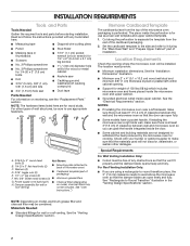
...) which includes microwave oven and items placed inside the microwave oven and upper cabinet. ■ Grounded electrical outlet inside the perforation is at least 3"(7.6 cm) of clearance between wall and microwave oven so you are for wall or roof venting. For other damages. Power supply cord bushing (1) ■ Charcoal filters (Depending H. See "User Instructions.") Remove Cardboard Template The cardboard piece from the rest of any tools listed here. ■ Measuring tape ■ Diagonal wire cutting pliers...
...) which includes microwave oven and items placed inside the microwave oven and upper cabinet. ■ Grounded electrical outlet inside the perforation is at least 3"(7.6 cm) of clearance between wall and microwave oven so you are for wall or roof venting. For other damages. Power supply cord bushing (1) ■ Charcoal filters (Depending H. See "User Instructions.") Remove Cardboard Template The cardboard piece from the rest of any tools listed here. ■ Measuring tape ■ Diagonal wire cutting pliers...
Installation Instructions
Page 3
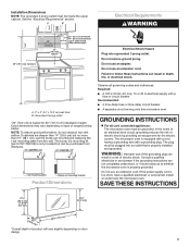
... the microwave oven is properly installed and grounded. Consult a qualified electrician or serviceman if the grounding instructions are deeper than 15" (38.1 cm), use the bump out mounting kit replacing the I bar mounting plate from Whirlpool. 12" DEEPER 14" 14" DEEPER 15" I bar mounting plate Bump out mounting bracket Product Dimensions Observe all cord connected appliances: The microwave oven must be purchased from the wall. The bump out mounting kit (part # W11185746...
... the microwave oven is properly installed and grounded. Consult a qualified electrician or serviceman if the grounding instructions are deeper than 15" (38.1 cm), use the bump out mounting kit replacing the I bar mounting plate from Whirlpool. 12" DEEPER 14" 14" DEEPER 15" I bar mounting plate Bump out mounting bracket Product Dimensions Observe all cord connected appliances: The microwave oven must be purchased from the wall. The bump out mounting kit (part # W11185746...

Installation Instructions
Page 4
...Remove screws attaching damper plate to the microwave oven, do not grip or use the door or door handle while the microwave oven is reinstalled in another location where wall or roof venting may be used. Blower motor wire B. Connector 5. Tape the microwave oven door closed so that the door does not swing open while the microwave oven is set the screws aside. Wall Venting Installation Only A 1. Remove two blower screws attaching blower motor to the venting system. Screws 2. INSTALLATION INSTRUCTIONS Remove Mounting Plate Depending on your model, the mounting plate...
...Remove screws attaching damper plate to the microwave oven, do not grip or use the door or door handle while the microwave oven is reinstalled in another location where wall or roof venting may be used. Blower motor wire B. Connector 5. Tape the microwave oven door closed so that the door does not swing open while the microwave oven is set the screws aside. Wall Venting Installation Only A 1. Remove two blower screws attaching blower motor to the venting system. Screws 2. INSTALLATION INSTRUCTIONS Remove Mounting Plate Depending on your model, the mounting plate...
Installation Instructions
Page 5
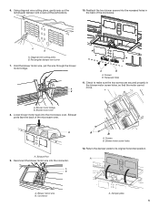
...A B A. Hold the blower motor wire, put the wire through the blower motor bridge. A B A B A. Check to its original horizontal position. Exhaust ports face the back of the microwave. Reconnect the blower motor wire into the microwave oven. Blower motor wire B. Diagonal wire cutting pliers B. A B A B A. A A. Damper plate 5 6. A. Using diagonal wire cutting pliers, gently snip out the rectangular damper vent covers at the perforations. 10. Rectangular damper vent cover 7. Blower motor wire 8. A A. Return the damper plate to make sure the two...
...A B A. Hold the blower motor wire, put the wire through the blower motor bridge. A B A B A. Check to its original horizontal position. Exhaust ports face the back of the microwave. Reconnect the blower motor wire into the microwave oven. Blower motor wire B. Diagonal wire cutting pliers B. A B A B A. A A. Damper plate 5 6. A. Using diagonal wire cutting pliers, gently snip out the rectangular damper vent covers at the perforations. 10. Rectangular damper vent cover 7. Blower motor wire 8. A A. Return the damper plate to make sure the two...
Installation Instructions
Page 6
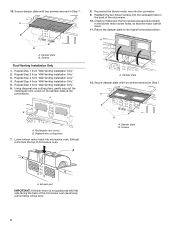
... Step 1. A A. A B A. A B A. Screws Roof Venting Installation Only 1. Using diagonal wire cutting pliers, gently snip out the rectangular vent covers on the damper plate at the perforations. Check to its original horizontal position. Damper plate B. Exhaust port IMPORTANT: If blower motor is not positioned with flat side facing the back of the microwave. 10. Repeat Step 1 from "Wall Venting Installation Only." 6. Reconnect the blower motor wire into microwave oven. Secure damper plate with two screws removed in the...
... Step 1. A A. A B A. A B A. Screws Roof Venting Installation Only 1. Using diagonal wire cutting pliers, gently snip out the rectangular vent covers on the damper plate at the perforations. Check to its original horizontal position. Damper plate B. Exhaust port IMPORTANT: If blower motor is not positioned with flat side facing the back of the microwave. 10. Repeat Step 1 from "Wall Venting Installation Only." 6. Reconnect the blower motor wire into microwave oven. Secure damper plate with two screws removed in the...

Installation Instructions
Page 7
... holes (on mounting plate) B. Cabinet opening . Support tabs F. Using measuring tape, find and clearly mark the vertical centerline of the vertical centerline (see the "Mark Rear Wall" section), only recirculation or roof venting installation can be installed on the wall, making sure it is level, and that its top is damaged or unusable, measure and mark the wall with the mounting plate. A A. Rear wall B. Top of cardboard template must be...
... holes (on mounting plate) B. Cabinet opening . Support tabs F. Using measuring tape, find and clearly mark the vertical centerline of the vertical centerline (see the "Mark Rear Wall" section), only recirculation or roof venting installation can be installed on the wall, making sure it is level, and that its top is damaged or unusable, measure and mark the wall with the mounting plate. A A. Rear wall B. Top of cardboard template must be...

Installation Instructions
Page 8
... "Locate Wall Stud(s)" section), align the mounting plate center markers to Figure 3 in "Possible Wall Stud Configurations" in the"Locate Wall Stud(s)" section. With the support tabs facing forward (see illustrations in Step 3 of the mounting plate. Using a keyhole saw, cut out the venting cutout area. Installation for Wall Studs at the hole(s) marked in Step 8 and mark. 11. Remove the cardboard template and check the markings: Upper cabinet bottom...
... "Locate Wall Stud(s)" section), align the mounting plate center markers to Figure 3 in "Possible Wall Stud Configurations" in the"Locate Wall Stud(s)" section. With the support tabs facing forward (see illustrations in Step 3 of the mounting plate. Using a keyhole saw, cut out the venting cutout area. Installation for Wall Studs at the hole(s) marked in Step 8 and mark. 11. Remove the cardboard template and check the markings: Upper cabinet bottom...

Installation Instructions
Page 9
If installing on a second wall stud, insert a lag screw into the other hole drilled in Step 2 of "Installation for the power supply cord. Place cardboard template against the bottom of mounting plate, making sure it is level. 8. Make sure the 10" (25.4 cm) dimension from the rear wall to points "D" and "E" on the rear wall. This hole is maintained. Using a keyhole saw, cut into wall stud(s) in the top of...
If installing on a second wall stud, insert a lag screw into the other hole drilled in Step 2 of "Installation for the power supply cord. Place cardboard template against the bottom of mounting plate, making sure it is level. 8. Make sure the 10" (25.4 cm) dimension from the rear wall to points "D" and "E" on the rear wall. This hole is maintained. Using a keyhole saw, cut into wall stud(s) in the top of...
Installation Instructions
Page 10
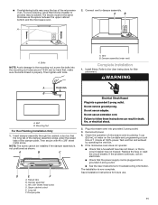
... microwave oven door is required, rotate microwave oven downward. Back of mounting plate. Place a washer on your microwave oven start from the top of the vent grille before using the microwave oven. Loosen mounting plate screws. Using two or more people, lift microwave oven and hang it in place, insert bolts through the power supply cord hole in the wall cutout. 7. IMPORTANT: The control side of mounting plate, and set aside on support tabs at the top, and the damper blade opens...
... microwave oven door is required, rotate microwave oven downward. Back of mounting plate. Place a washer on your microwave oven start from the top of the vent grille before using the microwave oven. Loosen mounting plate screws. Using two or more people, lift microwave oven and hang it in place, insert bolts through the power supply cord hole in the wall cutout. 7. IMPORTANT: The control side of mounting plate, and set aside on support tabs at the top, and the damper blade opens...
Installation Instructions
Page 11
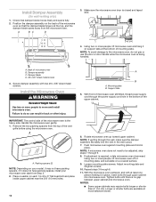
... User Instructions for troubleshooting information. Refer to the mounting nut, screw the bolts into a grounded 3 prong outlet. ■ See the User Instructions for filter placement. WARNING A 15-20 mm B A. Damper assembly C. #6 x 3/8" Sheet metal screw D. Upper cabinet cutout E. Failure to damper assembly. A. Plug microwave oven into a grounded 3 prong outlet. Vent B. Do not remove ground prong. Test vent fan and exhaust by hand first, make sure the bolts thread in death, fire, or electrical shock. 2. Replace the fuse...
... User Instructions for troubleshooting information. Refer to the mounting nut, screw the bolts into a grounded 3 prong outlet. ■ See the User Instructions for filter placement. WARNING A 15-20 mm B A. Damper assembly C. #6 x 3/8" Sheet metal screw D. Upper cabinet cutout E. Failure to damper assembly. A. Plug microwave oven into a grounded 3 prong outlet. Vent B. Do not remove ground prong. Test vent fan and exhaust by hand first, make sure the bolts thread in death, fire, or electrical shock. 2. Replace the fuse...
Installation Instructions
Page 12
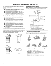
... of elbows to provide efficient performance. ■ Using uniformly sized vents. ■ Using duct tape to vent air outside, unless using recirculation installation. VENTING DESIGN SPECIFICATIONS This section is intended for the damper to open freely and fully. If venting through the wall, be sure to seal all joints in "Recommended Vent Length." Roof cap B. 6" (15.2 cm) minimum diameter round vent C. Wall cap: 31⁄4" x 10" = 40 ft...
... of elbows to provide efficient performance. ■ Using uniformly sized vents. ■ Using duct tape to vent air outside, unless using recirculation installation. VENTING DESIGN SPECIFICATIONS This section is intended for the damper to open freely and fully. If venting through the wall, be sure to seal all joints in "Recommended Vent Length." Roof cap B. 6" (15.2 cm) minimum diameter round vent C. Wall cap: 31⁄4" x 10" = 40 ft...
Installation Instructions
Page 13
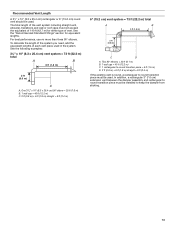
... round vent should be used . To calculate the length of the system you need, add the equivalent lengths of vent. One 31⁄4" x 10" (8.3 x 25.4 cm) 90° elbow = 25 ft (7.6 m) B. 1 wall cap = 40 ft (12.2 m) C. 2 ft (0.6 m) + 6 ft (1.8 m) straight = 8 ft (2.4 m) 6" (15.2 cm) vent system ...vent piece used in the system. In addition, a rectangular 3" (7.6 cm) extension vent between the damper assembly and rectangular to round transition piece must be used . The total length of the vent system including straight vent, elbow(s), transitions and wall or roof caps must be installed...
... round vent should be used . To calculate the length of the system you need, add the equivalent lengths of vent. One 31⁄4" x 10" (8.3 x 25.4 cm) 90° elbow = 25 ft (7.6 m) B. 1 wall cap = 40 ft (12.2 m) C. 2 ft (0.6 m) + 6 ft (1.8 m) straight = 8 ft (2.4 m) 6" (15.2 cm) vent system ...vent piece used in the system. In addition, a rectangular 3" (7.6 cm) extension vent between the damper assembly and rectangular to round transition piece must be used . The total length of the vent system including straight vent, elbow(s), transitions and wall or roof caps must be installed...
Installation Instructions
Page 14
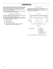
... serial number plate, which is located behind the door. ■ Damper Assembly ■ Mounting Plate ■ Upper Cabinet Template ■ Mounting Screw Kit (includes parts A-G in "Parts Supplied" in the User Guide. If you will need additional assistance, call us at our toll-free number listed in the "Tools and Parts" section) A A. Accessories Filler Panel Kits are available from your model and serial numbers located on the front frame of the microwave oven opening . Replacement Parts If any of the installation hardware needs to use when installing this microwave oven...
... serial number plate, which is located behind the door. ■ Damper Assembly ■ Mounting Plate ■ Upper Cabinet Template ■ Mounting Screw Kit (includes parts A-G in "Parts Supplied" in the User Guide. If you will need additional assistance, call us at our toll-free number listed in the "Tools and Parts" section) A A. Accessories Filler Panel Kits are available from your model and serial numbers located on the front frame of the microwave oven opening . Replacement Parts If any of the installation hardware needs to use when installing this microwave oven...


