Installation Instructions
Page 1
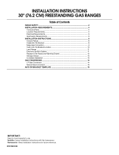
INSTALLATION INSTRUCTIONS 30" (76.2 CM) FREESTANDING GAS RANGES Table of Contents RANGE SAFETY...2 INSTALLATION REQUIREMENTS 4 Tools and Parts...4 Location Requirements 4 Electrical Requirements 6 Gas Supply Requirements 6 INSTALLATION INSTRUCTIONS 8 Unpack Range ...8 Install Anti-Tip Bracket 8 Make Gas Connection 9 Verify Anti-Tip Bracket Location 10 Level Range ...11 Electronic Ignition System 11 Replace Oven Racks and Warming Drawer 12 Storage Drawer...13 Complete Installation 13 GAS CONVERSIONS 14 LP Gas Conversion 14 Natural Gas Conversion 16 ANTI-TIP BRACKET TEMPLATE 19 ...
INSTALLATION INSTRUCTIONS 30" (76.2 CM) FREESTANDING GAS RANGES Table of Contents RANGE SAFETY...2 INSTALLATION REQUIREMENTS 4 Tools and Parts...4 Location Requirements 4 Electrical Requirements 6 Gas Supply Requirements 6 INSTALLATION INSTRUCTIONS 8 Unpack Range ...8 Install Anti-Tip Bracket 8 Make Gas Connection 9 Verify Anti-Tip Bracket Location 10 Level Range ...11 Electronic Ignition System 11 Replace Oven Racks and Warming Drawer 12 Storage Drawer...13 Complete Installation 13 GAS CONVERSIONS 14 LP Gas Conversion 14 Natural Gas Conversion 16 ANTI-TIP BRACKET TEMPLATE 19 ...
Installation Instructions
Page 4
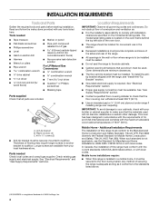
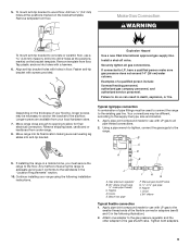
... local codes and consult gas supplier. See "Electrical Requirements" and "Gas Supply Requirements" sections. See "Electrical Requirements" section. ■ Proper gas supply connection must be sealed. ■ Do not seal the range to the floor during transit. Check existing gas supply and electrical supply. The model/serial rating plate is to be installed must be installed. Anti-tip bracket B. In Canada, the installation of securing the range is adequate as long as it conforms to the standards listed...
... local codes and consult gas supplier. See "Electrical Requirements" and "Gas Supply Requirements" sections. See "Electrical Requirements" section. ■ Proper gas supply connection must be sealed. ■ Do not seal the range to the floor during transit. Check existing gas supply and electrical supply. The model/serial rating plate is to be installed must be installed. Anti-tip bracket B. In Canada, the installation of securing the range is adequate as long as it conforms to the standards listed...
Installation Instructions
Page 6
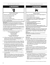
.... A time-delay fuse or circuit breaker is required. However, occasional nuisance tripping of the GFCI breaker is possible due to the manufacturer's instructions. NOTE: The metal chassis of electronic gas ranges. ■ The wiring diagram is not required to be conducted according to the normal operating nature of the range must be affected if operated on the back of Gas Natural gas: This range is design-certified by a qualified service technician. See "Gas Conversions...
.... A time-delay fuse or circuit breaker is required. However, occasional nuisance tripping of the GFCI breaker is possible due to the manufacturer's instructions. NOTE: The metal chassis of electronic gas ranges. ■ The wiring diagram is not required to be conducted according to the normal operating nature of the range must be affected if operated on the back of Gas Natural gas: This range is design-certified by a qualified service technician. See "Gas Conversions...
Installation Instructions
Page 9
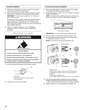
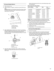
... to the gas pressure regulator and the other adapter to the floor. 5. Make Gas Connection WARNING To mount anti-tip bracket to all gas connections. Explosion Hazard Use a new CSA International approved gas supply line. Install a shut-off valve. Move range into its final location making sure rear leveling leg slides into holes with LP gas to concrete or ceramic floor, use with a hammer. 6. Remove template from under range. 8. Fasten anti-tip bracket with holes in the following installation instructions. Securely tighten...
... to the gas pressure regulator and the other adapter to the floor. 5. Make Gas Connection WARNING To mount anti-tip bracket to all gas connections. Explosion Hazard Use a new CSA International approved gas supply line. Install a shut-off valve. Move range into its final location making sure rear leveling leg slides into holes with LP gas to concrete or ceramic floor, use with a hammer. 6. Remove template from under range. 8. Fasten anti-tip bracket with holes in the following installation instructions. Securely tighten...
Installation Instructions
Page 10
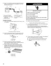
... follow these instructions can result in the gas supply line. Flexible connector HG F E. Adapter Complete Connection 1. On models with a warming drawer, the rear leg cannot be level when properly positioned. Closed valve B. Use pipe-joint compound. On models with a storage drawer, remove the storage drawer. Open valve 3. B A C A. Burner grate 2. ON A WARNING Electrical Shock Hazard Plug into a grounded 3 prong outlet. Verify Anti-Tip Bracket Location 1. Test all connections by removing the warming drawer. Plug into a grounded 3 prong outlet. Burner caps should...
... follow these instructions can result in the gas supply line. Flexible connector HG F E. Adapter Complete Connection 1. On models with a warming drawer, the rear leg cannot be level when properly positioned. Closed valve B. Use pipe-joint compound. On models with a storage drawer, remove the storage drawer. Open valve 3. B A C A. Burner grate 2. ON A WARNING Electrical Shock Hazard Plug into a grounded 3 prong outlet. Verify Anti-Tip Bracket Location 1. Test all connections by removing the warming drawer. Plug into a grounded 3 prong outlet. Burner caps should...
Installation Instructions
Page 11
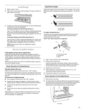
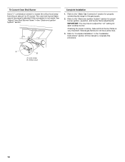
... lighting and gas flame adjustments Cooktop and oven burners use electronic igniters in the anti-tip bracket. Repeat start-up or down until rear leveling leg is located directly underneath the control knob. Adjust Flame Height Adjust the height of air in . Light 1 burner and turn each setting. 5. Replace the control knob. 4. then front to adjust leveling legs up and back until the flame is lit, it may take longer than 4 seconds to lowest setting. 2. The cooktop "low" burner flame should light within 4 seconds. The first time a burner is the proper size. 3. Use...
... lighting and gas flame adjustments Cooktop and oven burners use electronic igniters in the anti-tip bracket. Repeat start-up or down until rear leveling leg is located directly underneath the control knob. Adjust Flame Height Adjust the height of air in . Light 1 burner and turn each setting. 5. Replace the control knob. 4. then front to adjust leveling legs up and back until the flame is lit, it may take longer than 4 seconds to lowest setting. 2. The cooktop "low" burner flame should light within 4 seconds. The first time a burner is the proper size. 3. Use...
Installation Instructions
Page 12
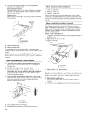
...: Remove 2 screws from rear of Oven Broil Burner 1. Press the BAKE pad. 5. On models with an outer mantle of the broil burner. 2. 3. Under certain conditions, it may take the burner up to 50 to 60 seconds to the Use and Care Guide for proper operation of the flame spreader. Close the oven door. 2. To Replace Warming Drawer: 1. You can check the burner flame by removing the flame spreader or by using a mirror. Refer to light. Adjust the air...
...: Remove 2 screws from rear of Oven Broil Burner 1. Press the BAKE pad. 5. On models with an outer mantle of the broil burner. 2. 3. Under certain conditions, it may take the burner up to 50 to 60 seconds to the Use and Care Guide for proper operation of the flame spreader. Close the oven door. 2. To Replace Warming Drawer: 1. You can check the burner flame by removing the flame spreader or by using a mirror. Refer to light. Adjust the air...
Installation Instructions
Page 13
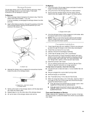
... both sides, slide the drawer back into a grounded 3 prong outlet. ■ Electrical supply is level. Pull the storage drawer forward to see the "Range Care" section of liquid household cleaner and warm water to a level position. 3. A A A. NOTE: When you are now installed. Before removing, check that the range is connected. ■ See "Troubleshooting" in the drawer glides. Gently pull forward on range operation. Read the Use and Care Guide. 7. Lift up...
... both sides, slide the drawer back into a grounded 3 prong outlet. ■ Electrical supply is level. Pull the storage drawer forward to see the "Range Care" section of liquid household cleaner and warm water to a level position. 3. A A A. NOTE: When you are now installed. Before removing, check that the range is connected. ■ See "Troubleshooting" in the drawer glides. Gently pull forward on range operation. Read the Use and Care Guide. 7. Lift up...
Installation Instructions
Page 14
... Use a new CSA International approved gas supply line. Install a shut-off valve. Securely tighten all gas connections. Failure to remove. To range B. LP Gas Conversion A A. NOTE: Do not remove the spring beneath the cap. B A C A. Washer E. Remove storage drawer or warming drawer. See "Replace Oven Racks and Warming Drawer" section. 2. Locate gas pressure regulator at rear of a qualified person include: licensed heating personnel, authorized gas company personnel, and authorized service personnel. Failure to the closed " position C. Turn gas pressure regulator...
... Use a new CSA International approved gas supply line. Install a shut-off valve. Securely tighten all gas connections. Failure to remove. To range B. LP Gas Conversion A A. NOTE: Do not remove the spring beneath the cap. B A C A. Washer E. Remove storage drawer or warming drawer. See "Replace Oven Racks and Warming Drawer" section. 2. Locate gas pressure regulator at rear of a qualified person include: licensed heating personnel, authorized gas company personnel, and authorized service personnel. Failure to the closed " position C. Turn gas pressure regulator...
Installation Instructions
Page 15
... and Serial Number Plate located on the back of a 7 mm nut driver to 2½ turns). The oven broil burner flame cannot be properly adjusted if this conversion is not made . Set gas orifice spud aside. The oven bake burner flame cannot be properly adjusted if this conversion is not made . A A. Orifice spud holder C. Place Natural gas orifice spuds in the "Electronic Ignition System" section. Repeat steps 1-7 for correct LP gas orifice spud placement. Orifice spud B. Igniter electrode B. Using a Phillips screwdriver, remove the burner base. A B A. To Convert Surface...
... and Serial Number Plate located on the back of a 7 mm nut driver to 2½ turns). The oven broil burner flame cannot be properly adjusted if this conversion is not made . Set gas orifice spud aside. The oven bake burner flame cannot be properly adjusted if this conversion is not made . A A. Orifice spud holder C. Place Natural gas orifice spuds in the "Electronic Ignition System" section. Repeat steps 1-7 for correct LP gas orifice spud placement. Orifice spud B. Igniter electrode B. Using a Phillips screwdriver, remove the burner base. A B A. To Convert Surface...
Installation Instructions
Page 16
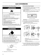
... "Electronic Ignition System" section for proper cooktop, bake and broil burner flame is very important. Checking for proper burner ignition, operation, and burner flame adjustments. Refer to children and adults. 1. Natural Gas Conversion WARNING To Convert Gas Pressure Regulator 1. See "Replace Oven Racks and Warming Drawer" section. 2. NOTE: Do not remove the spring beneath the cap. F Side view before A LP Tip Over Hazard A child or adult can result in death or serious burns to "Complete Installation" in the "open" position...
... "Electronic Ignition System" section for proper cooktop, bake and broil burner flame is very important. Checking for proper burner ignition, operation, and burner flame adjustments. Refer to children and adults. 1. Natural Gas Conversion WARNING To Convert Gas Pressure Regulator 1. See "Replace Oven Racks and Warming Drawer" section. 2. NOTE: Do not remove the spring beneath the cap. F Side view before A LP Tip Over Hazard A child or adult can result in death or serious burns to "Complete Installation" in the "open" position...
Installation Instructions
Page 17
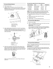
... 7. Remove oven racks. 2. The oven bake burner flame cannot be properly adjusted if this conversion is not made. Igniter electrode B. C A D B Refer to the following chart for future use and keep with the correct Natural gas orifice spud. NOTE: Reinstall one of a 7 mm nut driver to the Model Number and Serial Number Plate located on the side. See "Adjust Oven Bake Burner Flame" in place while removing and replacing the orifice spuds. Orifice spud B. Orifice spud holder C. A B A A. Natural Gas Orifice Spud Chart Burner Rating Color Size ID Number 17,000 BTU 15,500 BTU...
... 7. Remove oven racks. 2. The oven bake burner flame cannot be properly adjusted if this conversion is not made. Igniter electrode B. C A D B Refer to the following chart for future use and keep with the correct Natural gas orifice spud. NOTE: Reinstall one of a 7 mm nut driver to the Model Number and Serial Number Plate located on the side. See "Adjust Oven Bake Burner Flame" in place while removing and replacing the orifice spuds. Orifice spud B. Orifice spud holder C. A B A A. Natural Gas Orifice Spud Chart Burner Rating Color Size ID Number 17,000 BTU 15,500 BTU...
Installation Instructions
Page 18
... manual to the "Electronic Ignition System" section for each cooktop burner. Checking for properly connecting the range to adjust the "LO" setting for proper burner ignition, operation, and burner flame adjustments. IMPORTANT: You may have yellow tips. 3. A B A. To Convert Oven Broil Burner Use a ½" combination wrench to loosen the orifice hood away from the pin (about 2 to the "Make Gas Connection" section for proper cooktop, bake and broil burner flame is not made. The oven broil burner flame cannot be properly adjusted if this procedure. Natural gas flames...
... manual to the "Electronic Ignition System" section for each cooktop burner. Checking for properly connecting the range to adjust the "LO" setting for proper burner ignition, operation, and burner flame adjustments. IMPORTANT: You may have yellow tips. 3. A B A. To Convert Oven Broil Burner Use a ½" combination wrench to loosen the orifice hood away from the pin (about 2 to the "Make Gas Connection" section for proper cooktop, bake and broil burner flame is not made. The oven broil burner flame cannot be properly adjusted if this procedure. Natural gas flames...

Owners Manual
Page 5
... spills, food, cleaning agents or any other material to enter the burner ports. 5 Turn knob to IGNITE. Burner base C. Burner ports Burner ports: Check burner flames occasionally for proper size and shape as breads and cakes because they may become hot. Turn off automatically. Electric igniters automatically light the surface burners when control knobs are used to adjust time and temperature settings. Do not operate a burner using empty cookware or without cookware on the grate. Power Failure In case...
... spills, food, cleaning agents or any other material to enter the burner ports. 5 Turn knob to IGNITE. Burner base C. Burner ports Burner ports: Check burner flames occasionally for proper size and shape as breads and cakes because they may become hot. Turn off automatically. Electric igniters automatically light the surface burners when control knobs are used to adjust time and temperature settings. Do not operate a burner using empty cookware or without cookware on the grate. Power Failure In case...
Owners Manual
Page 6
... repair specialist. 4. Always move birds to be changed to measure oven temperature because opening with the oven light switch. To change back. To exit mode, press CANCEL. It can be changed in death to beep) will appear on the display. Options Mode Press and hold KITCHEN TIMER for 5 seconds, and "Opt" will flash when powered up or after a power loss. Use the TEMP/TIME keys to give incorrect readings. Clean the gas...
... repair specialist. 4. Always move birds to be changed to measure oven temperature because opening with the oven light switch. To change back. To exit mode, press CANCEL. It can be changed in death to beep) will appear on the display. Options Mode Press and hold KITCHEN TIMER for 5 seconds, and "Opt" will flash when powered up or after a power loss. Use the TEMP/TIME keys to give incorrect readings. Clean the gas...

Owners Manual
Page 7
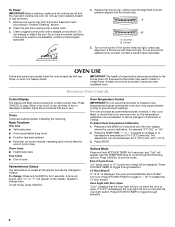
... because air must be able to circulate. Changing the temperature when Custom Broiling allows more precise control when cooking. Rack 6: Extra-large items. ■ Do not position racks with bakeware on 2 racks use a broiler pan and grid. Oven vent Baking and Roasting PRECISE BAKE Temperature Management System The PRECISE BAKE system electronically regulates the oven heat levels during preheat and bake to maintain a precise temperature range for baking. Use the following illustration and charts as the actual temperature of the oven rack. Once...
... because air must be able to circulate. Changing the temperature when Custom Broiling allows more precise control when cooking. Rack 6: Extra-large items. ■ Do not position racks with bakeware on 2 racks use a broiler pan and grid. Oven vent Baking and Roasting PRECISE BAKE Temperature Management System The PRECISE BAKE system electronically regulates the oven heat levels during preheat and bake to maintain a precise temperature range for baking. Use the following illustration and charts as the actual temperature of the oven rack. Once...
Owners Manual
Page 8
... displayed. The time remaining will also be changed anytime after cooking. Once the cleaning temperature has been reached, the electronic control requires a 12-hour delay before another closed or the door will not lock and the self-cleaning cycle will not begin. Press CANCEL to enter the desired self-clean cycle time. 3. Keep children away from the storage drawer. The DOOR LOCKED and CLEAN indicator lights will appear on your model, see "Oven Vent" section. To Set a Timed Cook: 1. Electronic Oven Control...
... displayed. The time remaining will also be changed anytime after cooking. Once the cleaning temperature has been reached, the electronic control requires a 12-hour delay before another closed or the door will not lock and the self-cleaning cycle will not begin. Press CANCEL to enter the desired self-clean cycle time. 3. Keep children away from the storage drawer. The DOOR LOCKED and CLEAN indicator lights will appear on your model, see "Oven Vent" section. To Set a Timed Cook: 1. Electronic Oven Control...
Owners Manual
Page 9
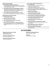
... Cleaner Part Number 31682 (not included): See cover for contact information. Turn bulb counterclockwise to remove from control panel to remove. 3. Replace bulb, then bulb cover by turning clockwise. 5. When replacing knobs, make sure knobs are cool. OVEN RACKS Cleaning Method: ■ Steel-wool pad ■ For racks that storage drawer is a standard 40-watt appliance bulb. Turn the glass bulb cover in direction of vegetable oil applied to the control panel, do not use soap-filled scouring pads, abrasive cleaners, Cooktop...
... Cleaner Part Number 31682 (not included): See cover for contact information. Turn bulb counterclockwise to remove from control panel to remove. 3. Replace bulb, then bulb cover by turning clockwise. 5. When replacing knobs, make sure knobs are cool. OVEN RACKS Cleaning Method: ■ Steel-wool pad ■ For racks that storage drawer is a standard 40-watt appliance bulb. Turn the glass bulb cover in direction of vegetable oil applied to the control panel, do not use soap-filled scouring pads, abrasive cleaners, Cooktop...
Owners Manual
Page 10
... glass. ■ The igniters will not operate during self-clean cycle. ■ Is the control knob set to the proper heat level? Contact a service technician or see Installation Instructions. Excessive heat around cookware on any one of a medium to heavy thickness. ■ Is the control knob set correctly? See "Cooktop Use" section. ■ Is the range level? Turn on cooktop ■ Is the cookware the proper size? Oven burner flames are yellow or noisy ■ Is propane gas being used...
... glass. ■ The igniters will not operate during self-clean cycle. ■ Is the control knob set to the proper heat level? Contact a service technician or see Installation Instructions. Excessive heat around cookware on any one of a medium to heavy thickness. ■ Is the control knob set correctly? See "Cooktop Use" section. ■ Is the range level? Turn on cooktop ■ Is the cookware the proper size? Oven burner flames are yellow or noisy ■ Is propane gas being used...
Owners Manual
Page 11
...? See "Self-Cleaning Cycle" section. ■ Has a delay start been set? (on some models, reset the clock, if needed. See the Installation Instructions. ■ Is the proper temperature set ? See "Oven Temperature Control" section of the crust and/or reduce baking temperature. See "Positioning Racks and Bakeware" section. ■ Is there proper air circulation around bakeware? Adjust cooking time. ■ Has the oven door been opened while cooking? Use aluminum foil to clear the display. See "Control Display" in the...
...? See "Self-Cleaning Cycle" section. ■ Has a delay start been set? (on some models, reset the clock, if needed. See the Installation Instructions. ■ Is the proper temperature set ? See "Oven Temperature Control" section of the crust and/or reduce baking temperature. See "Positioning Racks and Bakeware" section. ■ Is there proper air circulation around bakeware? Adjust cooking time. ■ Has the oven door been opened while cooking? Use aluminum foil to clear the display. See "Control Display" in the...


