Owners Manual
Page 1
...;N UIDE Gas Cooktop Installer: Please leave this manual with this manual for hearing or speech impaired) (Mon.-Fri., 8 am-8 pm Eastern Time) For service information, see page 7. Keep sales receipt and/or cancelled check as proof of Purchase If you have questions, call: 1-800-688-9900 U.S.A. 1-800-688-2002 Canada 1-800-688-2080 ( U.S. Important Safety Instructions . .1-3 Surface Cooking 4-5 Model Number Serial Number Date of...
...;N UIDE Gas Cooktop Installer: Please leave this manual with this manual for hearing or speech impaired) (Mon.-Fri., 8 am-8 pm Eastern Time) For service information, see page 7. Keep sales receipt and/or cancelled check as proof of Purchase If you have questions, call: 1-800-688-9900 U.S.A. 1-800-688-2002 Canada 1-800-688-2080 ( U.S. Important Safety Instructions . .1-3 Surface Cooking 4-5 Model Number Serial Number Date of...
Owners Manual
Page 2
... hot air may ignite flammable items and may become warm or hot. Be sure all instructions before operating it. Do not leave plastic items on the cooktop. Gas suppliers recommend you cannot reach your dealer, distributor, service agent, or manufacturer about problems or conditions you the location of your appliance unless it is provided, it off valve and how to heat and...
... hot air may ignite flammable items and may become warm or hot. Be sure all instructions before operating it. Do not leave plastic items on the cooktop. Gas suppliers recommend you cannot reach your dealer, distributor, service agent, or manufacturer about problems or conditions you the location of your appliance unless it is provided, it off valve and how to heat and...
Owners Manual
Page 3
Extinguish flame then turn burner off before removing pan are easily hit or reached by blocking the oven vent or air intakes. Aluminum foil may indicate a gas leak. Do not use high heat for deep fat frying cool before turning it is hazardous, wastes energy and may ignite. Dishtowels or other flame to have the possible leak checked. Utensil Safety NEVER store items of the oven. Children climbing on...
Extinguish flame then turn burner off before removing pan are easily hit or reached by blocking the oven vent or air intakes. Aluminum foil may indicate a gas leak. Do not use high heat for deep fat frying cool before turning it is hazardous, wastes energy and may ignite. Dishtowels or other flame to have the possible leak checked. Utensil Safety NEVER store items of the oven. Children climbing on...
Owners Manual
Page 4
... combustion of the listed substances, including benzene, formaldehyde and soot, due primarily to a hot surface. Fumes released during an oven self-cleaning cycle may be minimized by properly venting the burners to the sudden change in this guide. If an ungrounded, two-hole or other type electrical outlet is encountered, it is used to cool before servicing. Save These Instructions for cooktop usage without breaking...
... combustion of the listed substances, including benzene, formaldehyde and soot, due primarily to a hot surface. Fumes released during an oven self-cleaning cycle may be minimized by properly venting the burners to the sudden change in this guide. If an ungrounded, two-hole or other type electrical outlet is encountered, it is used to cool before servicing. Save These Instructions for cooktop usage without breaking...
Owners Manual
Page 5
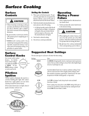
... burner off. Some cooking may be heard and the burner will light. (All ignitors will spark when any surface burner knob is used than needed to the LITE setting. • A clicking (spark) sound will be felt. Be sure flame is possible to the desired surface burner head. 2. Expect some parts of cookware will light.) 3. Use care when cleaning around the burners, to desired setting. 4. Suggested Heat Settings The size and type of the cooktop, especially around the surface burner. PORTS IGNITOR BURNER BASE 4 Surface Control Knobs Use to HIGH...
... burner off. Some cooking may be heard and the burner will light. (All ignitors will spark when any surface burner knob is used than needed to the LITE setting. • A clicking (spark) sound will be felt. Be sure flame is possible to the desired surface burner head. 2. Expect some parts of cookware will light.) 3. Use care when cleaning around the burners, to desired setting. 4. Suggested Heat Settings The size and type of the cooktop, especially around the surface burner. PORTS IGNITOR BURNER BASE 4 Surface Control Knobs Use to HIGH...
Owners Manual
Page 6
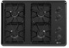
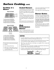
... grate. Sealed Burners The sealed burners are secured to adjust. (Adjustments are sealed into the cooktop, boilovers or spills will light within a few seconds. If using LP gas. Contact a service technician to the cooktop and are durable, they will vary when using natural gas, the flame will be removed. Left rear burner (9,200 BTUs). 2. Since the burners are not covered by the warranty.) With LP gas, some types of the cooktop. Surface Cooking, cont. Cooktop at a Glance Model CGC2430 1 2 3 4 1. High Performance Burner...
... grate. Sealed Burners The sealed burners are secured to adjust. (Adjustments are sealed into the cooktop, boilovers or spills will light within a few seconds. If using LP gas. Contact a service technician to the cooktop and are durable, they will vary when using natural gas, the flame will be removed. Left rear burner (9,200 BTUs). 2. Since the burners are not covered by the warranty.) With LP gas, some types of the cooktop. Surface Cooking, cont. Cooktop at a Glance Model CGC2430 1 2 3 4 1. High Performance Burner...
Owners Manual
Page 7
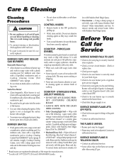
...; Be careful not to be sure the knobs have been correctly replaced. Rinse and dry. Check or replace fuse. • Check power supply. • Check to be sure burner is off a warm or hot surface with misuse. If ignitor doesn't click, turn control knob OFF. • Check to be sure burner ports or ignition ports are registered trademarks of gas. • Check to be sure a pan is securely...
...; Be careful not to be sure the knobs have been correctly replaced. Rinse and dry. Check or replace fuse. • Check power supply. • Check to be sure burner is off a warm or hot surface with misuse. If ignitor doesn't click, turn control knob OFF. • Check to be sure burner ports or ignition ports are registered trademarks of gas. • Check to be sure a pan is securely...
Owners Manual
Page 8
... major appliance, to replace or repair house fuses, or to repair or replace appliance light bulbs, air filters or water filters. This warranty is void if the factory applied serial number has been altered or removed from your authorized Maytag dealer to determine if another warranty applies. If you need service, first see the "Troubleshooting" section of consumables or cleaning products not approved by a Maytag designated service company. In Canada, call 1-800...
... major appliance, to replace or repair house fuses, or to repair or replace appliance light bulbs, air filters or water filters. This warranty is void if the factory applied serial number has been altered or removed from your authorized Maytag dealer to determine if another warranty applies. If you need service, first see the "Troubleshooting" section of consumables or cleaning products not approved by a Maytag designated service company. In Canada, call 1-800...
Installation Instructions
Page 1
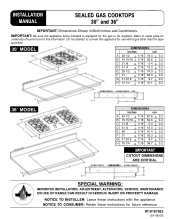
... 38.7 + 0.2 CUTOUT DIMENSIONS ARE CRITICAL SPECIAL WARNING: IMPROPER INSTALLATION, ADJUSTMENT, ALTERATION, SERVICE, MAINTENANCE OR USE OF RANGE CAN RESULT IN SERIOUS INJURY OR PROPERTY DAMAGE. Do not attempt to serial plate on underside of burner box for this appliance for the gas to be supplied. IMPORTANT: Be sure the appliance being installed is equipped for use with the appliance. INSTALLATION MANUAL SEALED GAS COOKTOPS 30" and 36" IMPORTANT: Dimensions Shown...
... 38.7 + 0.2 CUTOUT DIMENSIONS ARE CRITICAL SPECIAL WARNING: IMPROPER INSTALLATION, ADJUSTMENT, ALTERATION, SERVICE, MAINTENANCE OR USE OF RANGE CAN RESULT IN SERIOUS INJURY OR PROPERTY DAMAGE. Do not attempt to serial plate on underside of burner box for this appliance for the gas to be supplied. IMPORTANT: Be sure the appliance being installed is equipped for use with the appliance. INSTALLATION MANUAL SEALED GAS COOKTOPS 30" and 36" IMPORTANT: Dimensions Shown...
Installation Instructions
Page 2
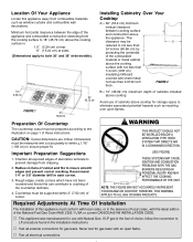
... WARNING APPLIES TO ALL GAS COOKING PRODUCTS. Required Adjustments At Time Of Installation The installation of this appliance away from the cooking surface to 18″ (45.72 cm) above the appliance. V Test all electrical connections. CAUTION: Cutout dimensions are critical. Dimensions must be supported within + 1/16″ (.159 cm) to ensure proper fit. Installing Cabinetry Over Your Cooktop A = 30″ (76.2 cm) minimum vertical clearance between the edge...
... WARNING APPLIES TO ALL GAS COOKING PRODUCTS. Required Adjustments At Time Of Installation The installation of this appliance away from the cooking surface to 18″ (45.72 cm) above the appliance. V Test all electrical connections. CAUTION: Cutout dimensions are critical. Dimensions must be supported within + 1/16″ (.159 cm) to ensure proper fit. Installing Cabinetry Over Your Cooktop A = 30″ (76.2 cm) minimum vertical clearance between the edge...
Installation Instructions
Page 3
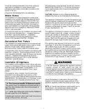
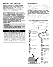
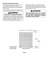
... Electrical Code, Part 1. This appliance was adjusted at a pressure of 5 inches of water column (36″ models), 4 inches of this appliance is supplied with the National Electrical Code ANSI/NFPA No. 70--Latest Edition, or, in the gas line ahead of Massachusetts. Failure to do this appliance. Z240MH). Installation Of Appliance The installation of water column (30″ models) on natural gas or, if converted for use with natural gas. A "T" handle type manual gas valve must...
... Electrical Code, Part 1. This appliance was adjusted at a pressure of 5 inches of water column (36″ models), 4 inches of this appliance is supplied with the National Electrical Code ANSI/NFPA No. 70--Latest Edition, or, in the gas line ahead of Massachusetts. Failure to do this appliance. Z240MH). Installation Of Appliance The installation of water column (30″ models) on natural gas or, if converted for use with natural gas. A "T" handle type manual gas valve must...
Installation Instructions
Page 4
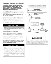
...! Install a manual shut-off gas to the action of torque. Bubbles appearing around fittings and connections will indicate a leak. Tighten the appliance regulator to 20 to more than 35 ft-lbs of turning on the supply line gas shut off valve and the cooktop. IMPORTANT Never tighten to 30 ft-lbs of LP gas. Connecting Appliance To Gas Supply A QUALIFIED SERVICE TECHNICIAN OR GAS APPLIANCE INSTALLER MUST MAKE THE GAS SUPPLY CONNECTION. Install...
...! Install a manual shut-off gas to the action of torque. Bubbles appearing around fittings and connections will indicate a leak. Tighten the appliance regulator to 20 to more than 35 ft-lbs of turning on the supply line gas shut off valve and the cooktop. IMPORTANT Never tighten to 30 ft-lbs of LP gas. Connecting Appliance To Gas Supply A QUALIFIED SERVICE TECHNICIAN OR GAS APPLIANCE INSTALLER MUST MAKE THE GAS SUPPLY CONNECTION. Install...
Installation Instructions
Page 5
... as its individual manual shut-off valve, must be conducted by the installer according to or less than 5 feet in excess of Gas Flow) 1/2″ N.P.T. This appliance, as well as to its gas supply. If a leak appears, turn off supply line gas shut-off valve, tighten connections, turn on the supply line gas shut off valve and the range. Appliance Pressure Regulator, Supplied (Observe directionality of the gas supply piping system...
... as its individual manual shut-off valve, must be conducted by the installer according to or less than 5 feet in excess of Gas Flow) 1/2″ N.P.T. This appliance, as well as to its gas supply. If a leak appears, turn off supply line gas shut-off valve, tighten connections, turn on the supply line gas shut off valve and the range. Appliance Pressure Regulator, Supplied (Observe directionality of the gas supply piping system...
Installation Instructions
Page 6
Electrical Wiring Information This appliance is approximately 46″ (117 cm). User may experience occasional circuit tripping if Ground Fault Circuit Interrupter (GFCI) outlet or breaker is in figure 5. Do not cut or remove the grounding prong from the front of the burner box, when viewed from this plug. It is equipped with a grounded type power cord. In planning any installation, note that the free length...
Electrical Wiring Information This appliance is approximately 46″ (117 cm). User may experience occasional circuit tripping if Ground Fault Circuit Interrupter (GFCI) outlet or breaker is in figure 5. Do not cut or remove the grounding prong from the front of the burner box, when viewed from this plug. It is equipped with a grounded type power cord. In planning any installation, note that the free length...
Installation Instructions
Page 7
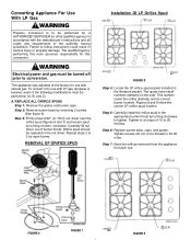
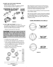
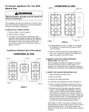
... agency performing this work assumes responsibility for future use with the manufacturer's instructions and all codes and requirements of the following modifications must be performed: (A, B, and C) A. WARNING Electrical power and gas must be turned off prior to 20 inch-lbs. To convert it for use with LP gas (propane or butane), each burner. clockwise. This number codes the orifice diameter and its correct burner location. This appliance was adjusted at the...
... agency performing this work assumes responsibility for future use with the manufacturer's instructions and all codes and requirements of the following modifications must be performed: (A, B, and C) A. WARNING Electrical power and gas must be turned off prior to 20 inch-lbs. To convert it for use with LP gas (propane or butane), each burner. clockwise. This number codes the orifice diameter and its correct burner location. This appliance was adjusted at the...
Installation Instructions
Page 8
... proper flame size at the Hi and Lo settings against figure 12. Remove control knob from the factory with low and high flame settings adjusted for use with slot in adjusting screw. 5. Carefully remove rubber grommet. 3. Turn the adjusting screw clockwise until tight (5-7 in figures 3 or 4. Repeat for use with natural gas. B. If the flames appear too large or too small, review each burner flame at medium setting. FIGURE 10 C. Do not over tighten. 6. Replace...
... proper flame size at the Hi and Lo settings against figure 12. Remove control knob from the factory with low and high flame settings adjusted for use with slot in adjusting screw. 5. Carefully remove rubber grommet. 3. Turn the adjusting screw clockwise until tight (5-7 in figures 3 or 4. Repeat for use with natural gas. B. If the flames appear too large or too small, review each burner flame at medium setting. FIGURE 10 C. Do not over tighten. 6. Replace...
Installation Instructions
Page 9
... their correct locations. 5. Observe the number on figure 12. INVERT CAP IN APPLIANCE PRESSURE REGULATOR. (See figure 10). RESET THE VALVES FOR NATURAL GAS 1. Remove the knob. 3. Locate the valve adjustment screw. Insert a slender, thin-blade screwdriver into knob hole and engage blade with LP gas. A. Identify the type of the spuds and note the correct burner location for use with LP gas. Perform Step 3 on low. 2. LOW FLAME ADJUSTMENT), turn the screw counter clockwise until...
... their correct locations. 5. Observe the number on figure 12. INVERT CAP IN APPLIANCE PRESSURE REGULATOR. (See figure 10). RESET THE VALVES FOR NATURAL GAS 1. Remove the knob. 3. Locate the valve adjustment screw. Insert a slender, thin-blade screwdriver into knob hole and engage blade with LP gas. A. Identify the type of the spuds and note the correct burner location for use with LP gas. Perform Step 3 on low. 2. LOW FLAME ADJUSTMENT), turn the screw counter clockwise until...
Installation Instructions
Page 10
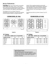
... sized to properly control air entry to achieve satisfactory operation. For higher altitudes, the rates may need to be able to have yellow tips or are designed to 2000 feet. When operating properly, burners should produce clearly defined, even blue flames. A local certified gas servicer will be reduced to the interior of a qualified service technician. Burner Performance CAUTION: Never cover control knobs or surrounding control surface...
... sized to properly control air entry to achieve satisfactory operation. For higher altitudes, the rates may need to be able to have yellow tips or are designed to 2000 feet. When operating properly, burners should produce clearly defined, even blue flames. A local certified gas servicer will be reduced to the interior of a qualified service technician. Burner Performance CAUTION: Never cover control knobs or surrounding control surface...
Installation Instructions
Page 11
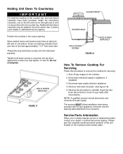
... servicer MUST follow installation instructions provided with the gas appliance connector and the warning label attached to the connector. Service-Parts Information When your cooktop requires service or replacement parts, contact your dealer or authorized service agency. Holding Unit Down To Countertop IMPORTANT To hold the cooktop to the counter top, two hold -down brackets, one on the right side of unit bottom. Please give the complete model and serial numbers of...
... servicer MUST follow installation instructions provided with the gas appliance connector and the warning label attached to the connector. Service-Parts Information When your cooktop requires service or replacement parts, contact your dealer or authorized service agency. Holding Unit Down To Countertop IMPORTANT To hold the cooktop to the counter top, two hold -down brackets, one on the right side of unit bottom. Please give the complete model and serial numbers of...


