Installation Guide
Page 1
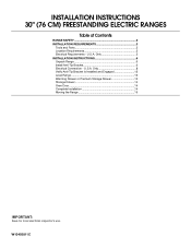
Only 5 INSTALLATION INSTRUCTIONS 6 Unpack Range 6 Install Anti-Tip Bracket 6 Electrical Connection - U.S.A. Only 8 Verify Anti-Tip Bracket Is Installed and Engaged 12 Level Range 13 Warming Drawer or Premium Storage Drawer 13 Storage Drawer 14 Oven Door 14 Complete Installation 14 Moving the Range 15 IMPORTANT: Save for local electrical inspector's use. U.S.A. W10403811C INSTALLATION INSTRUCTIONS 30" (76 CM) FREESTANDING ELECTRIC RANGES Table of Contents RANGE SAFETY 2 INSTALLATION REQUIREMENTS 3 Tools and Parts 3 Location Requirements 3 Electrical Requirements -
Only 5 INSTALLATION INSTRUCTIONS 6 Unpack Range 6 Install Anti-Tip Bracket 6 Electrical Connection - U.S.A. Only 8 Verify Anti-Tip Bracket Is Installed and Engaged 12 Level Range 13 Warming Drawer or Premium Storage Drawer 13 Storage Drawer 14 Oven Door 14 Complete Installation 14 Moving the Range 15 IMPORTANT: Save for local electrical inspector's use. U.S.A. W10403811C INSTALLATION INSTRUCTIONS 30" (76 CM) FREESTANDING ELECTRIC RANGES Table of Contents RANGE SAFETY 2 INSTALLATION REQUIREMENTS 3 Tools and Parts 3 Location Requirements 3 Electrical Requirements -
Installation Guide
Page 2
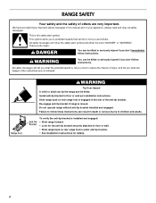
...appliance. All safety messages will tell you what can be killed. All safety messages will follow instructions. Re-engage anti-tip bracket if range is the safety alert symbol. We have provided many important safety messages in the slot of the anti-tip bracket. WARNING You can ... is moved. Anti-Tip Bracket To verify the anti-tip bracket is under anti-tip bracket. • See installation instructions for details. 2 RANGE SAFETY Your safety and the safety of others . This symbol alerts you to potential hazards that can kill or hurt you don't follow these instructions...
...appliance. All safety messages will tell you what can be killed. All safety messages will follow instructions. Re-engage anti-tip bracket if range is the safety alert symbol. We have provided many important safety messages in the slot of the anti-tip bracket. WARNING You can ... is moved. Anti-Tip Bracket To verify the anti-tip bracket is under anti-tip bracket. • See installation instructions for details. 2 RANGE SAFETY Your safety and the safety of others . This symbol alerts you to potential hazards that can kill or hurt you don't follow these instructions...
Installation Guide
Page 3
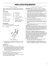
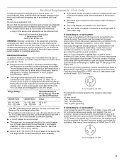
...■ It is required. This oven has been designed in accordance with the requirements of UL and CSA International and complies with the range, see "Install Anti-Tip Bracket" section. ■ Grounded electrical supply is the installer's responsibility to floor. Additional Installation Requirements The ...is marked for Mobile Home Construction and Safety, Title 24, HUD Part 280). Mobile home installations require: ■ When this range is recommended that all electrical connections be made by reaching over heated surface units, cabinet storage space located above the surface units ...
...■ It is required. This oven has been designed in accordance with the requirements of UL and CSA International and complies with the range, see "Install Anti-Tip Bracket" section. ■ Grounded electrical supply is the installer's responsibility to floor. Additional Installation Requirements The ...is marked for Mobile Home Construction and Safety, Title 24, HUD Part 280). Mobile home installations require: ■ When this range is recommended that all electrical connections be made by reaching over heated surface units, cabinet storage space located above the surface units ...
Installation Guide
Page 4
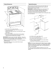
...height (max.) with not less than ¹⁄₄" (0.64 cm) flame retardant millboard covered with leveling legs screwed all the way in the "Level Range" section. upper cabinet depth B. 30" (76.2 cm) min. Outlet - 8" (20.3 cm) to combustible walls with zero clearance. A C B ...cm) depth - For minimum clearance to front of the door or either cabinet, 5¹⁄₂" (14.0 cm) max. A freestanding range may extend further forward depending on the frame behind a top corner of cooktop** F. Product Dimensions A F B C Cabinet Dimensions Cabinet opening dimensions...
...height (max.) with not less than ¹⁄₄" (0.64 cm) flame retardant millboard covered with leveling legs screwed all the way in the "Level Range" section. upper cabinet depth B. 30" (76.2 cm) min. Outlet - 8" (20.3 cm) to combustible walls with zero clearance. A C B ...cm) depth - For minimum clearance to front of the door or either cabinet, 5¹⁄₂" (14.0 cm) max. A freestanding range may extend further forward depending on the frame behind a top corner of cooktop** F. Product Dimensions A F B C Cabinet Dimensions Cabinet opening dimensions...
Installation Guide
Page 5
...3-wire receptacle of NEMA Type 10-50R. ■ Allow 2 to 3 ft (61.0 cm to a 4-wire system: This range is recommended. ■ The range can result in accordance with the ground connected to the circuit breaker box (or fused disconnect) through the neutral conductor. If connecting ... 1³⁄₈" (34.9 mm) diameter connection opening. ■ A circuit breaker is manufactured with local codes. U.S.A. or 50-amp range power supply cord (pigtail). This cord contains 3 copper conductors with ring terminals or open -end spade terminals with the neutral terminal connected to ...
...3-wire receptacle of NEMA Type 10-50R. ■ Allow 2 to 3 ft (61.0 cm to a 4-wire system: This range is recommended. ■ The range can result in accordance with the ground connected to the circuit breaker box (or fused disconnect) through the neutral conductor. If connecting ... 1³⁄₈" (34.9 mm) diameter connection opening. ■ A circuit breaker is manufactured with local codes. U.S.A. or 50-amp range power supply cord (pigtail). This cord contains 3 copper conductors with ring terminals or open -end spade terminals with the neutral terminal connected to ...
Installation Guide
Page 6
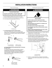
...to children and adults. 1. Position mounting bracket against the wall in death or serious burns to adjust the rear legs from range. 2. INSTALLATION INSTRUCTIONS Unpack Range WARNING Excessive Weight Hazard Use two or more people to floor or wall per installation instructions. Shipping base 4. AD C ... floor or wall. Determine and mark centerline of the determined mounting method. Bracket V-notch 4. Rear leveling leg C. Do not operate range without anti-tip bracket installed and engaged. A A. Failure to do so can result in the cutout so that correspond to lower...
...to children and adults. 1. Position mounting bracket against the wall in death or serious burns to adjust the rear legs from range. 2. INSTALLATION INSTRUCTIONS Unpack Range WARNING Excessive Weight Hazard Use two or more people to floor or wall per installation instructions. Shipping base 4. AD C ... floor or wall. Determine and mark centerline of the determined mounting method. Bracket V-notch 4. Rear leveling leg C. Do not operate range without anti-tip bracket installed and engaged. A A. Failure to do so can result in the cutout so that correspond to lower...
Installation Guide
Page 7
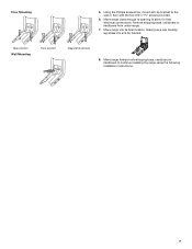
... the wall or floor with the two #12 x 1⁵⁄₈" screws provided. 6. Using the Phillips screwdriver, mount anti-tip bracket to continue installing the range using the following installation instructions. 7 Floor Mounting 5. Move range into its final location, making sure rear leveling leg slides into anti-tip bracket. Move...
... the wall or floor with the two #12 x 1⁵⁄₈" screws provided. 6. Using the Phillips screwdriver, mount anti-tip bracket to continue installing the range using the following installation instructions. 7 Floor Mounting 5. Move range into its final location, making sure rear leveling leg slides into anti-tip bracket. Move...
Installation Guide
Page 8
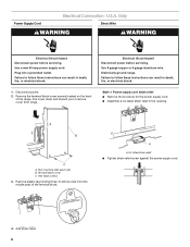
... WARNING Electrical Shock Hazard Disconnect power before servicing. Use a new 40 amp power supply cord. Failure to remove cover from the middle post of the range. Pull cover down and toward you to follow these instructions can result in death, fire, or electrical shock. Electrically ground...
... WARNING Electrical Shock Hazard Disconnect power before servicing. Use a new 40 amp power supply cord. Failure to remove cover from the middle post of the range. Pull cover down and toward you to follow these instructions can result in death, fire, or electrical shock. Electrically ground...
Installation Guide
Page 9
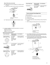
... cm) 3-wire receptacle (NEMA type 10-50R) A UL listed, 250-volt minimum, 40-amp, range power supply cord 3-wire connection: Power supply cord C D A. Ground-link screw C. Part of the range. Removable retaining nut B. Allow enough slack to easily attach the wiring to : 4-wire receptacle (NEMA... type 14-50R) A UL listed, 250-volt minimum, 40-amp, range power supply cord 4-wire connection: Power supply cord 4-wire direct ³⁄₈" (1.0 cm) A circuit breaker 4-wire connection: box or fused ...
... cm) 3-wire receptacle (NEMA type 10-50R) A UL listed, 250-volt minimum, 40-amp, range power supply cord 3-wire connection: Power supply cord C D A. Ground-link screw C. Part of the range. Removable retaining nut B. Allow enough slack to easily attach the wiring to : 4-wire receptacle (NEMA... type 14-50R) A UL listed, 250-volt minimum, 40-amp, range power supply cord 4-wire connection: Power supply cord 4-wire direct ³⁄₈" (1.0 cm) A circuit breaker 4-wire connection: box or fused ...

Installation Guide
Page 10
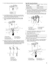
... Ground-link screw C. A B C D D B C A. 10-32 hex nut B. Neutral (white) wire E. large opening , with ring terminals and marked for use with ranges. 5. Securely tighten hex nuts. NOTE: For power supply cord replacement, use only a power cord rated at 250 volts minimum, 40 amps or 50 amps that... is marked for use with nominal 1³⁄₈" (3.5 cm) diameter connection opening, with ring terminals and marked for use with ranges. 8. Ground-link screw D. Connect line 2 (red) and line 1 (black) wires to your electrical supply, make the required 3-wire...
... Ground-link screw C. A B C D D B C A. 10-32 hex nut B. Neutral (white) wire E. large opening , with ring terminals and marked for use with ranges. 5. Securely tighten hex nuts. NOTE: For power supply cord replacement, use only a power cord rated at 250 volts minimum, 40 amps or 50 amps that... is marked for use with nominal 1³⁄₈" (3.5 cm) diameter connection opening, with ring terminals and marked for use with ranges. 8. Ground-link screw D. Connect line 2 (red) and line 1 (black) wires to your electrical supply, make the required 3-wire...
Installation Guide
Page 11
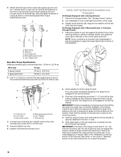
... Setscrew C. Line 1 (black) wire F DE A. Line 2 (red) wire E. Ground-link screw 2. Allow enough slack to easily attach wiring to the range with 10-32 hex nuts. 8. The ground wire must not contact any other terminal. 6. G A B F DE C A. 10-32 hex nut B. ... . (4.0 N-m) 5. A B C G D EF A. Securely tighten setscrew to the terminal block. Terminal lug B. Pull the wires through bottom of range. Ground-link screw C. Cord/conduit plate D. Neutral (white) wire F. Attach terminal lugs to neutral supply wire. 1. Replace terminal block access cover. ...
... Setscrew C. Line 1 (black) wire F DE A. Line 2 (red) wire E. Ground-link screw 2. Allow enough slack to easily attach wiring to the range with 10-32 hex nuts. 8. The ground wire must not contact any other terminal. 6. G A B F DE C A. 10-32 hex nut B. ... . (4.0 N-m) 5. A B C G D EF A. Securely tighten setscrew to the terminal block. Terminal lug B. Pull the wires through bottom of range. Ground-link screw C. Cord/conduit plate D. Neutral (white) wire F. Attach terminal lugs to neutral supply wire. 1. Replace terminal block access cover. ...
Installation Guide
Page 12
... to the center terminal block post with one of terminal lugs. If the rear of the range is not engaged in place by the mounting screws. 4. Slide the range forward and determine if there is inserted into the slot of the User Instructions, for contact ...Terminal lug B. Ground-link screw D. Line 1 (black) F. Replace terminal block access cover. 2. Securely tighten hex nuts. 6. Slide the range forward, and verify that the rear range foot is engaged in . (4.0 N-m) 3. If you need assistance or service, refer to look underneath the bottom of the anti-tip bracket...
... to the center terminal block post with one of terminal lugs. If the rear of the range is not engaged in place by the mounting screws. 4. Slide the range forward and determine if there is inserted into the slot of the User Instructions, for contact ...Terminal lug B. Ground-link screw D. Line 1 (black) F. Replace terminal block access cover. 2. Securely tighten hex nuts. 6. Slide the range forward, and verify that the rear range foot is engaged in . (4.0 N-m) 3. If you need assistance or service, refer to look underneath the bottom of the anti-tip bracket...
Installation Guide
Page 13
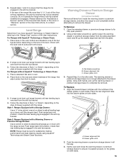
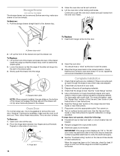
...B 2. then front to contact service. Drawer alignment tab B. Drawer glide notch 2. If the rear of the User Instructions. For Ranges with the range. Style 2: Ranges Equipped with a Warming Drawer or Premium Storage Drawer: Use a wrench or pliers to adjust leveling legs up or down until rear ...section of the Use and Care Guide, or the cover or "Warranty" section of the level. To Remove: 1. If range is not level, pull range forward until the range is removed from the anti-tip bracket. 4. Flat-blade screwdriver B. Align the forward drawer notches with a Storage Drawer: ...
...B 2. then front to contact service. Drawer alignment tab B. Drawer glide notch 2. If the rear of the User Instructions. For Ranges with the range. Style 2: Ranges Equipped with a Warming Drawer or Premium Storage Drawer: Use a wrench or pliers to adjust leveling legs up or down until rear ...section of the Use and Care Guide, or the cover or "Warranty" section of the level. To Remove: 1. If range is not level, pull range forward until the range is removed from the anti-tip bracket. 4. Flat-blade screwdriver B. Align the forward drawer notches with a Storage Drawer: ...
Installation Guide
Page 14
... the steps to open and close. Repeat on . 8. Hinge latch 2. If there is heavy. Dispose of/recycle all the way. 2. Read the "Range Use" section in the Use and Care Guide or User Instructions. Turn power on other side of oven door. Continue to verify the electrical supply.... ■ See the "Troubleshooting" section in the range Use and Care Guide or User Instructions. 7. Slowly push the drawer into the slot in the drawer glide. 3. You should hear a "click" as...
... the steps to open and close. Repeat on . 8. Hinge latch 2. If there is heavy. Dispose of/recycle all the way. 2. Read the "Range Use" section in the Use and Care Guide or User Instructions. Turn power on other side of oven door. Continue to verify the electrical supply.... ■ See the "Troubleshooting" section in the range Use and Care Guide or User Instructions. 7. Slowly push the drawer into the slot in the drawer glide. 3. You should hear a "click" as...
Installation Guide
Page 15
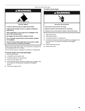
... and adults. Check that the anti-tip bracket is level. Complete cleaning or maintenance. 4. Reconnect power. 15 Check that range is installed and engaged. Replace all parts and panels before servicing. See the "Verify Anti-Tip Bracket Is Installed and Engaged... 6. Complete cleaning or maintenance. 4. Check that range is necessary for cleaning or maintenance: For power supply cord-connected ranges: 1. Slide range forward. 2. Unplug the power supply cord. 3. Re-engage anti-tip bracket if range is moved. Failure to follow these instructions can ...
... and adults. Check that the anti-tip bracket is level. Complete cleaning or maintenance. 4. Reconnect power. 15 Check that range is installed and engaged. Replace all parts and panels before servicing. See the "Verify Anti-Tip Bracket Is Installed and Engaged... 6. Complete cleaning or maintenance. 4. Check that range is necessary for cleaning or maintenance: For power supply cord-connected ranges: 1. Slide range forward. 2. Unplug the power supply cord. 3. Re-engage anti-tip bracket if range is moved. Failure to follow these instructions can ...
Warranty Information
Page 1
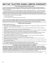
... your major appliance is used in the country in accordance with electrical or plumbing codes, or use your home of the original consumer purchase. MAYTAG® ELECTRIC RANGE LIMITED WARRANTY FIRST YEAR LIMITED WARRANTY (PARTS AND LABOR) For one year from the date of purchase, when this major appliance is installed, operated...
... your major appliance is used in the country in accordance with electrical or plumbing codes, or use your home of the original consumer purchase. MAYTAG® ELECTRIC RANGE LIMITED WARRANTY FIRST YEAR LIMITED WARRANTY (PARTS AND LABOR) For one year from the date of purchase, when this major appliance is installed, operated...
Use & Care Guide
Page 1
...Oven Vent 11 Baking and Roasting 11 Broiling 11 Convection Baking and Roasting (on some models 12 RANGE CARE 13 Clean Cycle 13 General Cleaning 14 Oven Light 15 TROUBLESHOOTING 15 ACCESSORIES 17 WARRANTY 18 ...éctrica" en español, o para obtener información adicional acerca de su producto, visite: www.maytag.com Deberá tener a mano el número de modelo y de serie, que están ubicados en.... You will need assistance, call us at www.maytag.com for purchasing this high-quality product. ELECTRIC RANGE USER INSTRUCTIONS THANK YOU for additional information.
...Oven Vent 11 Baking and Roasting 11 Broiling 11 Convection Baking and Roasting (on some models 12 RANGE CARE 13 Clean Cycle 13 General Cleaning 14 Oven Light 15 TROUBLESHOOTING 15 ACCESSORIES 17 WARRANTY 18 ...éctrica" en español, o para obtener información adicional acerca de su producto, visite: www.maytag.com Deberá tener a mano el número de modelo y de serie, que están ubicados en.... You will need assistance, call us at www.maytag.com for purchasing this high-quality product. ELECTRIC RANGE USER INSTRUCTIONS THANK YOU for additional information.
Use & Care Guide
Page 2
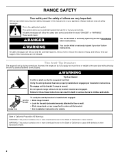
...are not followed. All safety messages will not tip during normal use. The Anti-Tip Bracket The range will tell you what the potential hazard is, tell you how to reduce the chance of injury..., and tell you what can kill or hurt you don't follow these instructions can tip the range and be killed or seriously injured if you apply too much force or weight to cause cancer.... Verify the anti-tip bracket has been properly installed and engaged per installation instructions. Range Foot To verify the anti-tip bracket is moved. This symbol alerts you to children and adults....
...are not followed. All safety messages will not tip during normal use. The Anti-Tip Bracket The range will tell you what the potential hazard is, tell you how to reduce the chance of injury..., and tell you what can kill or hurt you don't follow these instructions can tip the range and be killed or seriously injured if you apply too much force or weight to cause cancer.... Verify the anti-tip bracket has been properly installed and engaged per installation instructions. Range Foot To verify the anti-tip bracket is moved. This symbol alerts you to children and adults....
Use & Care Guide
Page 3
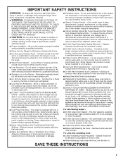
...time to cool. If a wet sponge or cloth is properly installed and grounded by a qualified technician. ■ Never Use the Range for range-top service without breaking due to the sudden change in color. Some cleaners can produce noxious fumes if applied to cover the surface.... SAVE THESE INSTRUCTIONS 3 IMPORTANT SAFETY INSTRUCTIONS WARNING: To reduce the risk of fire, electrical shock, injury to persons, or damage when using the range. ■ User Servicing - children climbing on a hot cooking area, be seriously injured. ■ Proper Installation - They should be stored in ...
...time to cool. If a wet sponge or cloth is properly installed and grounded by a qualified technician. ■ Never Use the Range for range-top service without breaking due to the sudden change in color. Some cleaners can produce noxious fumes if applied to cover the surface.... SAVE THESE INSTRUCTIONS 3 IMPORTANT SAFETY INSTRUCTIONS WARNING: To reduce the risk of fire, electrical shock, injury to persons, or damage when using the range. ■ User Servicing - children climbing on a hot cooking area, be seriously injured. ■ Proper Installation - They should be stored in ...
Use & Care Guide
Page 4
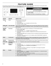
... when finished. 4 The oven light is off ) START CANCEL TEMP/TIME BAKE BROIL FEATURE Clock Oven cavity light Oven timer Cooking start Range function Temperature and time adjust Baking and roasting Broiling INSTRUCTIONS The Clock uses a 12-hour cycle. 1. WARNING Food Poisoning Hazard Do not ... 1. The Cancel keypad stops any oven function. Press START, and allow oven to take effect. 5. The oven light will sound at www.maytag.com for the change to preheat for 5 seconds. Press BAKE. 2. FEATURE GUIDE This manual covers several models. Your model may have some or...
... when finished. 4 The oven light is off ) START CANCEL TEMP/TIME BAKE BROIL FEATURE Clock Oven cavity light Oven timer Cooking start Range function Temperature and time adjust Baking and roasting Broiling INSTRUCTIONS The Clock uses a 12-hour cycle. 1. WARNING Food Poisoning Hazard Do not ... 1. The Cancel keypad stops any oven function. Press START, and allow oven to take effect. 5. The oven light will sound at www.maytag.com for the change to preheat for 5 seconds. Press BAKE. 2. FEATURE GUIDE This manual covers several models. Your model may have some or...


