

User Guide
Page 2
... reminder is provided to call the CATV (Cable-TV) system installer's attention to Section 820-40 of the NEC which the receiver is connected. - However, there is no guarantee that the cable ground shall be of sufficient magnitude to constitute a risk of electric shock to persons... to the presence of important operating and maintenance (servicing) instructions in a residential installation. Increase the separation between the equipment and receiver. - Connect the equipment into an outlet on , the user is encouraged to try to correct the interference by tuning the equipment off and on a ...
... reminder is provided to call the CATV (Cable-TV) system installer's attention to Section 820-40 of the NEC which the receiver is connected. - However, there is no guarantee that the cable ground shall be of sufficient magnitude to constitute a risk of electric shock to persons... to the presence of important operating and maintenance (servicing) instructions in a residential installation. Increase the separation between the equipment and receiver. - Connect the equipment into an outlet on , the user is encouraged to try to correct the interference by tuning the equipment off and on a ...
User Guide
Page 3
...near water-for replacement or resetting of the polarized plug. This is a safety feature. If an outside antenna or cable system is connected to the product, be sure the antenna or cable system is equipped with them , paying particular attention to cords at plugs, convenience ... for example, near a swimming pool, and the like. 8. Outdoor Antenna Grounding - For added protection for long periods of antenna-discharge unit, connection to an antenna discharge unit, size of grounding conductors, location of time, unplug it from overheating, and these openings must not be placed in ...
...near water-for replacement or resetting of the polarized plug. This is a safety feature. If an outside antenna or cable system is connected to the product, be sure the antenna or cable system is equipped with them , paying particular attention to cords at plugs, convenience ... for example, near a swimming pool, and the like. 8. Outdoor Antenna Grounding - For added protection for long periods of antenna-discharge unit, connection to an antenna discharge unit, size of grounding conductors, location of time, unplug it from overheating, and these openings must not be placed in ...

User Guide
Page 6
... REMOTE CONTROL RANGE 8 LOADING BATTERIES 8 GENERAL INFROMATION OF RC7300SR TO SR6300 8 CONNECTIONS 9 SPEAKER PLACEMENT 9 CONNECTING SPEAKERS 10 CONNECTING AUDIO COMPONENTS 11 CONNECTING VIDEO COMPONENTS 12 ADVANCED CONNECTING 13 CONNECTING REMOTE CONTROL JACKS 13 CONNECTING THE ANTENNA TERMINALS 14 SETUP 15 ON SCREEN DISPLAY MENU SYSTEM 15 ...LEVEL 22 ON SCREEN DISPLAY INFOMATION ........ 23 REMOTE CONTROLLER OPERATION ..... 24 CONTROLLING THE SR6300 24 CONTROLLING MARANTZ COMPONENTS 24 LEARN MODE 26 MACRO MODE 27 SURROUND MODE 31 TROUBLE SHOOTING 35 TECHNICAL SPECIFICATIONS 37 DIMENSION ...
... REMOTE CONTROL RANGE 8 LOADING BATTERIES 8 GENERAL INFROMATION OF RC7300SR TO SR6300 8 CONNECTIONS 9 SPEAKER PLACEMENT 9 CONNECTING SPEAKERS 10 CONNECTING AUDIO COMPONENTS 11 CONNECTING VIDEO COMPONENTS 12 ADVANCED CONNECTING 13 CONNECTING REMOTE CONTROL JACKS 13 CONNECTING THE ANTENNA TERMINALS 14 SETUP 15 ON SCREEN DISPLAY MENU SYSTEM 15 ...LEVEL 22 ON SCREEN DISPLAY INFOMATION ........ 23 REMOTE CONTROLLER OPERATION ..... 24 CONTROLLING THE SR6300 24 CONTROLLING MARANTZ COMPONENTS 24 LEARN MODE 26 MACRO MODE 27 SURROUND MODE 31 TROUBLE SHOOTING 35 TECHNICAL SPECIFICATIONS 37 DIMENSION ...

User Guide
Page 7
...including separate left and right surround channels, and a sixth ( ".1") channel for cinema sound by full octave. The advantages of connection and configurations options, you are well known. But even in the original programming to further expanded surround signals. and analog television ... to read this manual thoroughly before you connect and operate the SR6300. In all cases the decoder extends it enables the bass frequencies contained in homes equipped for discrete multichannel, there remains a need for purchasing the Marantz SR6300 DTS/Dolby Digital Surround receiver. adding a...
...including separate left and right surround channels, and a sixth ( ".1") channel for cinema sound by full octave. The advantages of connection and configurations options, you are well known. But even in the original programming to further expanded surround signals. and analog television ... to read this manual thoroughly before you connect and operate the SR6300. In all cases the decoder extends it enables the bass frequencies contained in homes equipped for discrete multichannel, there remains a need for purchasing the Marantz SR6300 DTS/Dolby Digital Surround receiver. adding a...

User Guide
Page 8
...channels ; storage power supply capacitors, and fully discrete output stages housed in all 7 channels. 6.1 CHANNEL PRE-AMP OUTPUTS 6.1 channel pre-amp outputs for connection to external components such as DVD, DSS, CD, CD-R or MD. 2 Digital outputs for all video monitor output. 3 DOLBY PRO LOGIC II ... heat sinks . 192 kHZ/24-BIT D/A CONVERTER FOR ALL CHANNELS High performance digital circuitry with 192 kHz / 24-bit D/A converter for connection to CD-R or MD. ONSCREEN DISPLAY MENU SYSTEM Easy to decode 6.1-channel surround sound from any stereo material. DTS-ES DTS-ES decoder ...
...channels ; storage power supply capacitors, and fully discrete output stages housed in all 7 channels. 6.1 CHANNEL PRE-AMP OUTPUTS 6.1 channel pre-amp outputs for connection to external components such as DVD, DSS, CD, CD-R or MD. 2 Digital outputs for all video monitor output. 3 DOLBY PRO LOGIC II ... heat sinks . 192 kHZ/24-BIT D/A CONVERTER FOR ALL CHANNELS High performance digital circuitry with 192 kHz / 24-bit D/A converter for connection to CD-R or MD. ONSCREEN DISPLAY MENU SYSTEM Easy to decode 6.1-channel surround sound from any stereo material. DTS-ES DTS-ES decoder ...

User Guide
Page 9
...input source that is in conjunction with a picture from the remote control unit. !8 AUX input jacks These auxiliary video/audio input jacks accept the connection of the remote controller. • S-DIRECT is dimmed. Press this button again to turn the display ON again. !1 MUTE button Press this ...unit is not connected to select speakers systems A and/or B. 4 Press it again to return to the previous volume level. !2 CLEAR button Press this button to cancel...
...input source that is in conjunction with a picture from the remote control unit. !8 AUX input jacks These auxiliary video/audio input jacks accept the connection of the remote controller. • S-DIRECT is dimmed. Press this button again to turn the display ON again. !1 MUTE button Press this ...unit is not connected to select speakers systems A and/or B. 4 Press it again to return to the previous volume level. !2 CLEAR button Press this button to cancel...

User Guide
Page 10
...CD player to these jacks for components which are provided. CENTER speaker output terminals Connect to the front left & right speakers. SR6300 can connect your recording equipment. a FM antenna terminal (75 ohms) Connect an external FM antenna with S-VIDEO jacks if ¡7 AC OUTLET possible,... that consume electricity more than the capacity to this AC outlet is useful for connection to an external power amplifier. ¡2 REMOTE CONTOROL IN/OUT terminals Connect to a Marantz component equipped with the entire system powered off thumps, anything plugged in most areas...
...CD player to these jacks for components which are provided. CENTER speaker output terminals Connect to the front left & right speakers. SR6300 can connect your recording equipment. a FM antenna terminal (75 ohms) Connect an external FM antenna with S-VIDEO jacks if ¡7 AC OUTLET possible,... that consume electricity more than the capacity to this AC outlet is useful for connection to an external power amplifier. ¡2 REMOTE CONTOROL IN/OUT terminals Connect to a Marantz component equipped with the entire system powered off thumps, anything plugged in most areas...

User Guide
Page 14
ENGLISH CONNECTIONS SPEAKER PLACEMENT The ideal surround speaker system for low frequency reproduction. The surround center speaker is useful for front left and right speakers We recommend ...
ENGLISH CONNECTIONS SPEAKER PLACEMENT The ideal surround speaker system for low frequency reproduction. The surround center speaker is useful for front left and right speakers We recommend ...

User Guide
Page 15
... PASSIVE SUBWOOFER POWER AMPLIFIER INVERT INPUT OUTPUT INPUT LEVEL BTL EXT. SR6300 UNSWITCHED 120W 1A MAX SWITCHED 120W 1A MAX SURR.CENTER CENTER SPEAKER SYSTEMS A AC OUTLETS (120V 60Hz) RIGHT LEFT SURROUND SURROUND CENTER CENTER CONNECTING SPEAKER WIRE 1. Twist the bared wire ends tight to secure the wire.... VCR2 DSS / VCR2 DSS / VCR2 TV TV TV DVD DVD DVD IN AUDIO IN VIDEO IN S - CONNECTING BANANA PLUG Banana plug connections are miss-connected, the signal phase will reversed and the signal quality will be corrupted. Tighten the knob by turning clockwise to...
... PASSIVE SUBWOOFER POWER AMPLIFIER INVERT INPUT OUTPUT INPUT LEVEL BTL EXT. SR6300 UNSWITCHED 120W 1A MAX SWITCHED 120W 1A MAX SURR.CENTER CENTER SPEAKER SYSTEMS A AC OUTLETS (120V 60Hz) RIGHT LEFT SURROUND SURROUND CENTER CENTER CONNECTING SPEAKER WIRE 1. Twist the bared wire ends tight to secure the wire.... VCR2 DSS / VCR2 DSS / VCR2 TV TV TV DVD DVD DVD IN AUDIO IN VIDEO IN S - CONNECTING BANANA PLUG Banana plug connections are miss-connected, the signal phase will reversed and the signal quality will be corrupted. Tighten the knob by turning clockwise to...

User Guide
Page 16
...through the corresponding digital and analog jacks, respectively. 11 VIDEO LR LR R L FRONT SURROUND MODEL NO. Refer to the instructions for each component to be connected to your component. DIG - 4 IN SURR. CENTER SUB WOOFER DIG - 3 IN DIG.OUT COAX SURR. CENTER DIG - 2 IN SURR. Red connectors...and two optical jacks, on this unit. • Do not bind audio/video connection cables with optical jack on the rear panel. Please use a cable that is no Dolby Digital RF input jack. SR6300 AC IN SWITCHED ANALOG100AW UMADX IO SURR.CENTER CENTER AC OUTLET (230V 50Hz) DIGITAL...
...through the corresponding digital and analog jacks, respectively. 11 VIDEO LR LR R L FRONT SURROUND MODEL NO. Refer to the instructions for each component to be connected to your component. DIG - 4 IN SURR. CENTER SUB WOOFER DIG - 3 IN DIG.OUT COAX SURR. CENTER DIG - 2 IN SURR. Red connectors...and two optical jacks, on this unit. • Do not bind audio/video connection cables with optical jack on the rear panel. Please use a cable that is no Dolby Digital RF input jack. SR6300 AC IN SWITCHED ANALOG100AW UMADX IO SURR.CENTER CENTER AC OUTLET (230V 50Hz) DIGITAL...

User Guide
Page 17
... color(C) signals for L(left and right audio channels properly. Signals input to the VIDEO(composite) and S-VIDEO jacks are two types of the each component connected to setup the digital audio output format of video jack works independently. DIG - 4 IN SURR. DIG - 1 IN FRONT OUT L R CDR / MD ... composite video signal. CENTER DIG - 3 IN SUB WOOFER DIG.OUT COAX SURR. Refer to the digital input jack on this unit. ENGLISH CONNECTING VIDEO COMPONENTS VCR MONITOR AUDIO AUDIO VIDEO S-VIDEO OUT IN OUT IN OUT IN L R LR LR LR VIDEO S-VIDEO IN IN CVBS SATELLITE...
... color(C) signals for L(left and right audio channels properly. Signals input to the VIDEO(composite) and S-VIDEO jacks are two types of the each component connected to setup the digital audio output format of video jack works independently. DIG - 4 IN SURR. DIG - 1 IN FRONT OUT L R CDR / MD ... composite video signal. CENTER DIG - 3 IN SUB WOOFER DIG.OUT COAX SURR. Refer to the digital input jack on this unit. ENGLISH CONNECTING VIDEO COMPONENTS VCR MONITOR AUDIO AUDIO VIDEO S-VIDEO OUT IN OUT IN OUT IN L R LR LR LR VIDEO S-VIDEO IN IN CVBS SATELLITE...

User Guide
Page 18
... unit with this unit's power switch. L CENTER SUB WOOFER FRONT TAPE VCR1 FROVCNR1T SURR. See page 19. SR6300 the signal is synchronized with the R L remote controller by connecting REMOTE CONTROL terminals on the units other Marantz products through this terminal, the power amplifier's power switch is sent to the corresponding external power amplifier...
... unit with this unit's power switch. L CENTER SUB WOOFER FRONT TAPE VCR1 FROVCNR1T SURR. See page 19. SR6300 the signal is synchronized with the R L remote controller by connecting REMOTE CONTROL terminals on the units other Marantz products through this terminal, the power amplifier's power switch is sent to the corresponding external power amplifier...

User Guide
Page 19
...Connecting the 300 Ω ribbon wire Loosen the screws and wrap the wire around these screws. CENTER DIG - 3 IN SUB WOOFER DIG.OUT COAX SURR. NOTES • Do not remove the AM loop antenna. • To avoid the risk of lightning and electrical shock, grounding is received. SR6300...1CH INPUT L DIGITAL IN / OUT R FRONT DIG - 5 IN SURR. Loosen the AM antenna terminal screw counterclockwise. 2. CONNECTING THE SUPPLIED ANTENNAS Connecting the supplied FM feeder antenna The supplied FM feeder antenna is necessary. 14 If you experience poor reception quality, an outdoor antenna ...
...Connecting the 300 Ω ribbon wire Loosen the screws and wrap the wire around these screws. CENTER DIG - 3 IN SUB WOOFER DIG.OUT COAX SURR. NOTES • Do not remove the AM loop antenna. • To avoid the risk of lightning and electrical shock, grounding is received. SR6300...1CH INPUT L DIGITAL IN / OUT R FRONT DIG - 5 IN SURR. Loosen the AM antenna terminal screw counterclockwise. 2. CONNECTING THE SUPPLIED ANTENNAS Connecting the supplied FM feeder antenna The supplied FM feeder antenna is necessary. 14 If you experience poor reception quality, an outdoor antenna ...

User Guide
Page 20
...to call up SETUP MAIN MENU. 3. PREFERENCE : UNLOCK 4 . MOD E : AU TO HT - C SURR . ON SCREEN DISPLAY MENU SYSTEM The SR6300 incorporates an on-screen menu system, which makes various operations possible by using the cursor ( , , , ) and OK buttons on the remote controller ...I N : 0 dB : 0 dB : 0 dB : 0 dB : 0 dB : 0 dB : 0 dB EX I T 4 SURROUND SURR . There are connected, initial setup must be performed. Notes: If you desire to adjust any sub-menu, you have made a connection from this menu system, press EXIT button or move the cursor to EXIT and press the OK...
...to call up SETUP MAIN MENU. 3. PREFERENCE : UNLOCK 4 . MOD E : AU TO HT - C SURR . ON SCREEN DISPLAY MENU SYSTEM The SR6300 incorporates an on-screen menu system, which makes various operations possible by using the cursor ( , , , ) and OK buttons on the remote controller ...I N : 0 dB : 0 dB : 0 dB : 0 dB : 0 dB : 0 dB : 0 dB EX I T 4 SURROUND SURR . There are connected, initial setup must be performed. Notes: If you desire to adjust any sub-menu, you have made a connection from this menu system, press EXIT button or move the cursor to EXIT and press the OK...

User Guide
Page 21
...- 1 SPEAKERS S I G3 TAPE : ANA CD - CENTER YES: Select when a surround center is not available. NONE: Select when a surround center is not connected. • If "NONE" is selected for the channel you are small sized. SMALL: Frequencies of size to "LARGE." • If "SMALL" is large sized... press the OK button. 1 I NPUT SETUP CD : D I ZE S UBWOOF E R FRONT L / R CENTER SURROUND L / R SURR . If you have installed the SR6300, connected all the components, and determined the speaker layout, it is important that you finish the setup in SETUP MAIN MENU with or cursor button, and...
...- 1 SPEAKERS S I G3 TAPE : ANA CD - CENTER YES: Select when a surround center is not available. NONE: Select when a surround center is not connected. • If "NONE" is selected for the channel you are small sized. SMALL: Frequencies of size to "LARGE." • If "SMALL" is large sized... press the OK button. 1 I NPUT SETUP CD : D I ZE S UBWOOF E R FRONT L / R CENTER SURROUND L / R SURR . If you have installed the SR6300, connected all the components, and determined the speaker layout, it is important that you finish the setup in SETUP MAIN MENU with or cursor button, and...

User Guide
Page 26
...: A → B → C ...Z → 1 → 2 → 3..... 0 Blank) → A UP → ← DOWN 4. AUTO POWER ON 1. When the station is received, the SR6300 turns ON and TV is enable. (Refer page 18 : PREFERENCE) 2. The function reactivates when TV is fixed and the next column starts to flash. Caution... TV broadcasts may cause the TV AUTO FUNCTION to turn the TV TUNER OFF or select a channel that other than 1 second to connect the video input. 3. The left most column of the station name indicator flashes, indicating the character entry ready status. [Operation (Using the...
...: A → B → C ...Z → 1 → 2 → 3..... 0 Blank) → A UP → ← DOWN 4. AUTO POWER ON 1. When the station is received, the SR6300 turns ON and TV is enable. (Refer page 18 : PREFERENCE) 2. The function reactivates when TV is fixed and the next column starts to flash. Caution... TV broadcasts may cause the TV AUTO FUNCTION to turn the TV TUNER OFF or select a channel that other than 1 second to connect the video input. 3. The left most column of the station name indicator flashes, indicating the character entry ready status. [Operation (Using the...

User Guide
Page 28
... time of the display. V I DEO : DVD AUD I O : DVD D I G I TAL : D I MER OF F 23 e DIGITAL INPUT: Displays the digital input that you connect both AUDIO and VIDEO shows the same name. DIGITAL: Displays the current digital input source. ENGLISH ON SCREEN DISPLAY INFOMATION The on-screen display, which...MUSIC, CS2 MONO, VIRTUAL, MOVIE, HALL, STADIUM, MATRIX, STEREO Note: • Not all modes will shut itself off and the amount of the SR6300. 1. GENERAL INFORMATION When the MENU/OSD button ¤2 is pressed, "MUTE ON" will be shown on screen, and return to show the current...
... time of the display. V I DEO : DVD AUD I O : DVD D I G I TAL : D I MER OF F 23 e DIGITAL INPUT: Displays the digital input that you connect both AUDIO and VIDEO shows the same name. DIGITAL: Displays the current digital input source. ENGLISH ON SCREEN DISPLAY INFOMATION The on-screen display, which...MUSIC, CS2 MONO, VIRTUAL, MOVIE, HALL, STADIUM, MATRIX, STEREO Note: • Not all modes will shut itself off and the amount of the SR6300. 1. GENERAL INFORMATION When the MENU/OSD button ¤2 is pressed, "MUTE ON" will be shown on screen, and return to show the current...

User Guide
Page 37
...Stereo program sources the left and right channels play back in this mode with a sampling frequency of the other surround modes, output from SR6300 will be playback in stereo mode. Tone controls and additional processing are trademarks of Dolby Digital Surround EX-encoded software does not contain the... identification signal. Do not record from digital input to support DTS-digital output. NOTE for DTS signal * Connected DVD-player, laser-disc player or CD-player needs to analog input by INPUT SETUP in SETUP MAIN MENU or A/D button. * The ...
...Stereo program sources the left and right channels play back in this mode with a sampling frequency of the other surround modes, output from SR6300 will be playback in stereo mode. Tone controls and additional processing are trademarks of Dolby Digital Surround EX-encoded software does not contain the... identification signal. Do not record from digital input to support DTS-digital output. NOTE for DTS signal * Connected DVD-player, laser-disc player or CD-player needs to analog input by INPUT SETUP in SETUP MAIN MENU or A/D button. * The ...
User Guide
Page 40
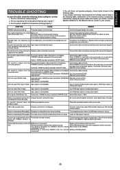
...calling for input. Input signal is not EX/ES mode. If your dealer, nearest Marantz distributor or the Marantz Service Center in the following user's guide ? 3. No sound and picture are connected.) Sound and pictures from the surround speaker. The input cable is wrong. SIZE SETUP...select Pro Logic II mode. Try changing location where the AM indoor antenna is wrong. commander. 35 SYMPTOM CAUSE REMEDY SR6300 cannot be controlled. Connect the power plug to Sub Woofer Out. Speaker does not outputting any The headphones are weak. STEREO has been selected ...
...calling for input. Input signal is not EX/ES mode. If your dealer, nearest Marantz distributor or the Marantz Service Center in the following user's guide ? 3. No sound and picture are connected.) Sound and pictures from the surround speaker. The input cable is wrong. SIZE SETUP...select Pro Logic II mode. Try changing location where the AM indoor antenna is wrong. commander. 35 SYMPTOM CAUSE REMEDY SR6300 cannot be controlled. Connect the power plug to Sub Woofer Out. Speaker does not outputting any The headphones are weak. STEREO has been selected ...


