
Owner s Manual In English
Page 2
... connectors 24 10 Performing operations by RC on this unit without visual contact 24 12 Remotely connecting Marantz audio devices 24 Connecting the power cord 25 Playback Turning the power on 27 Selecting the speakers for audio output 28 Selecting the input source 28 Adjusting the volume 28 Turning off the sound...
... connectors 24 10 Performing operations by RC on this unit without visual contact 24 12 Remotely connecting Marantz audio devices 24 Connecting the power cord 25 Playback Turning the power on 27 Selecting the speakers for audio output 28 Selecting the input source 28 Adjusting the volume 28 Turning off the sound...
Owner s Manual In English
Page 6
The Marantz Super Audio CD player uses the Cirrus Logic CS4398, which is possible... Digital Input (Coaxial, Optical 1/2) This unit has a digital input terminal that allows input of speakers (Speakers A and Speakers B), you can connect to bi-wiring speakers with separate input terminals for connecting turntables This unit is provided with a phono amplifier so that signals... a turntable and play records (Only the MM cartridge can be used) (v p. 21) 0 Two-sets of speaker output terminals In addition to using two sets of digital audio from external devices such as minimized signal path, use ...
The Marantz Super Audio CD player uses the Cirrus Logic CS4398, which is possible... Digital Input (Coaxial, Optical 1/2) This unit has a digital input terminal that allows input of speakers (Speakers A and Speakers B), you can connect to bi-wiring speakers with separate input terminals for connecting turntables This unit is provided with a phono amplifier so that signals... a turntable and play records (Only the MM cartridge can be used) (v p. 21) 0 Two-sets of speaker output terminals In addition to using two sets of digital audio from external devices such as minimized signal path, use ...

Owner s Manual In English
Page 9
...DIRECT mode on/off. (v p. 29) I TREBLE control knob This setting adjusts the volume level for the treble. (v p. 28) J Speaker switching buttons/indicators (SPEAKERS A/B) These select the speaker for audio output. (v p. 28) K LOUDNESS button/indicator This turns the LOUDNESS mode on/off. (v p. 29) L BALANCE control ...knob This adjusts the balance of the volume output from the left and right speakers. (v p. 28) M Remote control sensor This receives signals from the remote control unit. (v p. 5) 0 7, 9, a and b can be adjusted when...
...DIRECT mode on/off. (v p. 29) I TREBLE control knob This setting adjusts the volume level for the treble. (v p. 28) J Speaker switching buttons/indicators (SPEAKERS A/B) These select the speaker for audio output. (v p. 28) K LOUDNESS button/indicator This turns the LOUDNESS mode on/off. (v p. 29) L BALANCE control ...knob This adjusts the balance of the volume output from the left and right speakers. (v p. 28) M Remote control sensor This receives signals from the remote control unit. (v p. 5) 0 7, 9, a and b can be adjusted when...

Owner s Manual In English
Page 10
... q Connections w Playback Settings Tips e rt Appendix y u i o . E Remote control input/output connectors (REMOTE CONTROL) Used to connect to a Marantz audio device that is compatible with a TV or digital audio connector. (v p. 23) C Speaker terminals (SPEAKERS) Used to connect speakers. (v p. 18) D FLASHER IN jack Used when using a control BOX or other such control devices to connect a device...
... q Connections w Playback Settings Tips e rt Appendix y u i o . E Remote control input/output connectors (REMOTE CONTROL) Used to connect to a Marantz audio device that is compatible with a TV or digital audio connector. (v p. 23) C Speaker terminals (SPEAKERS) Used to connect speakers. (v p. 18) D FLASHER IN jack Used when using a control BOX or other such control devices to connect a device...

Owner s Manual In English
Page 17
Contents Connections Playback o Contents Connecting speakers 18 Connecting a playback device 21 Connecting a recording device 22 Connecting a TV/Devices with digital audio connectors 23 Connecting devices with connection cables. Front panel Rear ... completed. 0 Do not bundle power cords together with remote control connectors 24 Connecting the power cord 25 NOTE 0 Do not plug in humming or noise. Speaker cable Coaxial digital cable Optical cable Audio cable L L R R Remote connector cable .... .
Contents Connections Playback o Contents Connecting speakers 18 Connecting a playback device 21 Connecting a recording device 22 Connecting a TV/Devices with digital audio connectors 23 Connecting devices with connection cables. Front panel Rear ... completed. 0 Do not bundle power cords together with remote control connectors 24 Connecting the power cord 25 NOTE 0 Do not plug in humming or noise. Speaker cable Coaxial digital cable Optical cable Audio cable L L R R Remote connector cable .... .

Owner s Manual In English
Page 18
... Index sides touch each other. ("Protection circuit" (v p. 43)) 0 Never touch the speaker terminals while the power cord is connected. of connected speakers Speaker Impedance SPEAKERS A (Standard connection) 2 (one set) 4 - 16 Ω/ohms SPEAKERS B 2 (one set) 4 - 16 Ω/ohms SPEAKERS A and SPEAKERS B 4 (two sets) 8 - 16 Ω/ohms SPEAKERS A and SPEAKERS B (Bi-wiring connection) 2 (one set) 4 - 16 Ω/ohms Settings Tips...
... Index sides touch each other. ("Protection circuit" (v p. 43)) 0 Never touch the speaker terminals while the power cord is connected. of connected speakers Speaker Impedance SPEAKERS A (Standard connection) 2 (one set) 4 - 16 Ω/ohms SPEAKERS B 2 (one set) 4 - 16 Ω/ohms SPEAKERS A and SPEAKERS B 4 (two sets) 8 - 16 Ω/ohms SPEAKERS A and SPEAKERS B (Bi-wiring connection) 2 (one set) 4 - 16 Ω/ohms Settings Tips...

Owner s Manual In English
Page 19
When only one set of terminals, and a total of two sets of speakers can be connected to each set of speaker terminals (SPEAKER A and SPEAKER B). Front panel Rear panel Remote control 19 unit Index One set of speakers can be connected, use either the SPEAKERS A or SPEAKERS B terminals. SPEAKERS A (L) (R) w qw q SPEAKERS B (L) wq (R) wq . The same signal is equipped with two sets of speakers is to be connected. Contents Connections Playback Settings Tips Appendix Speaker A/B connection This unit is output from the SPEAKERS A and SPEAKERS B terminals.
When only one set of terminals, and a total of two sets of speakers can be connected to each set of speaker terminals (SPEAKER A and SPEAKER B). Front panel Rear panel Remote control 19 unit Index One set of speakers can be connected, use either the SPEAKERS A or SPEAKERS B terminals. SPEAKERS A (L) (R) w qw q SPEAKERS B (L) wq (R) wq . The same signal is equipped with two sets of speakers is to be connected. Contents Connections Playback Settings Tips Appendix Speaker A/B connection This unit is output from the SPEAKERS A and SPEAKERS B terminals.

Owner s Manual In English
Page 20
... Appendix Bi-wiring connection This connection limits the effects of signal interference between the high range speakers (tweeters) and low range speakers (woofers), allowing you to SPEAKERS B (or SPEAKERS A). Speaker (R) HIGH wq LOW wq Remove shorting bar Remove shorting bar Speaker (L) HIGH wq LOW wq Remove shorting bar Remove shorting bar . When bi-wiring with bi...
... Appendix Bi-wiring connection This connection limits the effects of signal interference between the high range speakers (tweeters) and low range speakers (woofers), allowing you to SPEAKERS B (or SPEAKERS A). Speaker (R) HIGH wq LOW wq Remove shorting bar Remove shorting bar Speaker (L) HIGH wq LOW wq Remove shorting bar Remove shorting bar . When bi-wiring with bi...

Owner s Manual In English
Page 21
... for safety grounding purposes. If you set this unit. Note that depending on the turntable, connecting the ground line may hear a hum noise from the speakers. Contents Connections Playback Settings Tips Appendix Connecting a playback device You can be reduced. When you may have the reverse effect of increasing noise. Turntable Tuner...
... for safety grounding purposes. If you set this unit. Note that depending on the turntable, connecting the ground line may hear a hum noise from the speakers. Contents Connections Playback Settings Tips Appendix Connecting a playback device You can be reduced. When you may have the reverse effect of increasing noise. Turntable Tuner...

Owner s Manual In English
Page 23
This causes noise and could damage the speakers. Front panel Rear panel Remote control 23 unit Index Contents Connections Playback Settings Tips Appendix Connecting a TV/Devices with a sampling frequency of this device. 0 Do ...
This causes noise and could damage the speakers. Front panel Rear panel Remote control 23 unit Index Contents Connections Playback Settings Tips Appendix Connecting a TV/Devices with a sampling frequency of this device. 0 Do ...

Owner s Manual In English
Page 26
Contents Connections Playback o Contents Turning the power on 27 Selecting the speakers for audio output 28 Selecting the input source 28 Adjusting the volume 28 Turning off the sound temporarily (Muting) 28 Adjusting the tone 28 Playing CDs 29 Connect and playback from a digital device (Coaxial/Optical) 30 Recording 31 Settings Tips Appendix Front panel Rear panel Remote control 26 unit Index
Contents Connections Playback o Contents Turning the power on 27 Selecting the speakers for audio output 28 Selecting the input source 28 Adjusting the volume 28 Turning off the sound temporarily (Muting) 28 Adjusting the tone 28 Playing CDs 29 Connect and playback from a digital device (Coaxial/Optical) 30 Recording 31 Settings Tips Appendix Front panel Rear panel Remote control 26 unit Index

Owner s Manual In English
Page 27
Contents Connections Playback Input source select buttons SOURCE DIRECT MUTE AMP POWER X VOLUME df SOURCE DIRECT INPUT SELECTOR SPEAKERS A/B LOUDNESS Settings Tips Appendix Turning the power on 1 Press X on the main unit to turn the INPUT SELECTOR when the unit is in standby mode ...
Contents Connections Playback Input source select buttons SOURCE DIRECT MUTE AMP POWER X VOLUME df SOURCE DIRECT INPUT SELECTOR SPEAKERS A/B LOUDNESS Settings Tips Appendix Turning the power on 1 Press X on the main unit to turn the INPUT SELECTOR when the unit is in standby mode ...

Owner s Manual In English
Page 28
Selecting the input source 1 Press the input source select button to be used for audio output 1 Press SPEAKERS A/B to select the speaker system to be played back. Front panel Rear panel Remote control 28 unit Index The SOURCE DIRECT indicator turns off. 2 Turn the BASS, TREBLE ...VOLUME on the main unit. The indicator of the indicators and turn off source direct mode. 1 Use VOLUME df to turn audio output from the speaker terminals off all of the selected input source lights. 0 You can also adjust the master volume by turning INPUT SELECTOR on the main unit. The...
Selecting the input source 1 Press the input source select button to be used for audio output 1 Press SPEAKERS A/B to select the speaker system to be played back. Front panel Rear panel Remote control 28 unit Index The SOURCE DIRECT indicator turns off. 2 Turn the BASS, TREBLE ...VOLUME on the main unit. The indicator of the indicators and turn off source direct mode. 1 Use VOLUME df to turn audio output from the speaker terminals off all of the selected input source lights. 0 You can also adjust the master volume by turning INPUT SELECTOR on the main unit. The...
Owner s Manual In English
Page 30
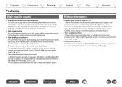
... digital device connected to this unit cannot detect the sampling frequency of supported audio formats See "D/A converter" (v p. 43). This causes noise and could damage the speakers. 0 If the sampling frequency switches, such as Dolby Digital, and DTS. Settings Tips Appendix o Specifications of the input signal. 4 Use VOLUME df to B mode in...
... digital device connected to this unit cannot detect the sampling frequency of supported audio formats See "D/A converter" (v p. 43). This causes noise and could damage the speakers. 0 If the sampling frequency switches, such as Dolby Digital, and DTS. Settings Tips Appendix o Specifications of the input signal. 4 Use VOLUME df to B mode in...

Owner s Manual In English
Page 34
... function of the currently set input source flashes in blue three times. The indicator of the remote control unit 1 Press SPEAKERS A for approximately 5 seconds to disable the remote control signal receiving function. By default, this unit. Disabling the remote signal... receiving function of the remote control unit 1 Press SPEAKERS B for approximately 5 seconds to enable the remote control signal receiving function. When the function is enabled. Contents Connections Playback Settings ...
... function of the currently set input source flashes in blue three times. The indicator of the remote control unit 1 Press SPEAKERS A for approximately 5 seconds to disable the remote control signal receiving function. By default, this unit. Disabling the remote signal... receiving function of the remote control unit 1 Press SPEAKERS B for approximately 5 seconds to enable the remote control signal receiving function. When the function is enabled. Contents Connections Playback Settings ...
Owner s Manual In English
Page 39
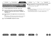
... the connector and came in contact with each other devices operating properly? The protection circuit may have been activated because speaker cable core wires came in this unit does not operate properly, check the corresponding symptoms in a place having good ventilation. 0 Check ...the speaker connections. Contents Connections Playback Settings Tips Appendix Troubleshooting If a problem should arise, first check the following: 1. Is the set being...
... the connector and came in contact with each other devices operating properly? The protection circuit may have been activated because speaker cable core wires came in this unit does not operate properly, check the corresponding symptoms in a place having good ventilation. 0 Check ...the speaker connections. Contents Connections Playback Settings Tips Appendix Troubleshooting If a problem should arise, first check the following: 1. Is the set being...

Owner s Manual In English
Page 41
... connection of the Coaxial digital cable or Optical cable. 1/2 input indicator is flashing. 0 Set the Digital Audio output signal of the SPEAKERS A/B button. sound is selected. 0 Adjust the master volume. 0 Cancel the muting mode. 0 Check the settings of the connected device to the correct... speaker terminals. o Desired sound does not come in . 0 Check that input connectors and output connectors are not reversely connected. 0 Check cables for ...
... connection of the Coaxial digital cable or Optical cable. 1/2 input indicator is flashing. 0 Set the Digital Audio output signal of the SPEAKERS A/B button. sound is selected. 0 Adjust the master volume. 0 Cancel the muting mode. 0 Check the settings of the connected device to the correct... speaker terminals. o Desired sound does not come in . 0 Check that input connectors and output connectors are not reversely connected. 0 Check cables for ...

Owner s Manual In English
Page 42
... possible. 0 The vibrations from each other AV devices. When playing a record, a humming noise comes out of the speakers when the volume is distorted. 0 Check the tip of the speakers. 0 Check that the turntable is connected correctly. 0 If there is interrupted or noise occurs Symptom Cause / Solution When playing a record, the 0 Adjust to... panel Remote control 42 unit Index Install the turntable in a location as far away as possible from the TV or other as far from the speakers are being transmitted to absorb the...
... possible. 0 The vibrations from each other AV devices. When playing a record, a humming noise comes out of the speakers when the volume is distorted. 0 Check the tip of the speakers. 0 Check that the turntable is connected correctly. 0 If there is interrupted or noise occurs Symptom Cause / Solution When playing a record, the 0 Adjust to... panel Remote control 42 unit Index Install the turntable in a location as far away as possible from the TV or other as far from the speakers are being transmitted to absorb the...

Owner s Manual In English
Page 43
... standby mode. Source direct Playback with higher fidelity to the source becomes possible, as an overload, excess voltage occurs or over temperature for any reason. Speaker impedance This is smaller. If a malfunction occurs in Ω (ohms). Contents Connections Playback Settings Tips Appendix D/A converter Explanation of terms o Specifications of supported audio formats...
... standby mode. Source direct Playback with higher fidelity to the source becomes possible, as an overload, excess voltage occurs or over temperature for any reason. Speaker impedance This is smaller. If a malfunction occurs in Ω (ohms). Contents Connections Playback Settings Tips Appendix D/A converter Explanation of terms o Specifications of supported audio formats...
Quick Start Guide in English
Page 2
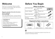
...Safety Instructions Warranty (for USA/for CANADA) Remote control unit R03/AAA batteries Required for Basic connections CD player Speaker systems Speaker cables These drawings are for illustrative purposes only and may not represent the actual product(s). 1 This guide provides step...-by-step instructions for setting up your area. 1-855-ONE-Marantz 1-855-663-6272 Call for Assistance: Monday - If you need help in solving problems, contact Marantz...
...Safety Instructions Warranty (for USA/for CANADA) Remote control unit R03/AAA batteries Required for Basic connections CD player Speaker systems Speaker cables These drawings are for illustrative purposes only and may not represent the actual product(s). 1 This guide provides step...-by-step instructions for setting up your area. 1-855-ONE-Marantz 1-855-663-6272 Call for Assistance: Monday - If you need help in solving problems, contact Marantz...

