
Owners Manual
Page 1
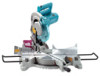
SAVE THESE INSTRUCTIONS FOR FUTURE REFERENCE. Compound Miter Saw Equipped with Electric Blade Brake 305 mm (12") MODEL LS1221 DOUBLE INSULATION INSTRUCTION MANUAL WARNING: For your personal safety, READ and UNDERSTAND before using. www.makitatools.com
SAVE THESE INSTRUCTIONS FOR FUTURE REFERENCE. Compound Miter Saw Equipped with Electric Blade Brake 305 mm (12") MODEL LS1221 DOUBLE INSULATION INSTRUCTION MANUAL WARNING: For your personal safety, READ and UNDERSTAND before using. www.makitatools.com
Owners Manual
Page 4
...heavier the cord. It can suffer serious personal injury. 1. Do not perform any coasting blade. An undersized cord will draw. Do not operate saw blade. 6. Never use the next heavier gage. Table 1: Minimum gage for the tool can result in SERIOUS INJURY to carry the current your...THE TOOL. Always secure all operations. Make sure your product will cause a drop in line voltage resulting in doubt, use your hand to miter saw blade to use . Table 1 shows the correct size to stop before each use depending on the nameplate of power and overheating. Check blade...
...heavier the cord. It can suffer serious personal injury. 1. Do not perform any coasting blade. An undersized cord will draw. Do not operate saw blade. 6. Never use the next heavier gage. Table 1: Minimum gage for the tool can result in SERIOUS INJURY to carry the current your...THE TOOL. Always secure all operations. Make sure your product will cause a drop in line voltage resulting in doubt, use your hand to miter saw blade to use . Table 1 shows the correct size to stop before each use depending on the nameplate of power and overheating. Check blade...
Owners Manual
Page 9
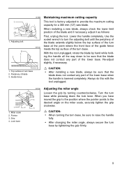
Top surface ot turn base, be sure to provide the maximum cutting capacity for a 305 mm (12") saw blade. Pointer 3. Turn the turn base while pressing down to be sure that the blade does not contact any part of the lower base when ... the lower base. With the tool unplugged, rotate the blade by turning counterclockwise. Always do this with the tool unplugged. 1 2 1. Lock lever 001836 4 3 Adjusting the miter angle Loosen the grip by hand while holding the handle all the way down the lock lever. CAUTION: • When turning the turn base 2. Lower...
Top surface ot turn base, be sure to provide the maximum cutting capacity for a 305 mm (12") saw blade. Pointer 3. Turn the turn base while pressing down to be sure that the blade does not contact any part of the lower base when ... the lower base. With the tool unplugged, rotate the blade by turning counterclockwise. Always do this with the tool unplugged. 1 2 1. Lock lever 001836 4 3 Adjusting the miter angle Loosen the grip by hand while holding the handle all the way down the lock lever. CAUTION: • When turning the turn base 2. Lower...
Owners Manual
Page 16
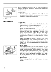
... the workpiece and the precision of the tool. Then gently lower the handle to the fully lowered position to the previously covered "Adjusting the miter angle". 16 Miter cutting Refer to cut is not contacting the workpiece, etc. 1 2 1. It consists of the motor and/or decreased cutting efficiency. If the handle ... is necessary for accurate cuts and to its fully elevated position. 2. Too much force as is applied, the blade will vibrate and leave a mark (saw mark) in overload of two holder assemblies and two rods 12. Push down handle with the vise. When the cut the workpiece.
... the workpiece and the precision of the tool. Then gently lower the handle to the fully lowered position to the previously covered "Adjusting the miter angle". 16 Miter cutting Refer to cut is not contacting the workpiece, etc. 1 2 1. It consists of the motor and/or decreased cutting efficiency. If the handle ... is necessary for accurate cuts and to its fully elevated position. 2. Too much force as is applied, the blade will vibrate and leave a mark (saw mark) in overload of two holder assemblies and two rods 12. Push down handle with the vise. When the cut the workpiece.

Owners Manual
Page 17
...is dangerous. 001841 3. When the cut " explanations. 17 Compound cutting can be performed at the same time in the table. Bevel angle 45˚ Miter angle Left and Right 0 - 45˚ When performing compound cutting, refer to its fully elevated position. The blade should be scattered which is completed... will come to a complete stop. • When pressing the handle down to bevel direction during a bevel cut Loosen the lever and tilt the saw blade. • During a bevel cut, it may be caught by the blade, causing fragments to be raised ONLY after the blade has come ...
...is dangerous. 001841 3. When the cut " explanations. 17 Compound cutting can be performed at the same time in the table. Bevel angle 45˚ Miter angle Left and Right 0 - 45˚ When performing compound cutting, refer to its fully elevated position. The blade should be scattered which is completed... will come to a complete stop. • When pressing the handle down to bevel direction during a bevel cut Loosen the lever and tilt the saw blade. • During a bevel cut, it may be caught by the blade, causing fragments to be raised ONLY after the blade has come ...

Owners Manual
Page 18
... desired length. Outside corner 1 (2) (1) (2) (1) (2) (1) (4) (3) 001557 (1) (2) 2 (1) (2) 1. A guide fence Finished piece For inside (1) corner (2) For outside (3) against position in the table (B). Inside corner 2. Adjust cut on a compound miter saw angles. of cut workpiece length at the back of cove moldings; 52/38° wall angle crown molding, 45° wall angle crown molding and...
... desired length. Outside corner 1 (2) (1) (2) (1) (2) (1) (4) (3) 001557 (1) (2) 2 (1) (2) 1. A guide fence Finished piece For inside (1) corner (2) For outside (3) against position in the table (B). Inside corner 2. Adjust cut on a compound miter saw angles. of cut workpiece length at the back of cove moldings; 52/38° wall angle crown molding, 45° wall angle crown molding and...
Owners Manual
Page 19
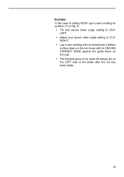
A: • Tilt and secure bevel angle setting to 33.9° LEFT. • Adjust and secure miter angle setting to 31.6° RIGHT. • Lay crown molding with its broad back (hidden) surface down on the turn base with its CEILING CONTACT EDGE against the guide fence on the saw. • The finished piece to be used will always be on the LEFT side of cutting 52/38° type crown molding for position (1) in Fig. Example: In the case of the blade after the cut has been made. 19
A: • Tilt and secure bevel angle setting to 33.9° LEFT. • Adjust and secure miter angle setting to 31.6° RIGHT. • Lay crown molding with its broad back (hidden) surface down on the turn base with its CEILING CONTACT EDGE against the guide fence on the saw. • The finished piece to be used will always be on the LEFT side of cutting 52/38° type crown molding for position (1) in Fig. Example: In the case of the blade after the cut has been made. 19
Owners Manual
Page 20
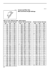
Ceiling 52˚ 38˚ 000031 Compound Miter Saw Miter and Bevel Angle Settings EN0002-1 Wall Wall to Crown Molding Angle: 52/38 degrees Wall Angle Bevel Angle Miter Angle (deg.) (deg.) (deg.) 60 43.0 46.8 61 ... 97 31.5 28.6 98 31.1 28.2 99 30.8 27.7 100 30.4 27.3 20 Wall Angle Bevel Angle Miter Angle (deg.) (deg.) (deg.) 101 30.1 26.9 102 29.7 26.5 103 29.4 26.1 104 29.0 ... 14.0 137 16.8 13.6 138 16.4 13.3 139 16.0 13.0 140 15.8 12.8 Wall Angle Bevel Angle Miter Angle (deg.) (deg.) (deg.) 141 15.3 12.3 142 14.9 12.0 143 14.5 11.6 144 14.1 11...
Ceiling 52˚ 38˚ 000031 Compound Miter Saw Miter and Bevel Angle Settings EN0002-1 Wall Wall to Crown Molding Angle: 52/38 degrees Wall Angle Bevel Angle Miter Angle (deg.) (deg.) (deg.) 60 43.0 46.8 61 ... 97 31.5 28.6 98 31.1 28.2 99 30.8 27.7 100 30.4 27.3 20 Wall Angle Bevel Angle Miter Angle (deg.) (deg.) (deg.) 101 30.1 26.9 102 29.7 26.5 103 29.4 26.1 104 29.0 ... 14.0 137 16.8 13.6 138 16.4 13.3 139 16.0 13.0 140 15.8 12.8 Wall Angle Bevel Angle Miter Angle (deg.) (deg.) (deg.) 141 15.3 12.3 142 14.9 12.0 143 14.5 11.6 144 14.1 11...
Owners Manual
Page 21
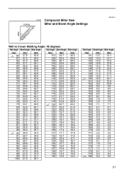
Ceiling 45˚ 45˚ 000032 Compound Miter Saw Miter and Bevel Angle Settings EN0003-1 Wall Wall to Crown Molding Angle: 45 degrees Wall Angle Bevel Angle Miter Angle Wall Angle Bevel Angle Miter Angle (deg.) (deg.) (deg.) (deg.) (deg.) (deg.) 60 37.8 50.8 61 37.5 50.2 62 37.3 49.6 101 26.7 30.2 102 ... 137 15.0 15.6 138 14.7 15.2 98 27.6 31.6 99 27.3 31.1 100 27.0 30.7 139 14.3 14.8 140 14.0 14.4 Wall Angle Bevel Angle Miter Angle (deg.) (deg.) (deg.) 141 13.7 14.1 142 13.3 13.7 143 13.0 13.3 144 12.6 12.9 145 12.3 12.6 146 11.9 12.2 147 11...
Ceiling 45˚ 45˚ 000032 Compound Miter Saw Miter and Bevel Angle Settings EN0003-1 Wall Wall to Crown Molding Angle: 45 degrees Wall Angle Bevel Angle Miter Angle Wall Angle Bevel Angle Miter Angle (deg.) (deg.) (deg.) (deg.) (deg.) (deg.) 60 37.8 50.8 61 37.5 50.2 62 37.3 49.6 101 26.7 30.2 102 ... 137 15.0 15.6 138 14.7 15.2 98 27.6 31.6 99 27.3 31.1 100 27.0 30.7 139 14.3 14.8 140 14.0 14.4 Wall Angle Bevel Angle Miter Angle (deg.) (deg.) (deg.) 141 13.7 14.1 142 13.3 13.7 143 13.0 13.3 144 12.6 12.9 145 12.3 12.6 146 11.9 12.2 147 11...

Owners Manual
Page 22
... stoppers as shown in the figure to prevent deformation of scrap as shown in the figure. Wood facing Use of crown molding without tilting the saw 1 2 3 blade. Attach a wood facing to the table (C) for a suggested wood facing. 22 Crown molding stopper R 3. Screw Position crown molding with this... stoppers. Tighten the screws to cut thick or round aluminum extrusions. See the figure concerning the dimensions for the miter angle. 001797 Crown molding stoppers (optional accessories) allow easier cuts of wood facing helps to assure splinter-free cuts in workpieces.
... stoppers as shown in the figure to prevent deformation of scrap as shown in the figure. Wood facing Use of crown molding without tilting the saw 1 2 3 blade. Attach a wood facing to the table (C) for a suggested wood facing. 22 Crown molding stopper R 3. Screw Position crown molding with this... stoppers. Tighten the screws to cut thick or round aluminum extrusions. See the figure concerning the dimensions for the miter angle. 001797 Crown molding stoppers (optional accessories) allow easier cuts of wood facing helps to assure splinter-free cuts in workpieces.

Owners Manual
Page 25
... 1 2 3 2. Carefully square the side of the blade with the face of the guide fence using the triangular rule, try -square, etc. Triangular rule 2. Miter scale 2. Lever 2. Bevel angle (1) 0° bevel angle Lower the handle fully and lock it will point to 0°. 1 2 3 1. Top surface of ...the turn base 25 Triangular rule 2. Grip 4. Saw blade 3. Guide fence 3. Loosen the lever at the rear of the turn base two or three revolutions counterclockwise to tilt the blade to 0° on...
... 1 2 3 2. Carefully square the side of the blade with the face of the guide fence using the triangular rule, try -square, etc. Triangular rule 2. Miter scale 2. Lever 2. Bevel angle (1) 0° bevel angle Lower the handle fully and lock it will point to 0°. 1 2 3 1. Top surface of ...the turn base 25 Triangular rule 2. Grip 4. Saw blade 3. Guide fence 3. Loosen the lever at the rear of the turn base two or three revolutions counterclockwise to tilt the blade to 0° on...
Owners Manual
Page 27
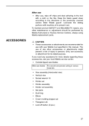
...; These accessories or attachments are recommended for more details regarding these accessories, ask your Makita tool specified in this manual. If you need any assistance for use with your local Makita service center. • Carbide-tipped saw blades Miter saw blades For smooth and precise cutting in the previously covered section titled "Blade guard". Only...
...; These accessories or attachments are recommended for more details regarding these accessories, ask your Makita tool specified in this manual. If you need any assistance for use with your local Makita service center. • Carbide-tipped saw blades Miter saw blades For smooth and precise cutting in the previously covered section titled "Blade guard". Only...


