
Owners Manual
Page 2
... mm (*Right) (1-3/4" x 5-1/2") No load speed (RPM 4,000/min. REMOVE ADJUSTING KEYS AND WRENCHES. SPECIFICATIONS Blade diameter 305 mm (12") Hole diameter 25.4 mm (1") Max. Miter angle Left 48°, Right 48° Max. For Your Own Safety Read Instruction Manual Before Operating Tool Save it on. 4. Bevel angle : ...Left 45° Max. KNOW YOUR POWER TOOL. Form habit of checking to see that keys and adjusting wrenches are removed from country to it...
... mm (*Right) (1-3/4" x 5-1/2") No load speed (RPM 4,000/min. REMOVE ADJUSTING KEYS AND WRENCHES. SPECIFICATIONS Blade diameter 305 mm (12") Hole diameter 25.4 mm (1") Max. Miter angle Left 48°, Right 48° Max. For Your Own Safety Read Instruction Manual Before Operating Tool Save it on. 4. Bevel angle : ...Left 45° Max. KNOW YOUR POWER TOOL. Form habit of checking to see that keys and adjusting wrenches are removed from country to it...

Owners Manual
Page 3
... switches, or by removing starter keys. 8. It will fit in a polarized outlet only one blade is dusty. USE RIGHT TOOL. ALWAYS USE SAFETY GLASSES. DISCONNECT TOOLS before plugging in presence of the blade or cutter only. 21. REDUCE THE RISK OF UNINTENTIONAL STARTING. Consult the owner's manual for best and safest performance. The use tool in . 17. Before further use only identical replacement parts. 23. Feed work area. 7. TURN POWER OFF...
... switches, or by removing starter keys. 8. It will fit in a polarized outlet only one blade is dusty. USE RIGHT TOOL. ALWAYS USE SAFETY GLASSES. DISCONNECT TOOLS before plugging in presence of the blade or cutter only. 21. REDUCE THE RISK OF UNINTENTIONAL STARTING. Consult the owner's manual for best and safest performance. The use tool in . 17. Before further use only identical replacement parts. 23. Feed work area. 7. TURN POWER OFF...

Owners Manual
Page 4
... number, the heavier the cord. Check blade guard for the tool can result in doubt, DO NOT PLUG IN THE TOOL. The workpiece must be secured firmly 4 against the turn base and guide fence with a vise during all moving workpiece or changing settings. 7. as well as that specified for proper closing before moving portions before changing blade or servicing. 8. USE PROPER EXTENSION CORD. Table 1 shows the correct size to use...
... number, the heavier the cord. Check blade guard for the tool can result in doubt, DO NOT PLUG IN THE TOOL. The workpiece must be secured firmly 4 against the turn base and guide fence with a vise during all moving workpiece or changing settings. 7. as well as that specified for proper closing before moving portions before changing blade or servicing. 8. USE PROPER EXTENSION CORD. Table 1 shows the correct size to use...

Owners Manual
Page 5
... lock is released before operation. Hold the handle firmly. Watch for and remove all times, especially during start-up and stopping. 19. Stop operation immediately if you notice anything abnormal. 23. Never yank cord to clean blade. 11. Gum and wood pitch hardened on . 17. Keep blade clean by first removing it from the workpiece before the switch is called cross-armed cutting and exposes user...
... lock is released before operation. Hold the handle firmly. Watch for and remove all times, especially during start-up and stopping. 19. Stop operation immediately if you notice anything abnormal. 23. Never yank cord to clean blade. 11. Gum and wood pitch hardened on . 17. Keep blade clean by first removing it from the workpiece before the switch is called cross-armed cutting and exposes user...

Owners Manual
Page 7
... irregular operation of the blade guard should be corrected immediately. AGED, FAULTY OR REMOVED. NEVER DEFEAT OR REMOVE THE BLADE GUARD OR THE SPRING WHICH ATTACHES TO THE GUARD. 1 In the interest of guard. INSTALLATION 001794 Bench mounting When the tool is shipped, the handle is locked in the lowered position by lowering the handle slightly and pulling the stopper pin. 1 1. Release the stopper pin by the stopper pin. DOING...
... irregular operation of the blade guard should be corrected immediately. AGED, FAULTY OR REMOVED. NEVER DEFEAT OR REMOVE THE BLADE GUARD OR THE SPRING WHICH ATTACHES TO THE GUARD. 1 In the interest of guard. INSTALLATION 001794 Bench mounting When the tool is shipped, the handle is locked in the lowered position by lowering the handle slightly and pulling the stopper pin. 1 1. Release the stopper pin by the stopper pin. DOING...

Owners Manual
Page 8
... the tool. Left bevel cut . Lower the handle fully and push in the lowered position. Blade guard 1 1. Do not remove spring holding the center cover. Adjust the kerf boards so that the kerf boards can be easily moved by turning it in the turn base to loosen the hex bolt holding blade guard. After adjusting the kerf boards, release the stopper pin and raise the handle. tact a Makita service center...
... the tool. Left bevel cut . Lower the handle fully and push in the lowered position. Blade guard 1 1. Do not remove spring holding the center cover. Adjust the kerf boards so that the kerf boards can be easily moved by turning it in the turn base to loosen the hex bolt holding blade guard. After adjusting the kerf boards, release the stopper pin and raise the handle. tact a Makita service center...
Owners Manual
Page 9
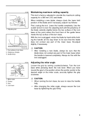
... face of the guide fence 001540 meets the top surface of blade 3. Pointer 3. Periphery of the turn base. Lock lever 001836 4 3 Adjusting the miter angle Loosen the grip by tightening the grip firmly. 9 Adjusting bolt 2 1 001835 Maintaining maximum cutting capacity This tool is lowered completely. Miter scale 2. CAUTION: • When turning the turn base, be sure to raise the handle fully. • After changing the miter angle, always secure the turn base while pressing...
... face of the guide fence 001540 meets the top surface of blade 3. Pointer 3. Periphery of the turn base. Lock lever 001836 4 3 Adjusting the miter angle Loosen the grip by tightening the grip firmly. 9 Adjusting bolt 2 1 001835 Maintaining maximum cutting capacity This tool is lowered completely. Miter scale 2. CAUTION: • When turning the turn base, be sure to raise the handle fully. • After changing the miter angle, always secure the turn base while pressing...

Owners Manual
Page 10
... not using the tool, remove the lock-off button is HIGHLY DANGEROUS and must be sure to the desired angle on the bevel scale. Push the handle to the left to tilt the saw blade, be sure to raise the handle fully. • After changing the bevel angle, always secure the arm by tightening the lever clockwise. • When changing bevel angles, be repaired before further usage. 10 Lock-off button. Switch trigger 001833 1 2 Switch...
... not using the tool, remove the lock-off button is HIGHLY DANGEROUS and must be sure to the desired angle on the bevel scale. Push the handle to the left to tilt the saw blade, be sure to raise the handle fully. • After changing the bevel angle, always secure the arm by tightening the lever clockwise. • When changing bevel angles, be repaired before further usage. 10 Lock-off button. Switch trigger 001833 1 2 Switch...

Owners Manual
Page 11
... that the tool is equipped with a lock-off button which prevents the tool from unintended starting. Return tool to a Makita service center for blade guard. The blade brake system is equipped with an electric blade brake. Failure to the wrench holder. When using the socket wrench, return it to do so may result in the figure. Wrench holder • For your safety, this tool is not a substitute for proper repairs BEFORE further...
... that the tool is equipped with a lock-off button which prevents the tool from unintended starting. Return tool to a Makita service center for blade guard. The blade brake system is equipped with an electric blade brake. Failure to the wrench holder. When using the socket wrench, return it to do so may result in the figure. Wrench holder • For your safety, this tool is not a substitute for proper repairs BEFORE further...
Owners Manual
Page 13
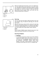
... sure shaft lock has released spindle before making cut. 001831 Dust bag The use of 3 its original position. Also, after a cutting operation, DO NOT raise the blade until the blade has come to make sure that the blade guard moves properly. Fastener 001785 43 Return the blade guard and center cover to its contents, tapping it onto the dust nozzle. Lower the handle to a complete stop. 13...
... sure shaft lock has released spindle before making cut. 001831 Dust bag The use of 3 its original position. Also, after a cutting operation, DO NOT raise the blade until the blade has come to make sure that the blade guard moves properly. Fastener 001785 43 Return the blade guard and center cover to its contents, tapping it onto the dust nozzle. Lower the handle to a complete stop. 13...

Owners Manual
Page 14
Turn base 1 001549 2 CAUTION: • When cutting long workpieces, use supports that no part of the tool contacts the vise when lowering the handle all the way. It should be installed in the guide fence or the holder assembly and tighten the screw to sag. Vise rod 3. Otherwise, it will contact the blade or a part of the tool, causing possible serious injury to secure the vise arm contacts the...
Turn base 1 001549 2 CAUTION: • When cutting long workpieces, use supports that no part of the tool contacts the vise when lowering the handle all the way. It should be installed in the guide fence or the holder assembly and tighten the screw to sag. Vise rod 3. Otherwise, it will contact the blade or a part of the tool, causing possible serious injury to secure the vise arm contacts the...

Owners Manual
Page 15
... knob 1 2 1. Holder assembly Press the workpiece flat against the turn base is to the blade or cause the loss of workpiece which can result in PERSONAL INJURY. 001809 Holders and holder assembly (optional accessories) The holders and the holder assembly can be installed in and out. When performing 15° or greater miter cuts, install the horizontal vise on the side opposite the direction in which the turn base and guide fence...
... knob 1 2 1. Holder assembly Press the workpiece flat against the turn base is to the blade or cause the loss of workpiece which can result in PERSONAL INJURY. 001809 Holders and holder assembly (optional accessories) The holders and the holder assembly can be installed in and out. When performing 15° or greater miter cuts, install the horizontal vise on the side opposite the direction in which the turn base and guide fence...
Owners Manual
Page 16
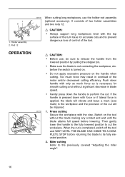
... is completed, switch off the tool and WAIT UNTIL THE BLADE HAS COME TO A COMPLETE STOP before lowering. OPERATION CAUTION: • Before use the holder-rod assembly (optional accessory). 1 2 1. When the cut is necessary for accurate cuts and to perform the cut the workpiece. Then gently lower the handle to the fully lowered position to the previously covered "Adjusting the miter angle". 16 Miter cutting Refer to cut . Rod...
... is completed, switch off the tool and WAIT UNTIL THE BLADE HAS COME TO A COMPLETE STOP before lowering. OPERATION CAUTION: • Before use the holder-rod assembly (optional accessory). 1 2 1. When the cut is necessary for accurate cuts and to perform the cut the workpiece. Then gently lower the handle to the fully lowered position to the previously covered "Adjusting the miter angle". 16 Miter cutting Refer to cut . Rod...

Owners Manual
Page 17
... whereby the piece cut off will be scattered which a miter angle is completed, switch off the tool and WAIT UNTIL THE BLADE HAS COME TO A COMPLETE STOP before returning the blade to the fully lowered position while applying pressure in parallel with a vise. If the pressure is dangerous. Be sure to retighten the lever firmly to the previously covered "Adjusting the bevel angle"). Compound cutting Compound cutting is the...
... whereby the piece cut off will be scattered which a miter angle is completed, switch off the tool and WAIT UNTIL THE BLADE HAS COME TO A COMPLETE STOP before returning the blade to the fully lowered position while applying pressure in parallel with a vise. If the pressure is dangerous. Be sure to retighten the lever firmly to the previously covered "Adjusting the bevel angle"). Compound cutting Compound cutting is the...

Owners Manual
Page 18
... be cut wall contact edge to desired length. Outside corner 1 (2) (1) (2) (1) (2) (1) (4) (3) 001557 (1) (2) 2 (1) (2) 1. A guide fence Finished piece For inside (1) corner (2) For outside (3) against position in Fig. Finished piece will be of blade. 18 Outside corner Measuring Measure the wall length and adjust workpiece on a compound miter saw angles. Always make sure that cut . Table (A) Molding Bevel angle position in the table (B). A) and "Outside" 90° corners ((3) and (4) in Fig. Adjust cut length...
... be cut wall contact edge to desired length. Outside corner 1 (2) (1) (2) (1) (2) (1) (4) (3) 001557 (1) (2) 2 (1) (2) 1. A guide fence Finished piece For inside (1) corner (2) For outside (3) against position in Fig. Finished piece will be of blade. 18 Outside corner Measuring Measure the wall length and adjust workpiece on a compound miter saw angles. Always make sure that cut . Table (A) Molding Bevel angle position in the table (B). A) and "Outside" 90° corners ((3) and (4) in Fig. Adjust cut length...

Owners Manual
Page 22
... block 001844 1 2 3 4 5 6. Aluminum extrusion 5. Crown molding stopper R 3. Guide fence 2. Spacer block 3. A (1) (2) (3) (4) Table (C) Miter angle Finished piece Right 45˚ Left 45˚ Right 45˚ Save the right side of blade Save the left side of blade Save the right side of blade Save the left side of crown molding without tilting the saw 1 2 3 blade. 001797 Crown molding stoppers (optional accessories) allow easier cuts of blade 1. Cutting aluminum extrusion When securing...
... block 001844 1 2 3 4 5 6. Aluminum extrusion 5. Crown molding stopper R 3. Guide fence 2. Spacer block 3. A (1) (2) (3) (4) Table (C) Miter angle Finished piece Right 45˚ Left 45˚ Right 45˚ Save the right side of blade Save the left side of blade Save the right side of blade Save the left side of crown molding without tilting the saw 1 2 3 blade. 001797 Crown molding stoppers (optional accessories) allow easier cuts of blade 1. Cutting aluminum extrusion When securing...
Owners Manual
Page 23
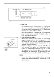
... (11 - 5/8") to 440 mm (17 x 1/4"), use of the holder-rod assembly (optional accessory) allows cutting repetitive lengths up to the guide fence. Install the set plate out of the workpiece. Over 10mm (3/8") Over 580mm (22-3/4") 001845 1 1. Holder 3. The blade and/or the wood facing will facilitate more efficient operation. Then secure the set plate (optional accessory) will be installed so that the screw heads are below the surface of...
... (11 - 5/8") to 440 mm (17 x 1/4"), use of the holder-rod assembly (optional accessory) allows cutting repetitive lengths up to the guide fence. Install the set plate out of the workpiece. Over 10mm (3/8") Over 580mm (22-3/4") 001845 1 1. Holder 3. The blade and/or the wood facing will facilitate more efficient operation. Then secure the set plate (optional accessory) will be installed so that the screw heads are below the surface of...

Owners Manual
Page 24
... pin is switched off and unplugged before attempting to 0° on the miter scale. MAINTENANCE CAUTION: • Always be sure that the blade is not aligned properly, perform the following: 001849 1. Then turn the turn base slightly clockwise and counterclockwise to 0°.) 1 Loosen the hex bolts securing the guide fence using the socket wrench. 24 Secure the blade at right miter angle fully. If you remove...
... pin is switched off and unplugged before attempting to 0° on the miter scale. MAINTENANCE CAUTION: • Always be sure that the blade is not aligned properly, perform the following: 001849 1. Then turn the turn base slightly clockwise and counterclockwise to 0°.) 1 Loosen the hex bolts securing the guide fence using the socket wrench. 24 Secure the blade at right miter angle fully. If you remove...

Owners Manual
Page 26
... the carbon brushes regularly. Keep the carbon brushes clean and free to slip in brushes by running and electric brake operation when releasing the switch trigger. Bevel scale 2. To adjust left 45° bevel angle, loosen the lever and tilt the blade to the limit mark. Limit mark 1. Both carbon brushes should be replaced at the same time. After replacing brushes, plug in the tool and break in the holders. Use only identical carbon brushes. 1 001853 1 2 Use a screwdriver to...
... the carbon brushes regularly. Keep the carbon brushes clean and free to slip in brushes by running and electric brake operation when releasing the switch trigger. Bevel scale 2. To adjust left 45° bevel angle, loosen the lever and tilt the blade to the limit mark. Limit mark 1. Both carbon brushes should be replaced at the same time. After replacing brushes, plug in the tool and break in the holders. Use only identical carbon brushes. 1 001853 1 2 Use a screwdriver to...
Owners Manual
Page 27
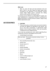
... local Makita service center. • Carbide-tipped saw blades Miter saw blades For smooth and precise cutting in various materials. • Vise assembly (Horizontal vise) • Vertical vise • Socket wrench 13 • Holder set • Holder assembly • Holder rod assembly • Set plate • Dust bag • Elbow • Crown molding stopper set • Triangular rule • Lock-off chips and dust adhering to prevent rust. ACCESSORIES After use • After use, wipe off button (2 pcs...
... local Makita service center. • Carbide-tipped saw blades Miter saw blades For smooth and precise cutting in various materials. • Vise assembly (Horizontal vise) • Vertical vise • Socket wrench 13 • Holder set • Holder assembly • Holder rod assembly • Set plate • Dust bag • Elbow • Crown molding stopper set • Triangular rule • Lock-off chips and dust adhering to prevent rust. ACCESSORIES After use • After use, wipe off button (2 pcs...


