
Owners Manual
Page 2
... Left 48°, Right 48° Max. KEEP WORK AREA CLEAN. SPECIFICATIONS Blade diameter 305 mm (12") Hole diameter 25.4 mm (1") Max. Bevel angle : ...Left 45° Max. Read the owner's manual carefully. KEEP GUARDS IN PLACE and in working order. 2 3. KNOW YOUR POWER... TOOL. Form habit of checking to country. Cluttered areas and benches invite accidents. Cutting capacities (H x W) Bevel angle Miter angle 0° 45° (left and right) 98 mm x 153 mm 98 mm x 107 mm 0° (3-7/8" x 6") 63.5 mm x 203 ...
... Left 48°, Right 48° Max. KEEP WORK AREA CLEAN. SPECIFICATIONS Blade diameter 305 mm (12") Hole diameter 25.4 mm (1") Max. Bevel angle : ...Left 45° Max. Read the owner's manual carefully. KEEP GUARDS IN PLACE and in working order. 2 3. KNOW YOUR POWER... TOOL. Form habit of checking to country. Cluttered areas and benches invite accidents. Cutting capacities (H x W) Bevel angle Miter angle 0° 45° (left and right) 98 mm x 153 mm 98 mm x 107 mm 0° (3-7/8" x 6") 63.5 mm x 203 ...

Owners Manual
Page 8
...screws (do not tighten firmly). Loosen all the screws (2 each on the exit side of the blade teeth. Tighten all the screws securely. Left bevel cut If the see-through age or UV light exposure, con- Do not use solvents or any petroleum-based cleaners on the plastic guard. 001782...saw blade does not contact the kerf boards. Adjust the kerf boards so that the kerf boards just contact the sides of a cut. tact a Makita service center for a new guard. Re-tighten them only to it counterclockwise and raise the blade guard and center cover. After adjusting the kerf boards...
...screws (do not tighten firmly). Loosen all the screws (2 each on the exit side of the blade teeth. Tighten all the screws securely. Left bevel cut If the see-through age or UV light exposure, con- Do not use solvents or any petroleum-based cleaners on the plastic guard. 001782...saw blade does not contact the kerf boards. Adjust the kerf boards so that the kerf boards just contact the sides of a cut. tact a Makita service center for a new guard. Re-tighten them only to it counterclockwise and raise the blade guard and center cover. After adjusting the kerf boards...

Owners Manual
Page 10
...the switch trigger. Any tool with an inoperative switch is provided. Lever 1. Lever 001837 1 001838 1 2 3 Adjusting the bevel angle To adjust the bevel angle, loosen the lever at the rear of the tool counterclockwise. Lock-off button. This prevents unauthorized operation. • Do...tool without pressing in the "Positioning kerf boards" section. 1. Then tighten the lever clockwise firmly to stop. This can cause switch breakage. Bevel scale 3. Switch trigger 001833 1 2 Switch action CAUTION: • Before plugging in the tool, always check to see that the switch trigger...
...the switch trigger. Any tool with an inoperative switch is provided. Lever 1. Lever 001837 1 001838 1 2 3 Adjusting the bevel angle To adjust the bevel angle, loosen the lever at the rear of the tool counterclockwise. Lock-off button. This prevents unauthorized operation. • Do...tool without pressing in the "Positioning kerf boards" section. 1. Then tighten the lever clockwise firmly to stop. This can cause switch breakage. Bevel scale 3. Switch trigger 001833 1 2 Switch action CAUTION: • Before plugging in the tool, always check to see that the switch trigger...

Owners Manual
Page 14
... the screw. Sub-fence 1 2 3 4 5 1. Holder 5. Screw 14 001843 CAUTION: • When performing left position as shown in the figure. If the screw to the left bevel cuts, flip the fence over its entire length to secure the workpiece.
... the screw. Sub-fence 1 2 3 4 5 1. Holder 5. Screw 14 001843 CAUTION: • When performing left position as shown in the figure. If the screw to the left bevel cuts, flip the fence over its entire length to secure the workpiece.

Owners Manual
Page 17
...piece may create a condition whereby the piece cut . Secure the workpiece with the blade. Keep hands out of path of saw blade to set the bevel angle (Refer to the fully lowered position while applying pressure in which a miter angle is completed, switch off will be impaired. • Always set... the sub-fence to the left position when performing left bevel cuts. 4. If the blade is raised while the blade is dangerous. Compound cutting can be caught by the blade, causing fragments to its fully ...
...piece may create a condition whereby the piece cut . Secure the workpiece with the blade. Keep hands out of path of saw blade to set the bevel angle (Refer to the fully lowered position while applying pressure in which a miter angle is completed, switch off will be impaired. • Always set... the sub-fence to the left position when performing left bevel cuts. 4. If the blade is raised while the blade is dangerous. Compound cutting can be caught by the blade, causing fragments to its fully ...

Owners Manual
Page 18
A). (1) (2) (3) (4) Fig.A 1 2 1. Table (A) Molding Bevel angle position in Fig. be on the Left side (2) Wall contact edge should Finished piece will corner (4) Ceiling contact edge should be be of cove ...; 45∞ There are made to fit "Inside" 90° corners ((1) and (2) in the table (B). Inside corner 2. When cutting crown and cove moldings, set the bevel angle and miter angle as wall length. A 52/38˚ type 45˚ type For inside corner (1) Ceiling contact edge should be on the top...
A). (1) (2) (3) (4) Fig.A 1 2 1. Table (A) Molding Bevel angle position in Fig. be on the Left side (2) Wall contact edge should Finished piece will corner (4) Ceiling contact edge should be be of cove ...; 45∞ There are made to fit "Inside" 90° corners ((1) and (2) in the table (B). Inside corner 2. When cutting crown and cove moldings, set the bevel angle and miter angle as wall length. A 52/38˚ type 45˚ type For inside corner (1) Ceiling contact edge should be on the top...
Owners Manual
Page 19
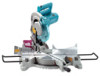
Example: In the case of the blade after the cut has been made. 19 A: • Tilt and secure bevel angle setting to 33.9° LEFT. • Adjust and secure miter angle setting to 31.6° RIGHT. • Lay crown molding with its broad back (hidden) surface down on the turn base with its CEILING CONTACT EDGE against the guide fence on the saw. • The finished piece to be used will always be on the LEFT side of cutting 52/38° type crown molding for position (1) in Fig.
Example: In the case of the blade after the cut has been made. 19 A: • Tilt and secure bevel angle setting to 33.9° LEFT. • Adjust and secure miter angle setting to 31.6° RIGHT. • Lay crown molding with its broad back (hidden) surface down on the turn base with its CEILING CONTACT EDGE against the guide fence on the saw. • The finished piece to be used will always be on the LEFT side of cutting 52/38° type crown molding for position (1) in Fig.
Owners Manual
Page 20
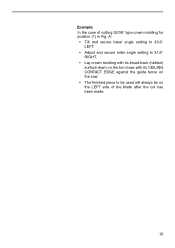
... Settings EN0002-1 Wall Wall to Crown Molding Angle: 52/38 degrees Wall Angle Bevel Angle Miter Angle (deg.) (deg.) (deg.) 60 43.0 46.8 61 42.8 46.3 62 ...32.2 29.4 96 31.8 29.0 97 31.5 28.6 98 31.1 28.2 99 30.8 27.7 100 30.4 27.3 20 Wall Angle Bevel Angle Miter Angle (deg.) (deg.) (deg.) 101 30.1 26.9 102 29.7 26.5 103 29.4 26.1 104 29.0 25.7 ...135 17.6 14.3 136 17.2 14.0 137 16.8 13.6 138 16.4 13.3 139 16.0 13.0 140 15.8 12.8 Wall Angle Bevel Angle Miter Angle (deg.) (deg.) (deg.) 141 15.3 12.3 142 14.9 12.0 143 14.5 11.6 144 14.1 11.3 ...
... Settings EN0002-1 Wall Wall to Crown Molding Angle: 52/38 degrees Wall Angle Bevel Angle Miter Angle (deg.) (deg.) (deg.) 60 43.0 46.8 61 42.8 46.3 62 ...32.2 29.4 96 31.8 29.0 97 31.5 28.6 98 31.1 28.2 99 30.8 27.7 100 30.4 27.3 20 Wall Angle Bevel Angle Miter Angle (deg.) (deg.) (deg.) 101 30.1 26.9 102 29.7 26.5 103 29.4 26.1 104 29.0 25.7 ...135 17.6 14.3 136 17.2 14.0 137 16.8 13.6 138 16.4 13.3 139 16.0 13.0 140 15.8 12.8 Wall Angle Bevel Angle Miter Angle (deg.) (deg.) (deg.) 141 15.3 12.3 142 14.9 12.0 143 14.5 11.6 144 14.1 11.3 ...
Owners Manual
Page 21
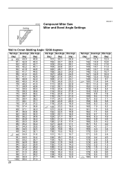
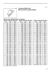
Ceiling 45˚ 45˚ 000032 Compound Miter Saw Miter and Bevel Angle Settings EN0003-1 Wall Wall to Crown Molding Angle: 45 degrees Wall Angle Bevel Angle Miter Angle Wall Angle Bevel Angle Miter Angle (deg.) (deg.) (deg.) (deg.) (deg.) (deg.) 60 37.8 50.8 61 37.5 50.2 62 37.3 49.6 101 26.7 30.2... 15.4 15.9 137 15.0 15.6 138 14.7 15.2 98 27.6 31.6 99 27.3 31.1 100 27.0 30.7 139 14.3 14.8 140 14.0 14.4 Wall Angle Bevel Angle Miter Angle (deg.) (deg.) (deg.) 141 13.7 14.1 142 13.3 13.7 143 13.0 13.3 144 12.6 12.9 145 12.3 12.6 146 11.9 12.2 ...
Ceiling 45˚ 45˚ 000032 Compound Miter Saw Miter and Bevel Angle Settings EN0003-1 Wall Wall to Crown Molding Angle: 45 degrees Wall Angle Bevel Angle Miter Angle Wall Angle Bevel Angle Miter Angle (deg.) (deg.) (deg.) (deg.) (deg.) (deg.) 60 37.8 50.8 61 37.5 50.2 62 37.3 49.6 101 26.7 30.2... 15.4 15.9 137 15.0 15.6 138 14.7 15.2 98 27.6 31.6 99 27.3 31.1 100 27.0 30.7 139 14.3 14.8 140 14.0 14.4 Wall Angle Bevel Angle Miter Angle (deg.) (deg.) (deg.) 141 13.7 14.1 142 13.3 13.7 143 13.0 13.3 144 12.6 12.9 145 12.3 12.6 146 11.9 12.2 ...

Owners Manual
Page 24
... the tool more easily. 001794 Carrying tool Make sure that the tool is not aligned properly, perform the following: 001849 1. Secure the blade at 0° bevel angle and the turn base slightly clockwise and counterclockwise to 0° on the miter scale. Turn the turn base so that the pointer points to...
... the tool more easily. 001794 Carrying tool Make sure that the tool is not aligned properly, perform the following: 001849 1. Secure the blade at 0° bevel angle and the turn base slightly clockwise and counterclockwise to 0° on the miter scale. Turn the turn base so that the pointer points to...

Owners Manual
Page 25
001848 Lower the handle fully and lock it in the lowered position by pushing in the stopper pin. Turn base 3. 0° bevel angle adjusting bolt 001819 1 2 3 2. by pushing in the order from the right side. 1. Lock lever 001850 1 2 3 1. Carefully square the side of the ...triangular rule, try -square, etc. Then securely tighten the hex bolts on the guide fence in the stopper pin. Miter scale 2. Turn the 0° bevel angle adjusting bolt on the miter scale. Saw blade 3. Grip 4. Guide fence 3. Lever 2. Loosen the lever at the rear of the turn base 25...
001848 Lower the handle fully and lock it in the lowered position by pushing in the stopper pin. Turn base 3. 0° bevel angle adjusting bolt 001819 1 2 3 2. by pushing in the order from the right side. 1. Lock lever 001850 1 2 3 1. Carefully square the side of the ...triangular rule, try -square, etc. Then securely tighten the hex bolts on the guide fence in the stopper pin. Miter scale 2. Turn the 0° bevel angle adjusting bolt on the miter scale. Saw blade 3. Grip 4. Guide fence 3. Lever 2. Loosen the lever at the rear of the turn base 25...

Owners Manual
Page 26
...;, loosen the screw which secures the pointer 2 and adjust the pointer so that it will point to 45° on the bevel scale on the arm. Make sure that the pointer on the turn base points to 0°. 3 1. Take out the worn... the holders. Pointer 3. Turn base 4. If the pointer does not point to 45°, turn the 45° bevel angle adjusting bolt on the right side of the arm until the pointer points to remove the brush holder caps. Brush holder... no load for repair. 26 If electric brake is not working well, ask your local Makita service center for about 10 minutes.
...;, loosen the screw which secures the pointer 2 and adjust the pointer so that it will point to 45° on the bevel scale on the arm. Make sure that the pointer on the turn base points to 0°. 3 1. Take out the worn... the holders. Pointer 3. Turn base 4. If the pointer does not point to 45°, turn the 45° bevel angle adjusting bolt on the right side of the arm until the pointer points to remove the brush holder caps. Brush holder... no load for repair. 26 If electric brake is not working well, ask your local Makita service center for about 10 minutes.
