
Parts Breakdown
Page 2
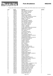
...-6 233436-0 450250-1 911128-8 450241-2 Part Name TOOL HOLDER CAP, HR3210C RING SPRING 19, HR2450F CHUCK COVER, HR3210C RING 21, HR3210C STEEL BALL 7.0, HR2400 GUIDE WASHER,HR3210C CONICAL COMP. BOLT M6X25, HM1100C BARREL CPL. BOLT M4X14, 6922NB CRANK HOUSING COVER, HR3210C TAPPING SCREW 4X14, 2012NB CRANK CAP COVER ,HR3210C TAPPING SCREW 4X18, 4323K CHANGE LEVER. SPRING 3, HR4001C LOCK...
...-6 233436-0 450250-1 911128-8 450241-2 Part Name TOOL HOLDER CAP, HR3210C RING SPRING 19, HR2450F CHUCK COVER, HR3210C RING 21, HR3210C STEEL BALL 7.0, HR2400 GUIDE WASHER,HR3210C CONICAL COMP. BOLT M6X25, HM1100C BARREL CPL. BOLT M4X14, 6922NB CRANK HOUSING COVER, HR3210C TAPPING SCREW 4X14, 2012NB CRANK CAP COVER ,HR3210C TAPPING SCREW 4X18, 4323K CHANGE LEVER. SPRING 3, HR4001C LOCK...
Technical Reference
Page 1
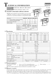
...the three models. AVT Active dynamic vibration absorber Vibration absorbing handle Quick change drill chuck (for HR3210FCT only) ..... 1 Note: The standard equipment for HR3210FCT only) HR3200C, HR3210C, HR3210FCT Description Rotary Hammer 32mm (1-1/4") CONCEPT AND MAIN APPLICATIONS PRODUCT P 1/ 24...93G (containing Bit grease 1 Depth gauge 1 Quick change drill chuck LED Job light HR3200C No No No HR3210C HR3210FCT Yes Yes No Yes No Yes Model No. Length (L) Width (W) Height (H) Dimensions: mm (") HR3200C HR3210C HR3210FCT 398 (15-5/8) 424 (16-3/4) 108 (4-1/4) 114 (4-1/2)...
...the three models. AVT Active dynamic vibration absorber Vibration absorbing handle Quick change drill chuck (for HR3210FCT only) ..... 1 Note: The standard equipment for HR3210FCT only) HR3200C, HR3210C, HR3210FCT Description Rotary Hammer 32mm (1-1/4") CONCEPT AND MAIN APPLICATIONS PRODUCT P 1/ 24...93G (containing Bit grease 1 Depth gauge 1 Quick change drill chuck LED Job light HR3200C No No No HR3210C HR3210FCT Yes Yes No Yes No Yes Model No. Length (L) Width (W) Height (H) Dimensions: mm (") HR3200C HR3210C HR3210FCT 398 (15-5/8) 424 (16-3/4) 108 (4-1/4) 114 (4-1/2)...
Technical Reference
Page 5
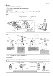
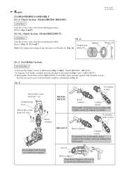
... Remove Guide washer and Conical compression spring 22-32. [3] -1A. Retaining ring S-28 Repair [3] DISASSEMBLY/ASSEMBLY [3] -1. Chuck Section (Model HR3200, HR3210C) DISASSEMBLY 1) Remove Controller and Handle section and then upright the machine as illustrated in Fig. 5. 2) Disassemble Chuck section as illustrated in Fig. 6. with 1R288 Guide washer Remove Steel ball 7 with Slotted screwdriver...
... Remove Guide washer and Conical compression spring 22-32. [3] -1A. Retaining ring S-28 Repair [3] DISASSEMBLY/ASSEMBLY [3] -1. Chuck Section (Model HR3200, HR3210C) DISASSEMBLY 1) Remove Controller and Handle section and then upright the machine as illustrated in Fig. 5. 2) Disassemble Chuck section as illustrated in Fig. 6. with 1R288 Guide washer Remove Steel ball 7 with Slotted screwdriver...
Technical Reference
Page 6
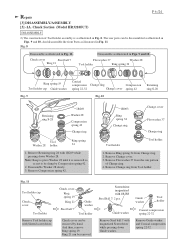
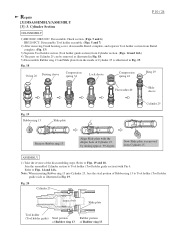
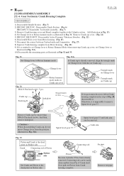
... as illustrated in Fig. 8. Note: Keep to be removed. Guide washer Remove Steel ball 7 with 1R269 while pressing down Guide washer. Chuck Section (Model HR3210FCT) DISASSEMBLY 2) The construction of Change ring. 4. Remove Retaining ring 28 with magnetized Screwdriver while pressing down Washer 28. Remove...Tool holder assembly is removed so as illustrated in Fig. 11. Remove Change ring from Change ring. 2. Disassemble Washer 28 slowly. 3. Chuck cover Steel ball 7 Ring 21 Disassemble as illustrated in Figs. 9 and 10. And then, remove Ring spring 19. Guide washer ...
... as illustrated in Fig. 8. Note: Keep to be removed. Guide washer Remove Steel ball 7 with 1R269 while pressing down Guide washer. Chuck Section (Model HR3210FCT) DISASSEMBLY 2) The construction of Change ring. 4. Remove Retaining ring 28 with magnetized Screwdriver while pressing down Washer 28. Remove...Tool holder assembly is removed so as illustrated in Fig. 11. Remove Change ring from Change ring. 2. Disassemble Washer 28 slowly. 3. Chuck cover Steel ball 7 Ring 21 Disassemble as illustrated in Figs. 9 and 10. And then, remove Ring spring 19. Guide washer ...
Technical Reference
Page 7
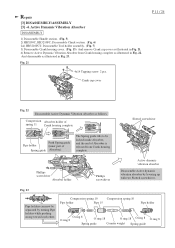
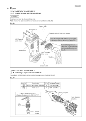
Tool Holder Section DISASSEMBLY 1) Disassemble Chuck section as illustrated in Figs. 5 and 6. (Model HR3200C, HR3210C) 1A) Separate Tool holder assembly from Barrel complete as illustrated in Figs 5 and 7. (HR3210FCT) 2) Disassemble Tool holder section (...Compression spring 42 into the groove of the disassembling procedure. Fig. 13 Tool holder section M4x16 Hex socket head bolt: 1 pc. HR3200C HR3210C Barrel complete Barrel complete Cylinder section Disassemble Tool holder section together with Cylinder section by striking Tool holder. Disassemble Crank housing cover and Barrel...
Tool Holder Section DISASSEMBLY 1) Disassemble Chuck section as illustrated in Figs. 5 and 6. (Model HR3200C, HR3210C) 1A) Separate Tool holder assembly from Barrel complete as illustrated in Figs 5 and 7. (HR3210FCT) 2) Disassemble Tool holder section (...Compression spring 42 into the groove of the disassembling procedure. Fig. 13 Tool holder section M4x16 Hex socket head bolt: 1 pc. HR3200C HR3210C Barrel complete Barrel complete Cylinder section Disassemble Tool holder section together with Cylinder section by striking Tool holder. Disassemble Crank housing cover and Barrel...
Technical Reference
Page 10
.... 19 and 18. Now Slide plate is removed from the inside of Cylinder 25 by turning approx. 90 degree. Cylinder Section P 10 / 24 DISASSEMBLY 1) HR3200C, HR3210C: Disassemble Chuck section. (Figs. 5 and 6) HR3210FCT: Disassemble Tool holder assembly. (Figs. 5 and 7) 2) After removing Crank housing cover, disassemble Barrel complete, and separate Tool holder section from...
.... 19 and 18. Now Slide plate is removed from the inside of Cylinder 25 by turning approx. 90 degree. Cylinder Section P 10 / 24 DISASSEMBLY 1) HR3200C, HR3210C: Disassemble Chuck section. (Figs. 5 and 6) HR3210FCT: Disassemble Tool holder assembly. (Figs. 5 and 7) 2) After removing Crank housing cover, disassemble Barrel complete, and separate Tool holder section from...
Technical Reference
Page 11
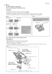
... weight Spring guide And disassemble as follows. Fig. 21 4x14 Tapping screw: 2 pcs. Active Dynamic Vibration Absorber DISASSEMBLY 1) Disassemble Handle section. (Fig. 5) 2) HR3200C, HR3210FC: Disassemble Chuck section. (Fig. 6) 2A) HR3210FCT: Disassemble Tool holder assembly. (Fig. 7) 3) Disassemble Crank housing cover. (Fig. 13) And remove Crank cap cover as illustrated in Fig. 22...
... weight Spring guide And disassemble as follows. Fig. 21 4x14 Tapping screw: 2 pcs. Active Dynamic Vibration Absorber DISASSEMBLY 1) Disassemble Handle section. (Fig. 5) 2) HR3200C, HR3210FC: Disassemble Chuck section. (Fig. 6) 2A) HR3210FCT: Disassemble Tool holder assembly. (Fig. 7) 3) Disassemble Crank housing cover. (Fig. 13) And remove Crank cap cover as illustrated in Fig. 22...
Technical Reference
Page 12
... the position in place as not to be stuck and check that the tip of Compression spring 10. [3] -5. Crank cap cover Active dymamic vibration absorber (HR3210C, HR3210FCT) Handle Section 5x20 Pan head screw: 2 pcs. Fig. 25 4x14 Tapping screw: 2 pcs. Compression Compression spring 10 spring 10 Spring guide Spring ... cover, Active dymamic vibration absorber, Handl.e section and Rear cover from Crank housing complete and Motor housing. Motor Section, Torque Limiter Section DISASSEMBLY 1) HR3200C, HR3210C: Disassemble Chuck section. (Fig. 6). Repair [3] DISASSEMBLY/ASSEMBLY [3] -4.
... the position in place as not to be stuck and check that the tip of Compression spring 10. [3] -5. Crank cap cover Active dymamic vibration absorber (HR3210C, HR3210FCT) Handle Section 5x20 Pan head screw: 2 pcs. Fig. 25 4x14 Tapping screw: 2 pcs. Compression Compression spring 10 spring 10 Spring guide Spring ... cover, Active dymamic vibration absorber, Handl.e section and Rear cover from Crank housing complete and Motor housing. Motor Section, Torque Limiter Section DISASSEMBLY 1) HR3200C, HR3210C: Disassemble Chuck section. (Fig. 6). Repair [3] DISASSEMBLY/ASSEMBLY [3] -4.
Technical Reference
Page 15
Gear Section in Crank Housing Complete P 15 / 24 DISASSEMBLY 1) Disassemble Handle Section (Fig. 5) 2) HR3200C, HR3210C: Disassemble Chuck Section (Fig. 6) HR3210FCT: Disassemble Tool holder assembly. (Fig. 7) 3) Remove Crank housing cover and Barrel complete together with that on Striker...Rotary Hammer Mode when removing Crank cap cover, set Change lever to the dead point on Crank cap. Remove Crank cap cover. (Fig. 21) 5) HR3210C, HR3210FCT: Disassemble Active Dynamic Vibration Absorber. (Fig. 22) 6) Disassemble Rear cover from Motor housing. (Fig. 25) 7) Disconnect the contact between ...
Gear Section in Crank Housing Complete P 15 / 24 DISASSEMBLY 1) Disassemble Handle Section (Fig. 5) 2) HR3200C, HR3210C: Disassemble Chuck Section (Fig. 6) HR3210FCT: Disassemble Tool holder assembly. (Fig. 7) 3) Remove Crank housing cover and Barrel complete together with that on Striker...Rotary Hammer Mode when removing Crank cap cover, set Change lever to the dead point on Crank cap. Remove Crank cap cover. (Fig. 21) 5) HR3210C, HR3210FCT: Disassemble Active Dynamic Vibration Absorber. (Fig. 22) 6) Disassemble Rear cover from Motor housing. (Fig. 25) 7) Disconnect the contact between ...
Technical Reference
Page 20
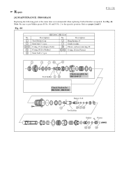
... Q'ty Fastening Torque 18 M6 x 25 Hex socket head bolt 4 7.8 - 11.8 N.m 400 Drill chuck 1 34.3 - 44.1 N.m 18 Quick Change Drill Chuck (Standard Equipment for HR3210FCT) Barrel complete Crank Housing Complete 400 Chuck holder Fig. 42 Upper side Flat washer 5 Triangle mark of Screw and Bolt Fasten Bolts and Drill... chuck to the specific fastening torque. Lower side [3] DISASSEMBLY/ASSEMBLY [3] -8. Fastening Torque of Dust cover support P 20 /24 5x40 Tapping screw: 2 pcs...
... Q'ty Fastening Torque 18 M6 x 25 Hex socket head bolt 4 7.8 - 11.8 N.m 400 Drill chuck 1 34.3 - 44.1 N.m 18 Quick Change Drill Chuck (Standard Equipment for HR3210FCT) Barrel complete Crank Housing Complete 400 Chuck holder Fig. 42 Upper side Flat washer 5 Triangle mark of Screw and Bolt Fasten Bolts and Drill... chuck to the specific fastening torque. Lower side [3] DISASSEMBLY/ASSEMBLY [3] -8. Fastening Torque of Dust cover support P 20 /24 5x40 Tapping screw: 2 pcs...
Technical Reference
Page 21
Note: Be sure to put Makita grease R No. 00 and N No. 2 to pages 2 and 3. Tool holder Chuck assembly for HR3210FCT Chuck Section for Piston) Steel ball 6: 3 pcs. Fig. 44 No. 2 6 26 27 41 10 HR3200C, HR3210C Description No. Description Tool Holder Cap 3 Ring Spring 19 Steel ball 7: 2 pcs. 7 Guide washer O ring 15 (for Impact bolt...
Note: Be sure to put Makita grease R No. 00 and N No. 2 to pages 2 and 3. Tool holder Chuck assembly for HR3210FCT Chuck Section for Piston) Steel ball 6: 3 pcs. Fig. 44 No. 2 6 26 27 41 10 HR3200C, HR3210C Description No. Description Tool Holder Cap 3 Ring Spring 19 Steel ball 7: 2 pcs. 7 Guide washer O ring 15 (for Impact bolt...


