
Parts Breakdown
Page 2
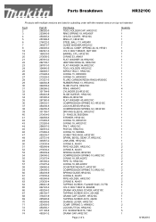
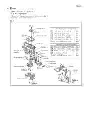
... SPRING 10,HR3210C SPRING GUIDE,HR3210C O RING 8, AN451 PIPE HOLDER, HR3210C O RING 8, AN451 TAPPING SCREW, FLANGE 5X25, 5177B H.S.H. HR3210C O RING 53, AN451 FLAT WASHER 34,HR3210C URETHAN RING 34, HR3210C FLAT WASHER 34,HR3210C TOOL HOLDER, HR3210C IMPACT BOLT, HR3210C O RING 15, HR3000C O RING 15, HR3000C FLURO CARBON RESIN RING,HR3000C RUBBER RING 13, HR3210C SLIDE PLATE, HR3210C PIN 6, HR4041C CYLINDER 25,HR3210C SLIDE SLEEVE, HR3210C RING 29,HR3210C FLAT WASHER 40,HR3210C COMPRESSION SPRING 42, HR3210C LOCK SLEEVE,HR3210C COMPRESSION SPRING 34, HR3210C DRIVING SLEEVE, HR3210C O - SPRING...
... SPRING 10,HR3210C SPRING GUIDE,HR3210C O RING 8, AN451 PIPE HOLDER, HR3210C O RING 8, AN451 TAPPING SCREW, FLANGE 5X25, 5177B H.S.H. HR3210C O RING 53, AN451 FLAT WASHER 34,HR3210C URETHAN RING 34, HR3210C FLAT WASHER 34,HR3210C TOOL HOLDER, HR3210C IMPACT BOLT, HR3210C O RING 15, HR3000C O RING 15, HR3000C FLURO CARBON RESIN RING,HR3000C RUBBER RING 13, HR3210C SLIDE PLATE, HR3210C PIN 6, HR4041C CYLINDER 25,HR3210C SLIDE SLEEVE, HR3210C RING 29,HR3210C FLAT WASHER 40,HR3210C COMPRESSION SPRING 42, HR3210C LOCK SLEEVE,HR3210C COMPRESSION SPRING 34, HR3210C DRIVING SLEEVE, HR3210C O - SPRING...
Parts Breakdown
Page 3
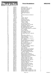
...-0 CORD GUARD 10, HM1202C 1 136 664276-9 CORD (2X16X16 SJ), HR5000 1 137 266041-8 TAPPING SCREW, FLANGE 5X25, 5177B 2 138 266041-8 TAPPING SCREW, FLANGE 5X25, 5177B 2 Page 3 of 4 8/18/2010 Parts Breakdown HR3210C 75 213223-3 O RING 16, AF502 1 76 158437-6 SPUR GEAR 33 CPL,HR3210C 1 77 424064-4 SEAL RING B, HR3210C 1 78 345868-0 LINK PLATE, HR3210C 1 79 450247-0 AIR PIPE, HR3210C 1 80 263005-3 RUBBER PIN 6,LS1013 2 81 450242-0 GEAR SHAFT,HR3210C...
...-0 CORD GUARD 10, HM1202C 1 136 664276-9 CORD (2X16X16 SJ), HR5000 1 137 266041-8 TAPPING SCREW, FLANGE 5X25, 5177B 2 138 266041-8 TAPPING SCREW, FLANGE 5X25, 5177B 2 Page 3 of 4 8/18/2010 Parts Breakdown HR3210C 75 213223-3 O RING 16, AF502 1 76 158437-6 SPUR GEAR 33 CPL,HR3210C 1 77 424064-4 SEAL RING B, HR3210C 1 78 345868-0 LINK PLATE, HR3210C 1 79 450247-0 AIR PIPE, HR3210C 1 80 263005-3 RUBBER PIN 6,LS1013 2 81 450242-0 GEAR SHAFT,HR3210C...
Parts Breakdown
Page 4
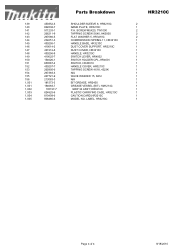
... M5X20, TW1000 TAPPING SCREW 5X40, HK0500 FLAT WASHER 5, HR3210C COMPRESSION SPRING 11, HR3210C HANDLE BASE, HR3210C DUST COVER SUPPORT, HR3210C DUST COVER, HR3210C HANDLE, HR3210C SWITCH LEVER, HR4002 SWITCH HOLDER CPL.,HR4001 SWITCH, HR4001C HANDLE COVER, HR3210C TAPPING SCREW 4X18, 4323K N/A WAVE WASHER 15, 6812 N/A BIT GREASE, HR2400 GREASE VESSEL (BIT), HM1214C GRIP 36 ASS'Y,HR3210C PLASTIC CARRYING CASE, HR3210C CAUTION CARD,HR3210C MODEL NO. LABEL, HR3210C HR3210C 2 1 2 2 2 1 1 1 1 ...135197-7 824825-6 810409-6 806480-6 Parts Breakdown SHOULDER SLEEVE 6, HR3210C NAME PLATE, HR3210C P.H.
... M5X20, TW1000 TAPPING SCREW 5X40, HK0500 FLAT WASHER 5, HR3210C COMPRESSION SPRING 11, HR3210C HANDLE BASE, HR3210C DUST COVER SUPPORT, HR3210C DUST COVER, HR3210C HANDLE, HR3210C SWITCH LEVER, HR4002 SWITCH HOLDER CPL.,HR4001 SWITCH, HR4001C HANDLE COVER, HR3210C TAPPING SCREW 4X18, 4323K N/A WAVE WASHER 15, 6812 N/A BIT GREASE, HR2400 GREASE VESSEL (BIT), HM1214C GRIP 36 ASS'Y,HR3210C PLASTIC CARRYING CASE, HR3210C CAUTION CARD,HR3210C MODEL NO. LABEL, HR3210C HR3210C 2 1 2 2 2 1 1 1 1 ...135197-7 824825-6 810409-6 806480-6 Parts Breakdown SHOULDER SLEEVE 6, HR3210C NAME PLATE, HR3210C P.H.
Technical Reference
Page 1
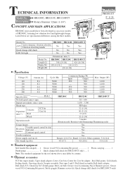
... Impacts per minute: min-1= ipm Shank type Concrete Capacities: mm (") Steel TCT bit Core bit Wood Operation mode Torque limiter Variable speed control by country. Listed below are specification differences among the three models. Optional accessories Plastic carrying 1 TCT bits (taper shank), Taper shank adapter, Cotter, Core bits, Center bit, Core bit adapter , Rod, Bull points, Cold chisels, Scaling chisels, Grooving chisels, Scraper assembly, Dust cups 5 and 9, Drill chuck assembly,Drill chuck adapter, Drill chuck S13, Chuck key S13, Depth gauge...
... Impacts per minute: min-1= ipm Shank type Concrete Capacities: mm (") Steel TCT bit Core bit Wood Operation mode Torque limiter Variable speed control by country. Listed below are specification differences among the three models. Optional accessories Plastic carrying 1 TCT bits (taper shank), Taper shank adapter, Cotter, Core bits, Center bit, Core bit adapter , Rod, Bull points, Cold chisels, Scaling chisels, Grooving chisels, Scraper assembly, Dust cups 5 and 9, Drill chuck assembly,Drill chuck adapter, Drill chuck S13, Chuck key S13, Depth gauge...

Technical Reference
Page 2
... Screwdriver magnetizer Magnetizing Screwdriver when removing Pin and Steel ball 1R230 1/4" Hex. Item No. No.00 (Part No. 181490-7: Hammer grease 30g) to the following portions designated with the instruction manual! [1] NECESSARY REPAIRING TOOLS Code No. Repair P 2 /24 CAUTION: Unplug the tool and remove the bit for safety before repair/ maintenance in Cylinder 25 a 48 Spiral bevel gear 37 Gear teeth 76 Spur gear 33 complete Gear teeth 81 Gear shaft Gear teeth 86 Crank gear Gear...
... Screwdriver magnetizer Magnetizing Screwdriver when removing Pin and Steel ball 1R230 1/4" Hex. Item No. No.00 (Part No. 181490-7: Hammer grease 30g) to the following portions designated with the instruction manual! [1] NECESSARY REPAIRING TOOLS Code No. Repair P 2 /24 CAUTION: Unplug the tool and remove the bit for safety before repair/ maintenance in Cylinder 25 a 48 Spiral bevel gear 37 Gear teeth 76 Spur gear 33 complete Gear teeth 81 Gear shaft Gear teeth 86 Crank gear Gear...
Technical Reference
Page 4
... 4x18 Tapping screws are used 4x18 Tapping screws 8pcs. Pay attention not to Cord clamp base 1pc. Fig. 4 P 4 / 24 69 4x18 Change lever 67 4x14 67 4x14 Crank cap cover 4x14 Tapping screw for tightening: 69 Change lever to Spur gear 33 comp. 1pc. 124 Rear cover to Motor housing 2pcs. 125 Brush holder unit to Motor housing 4pcs. 153 Handle cover to Handle 1pc. Spur gear 33 complete Motor housing...
... 4x18 Tapping screws are used 4x18 Tapping screws 8pcs. Pay attention not to Cord clamp base 1pc. Fig. 4 P 4 / 24 69 4x18 Change lever 67 4x14 67 4x14 Crank cap cover 4x14 Tapping screw for tightening: 69 Change lever to Spur gear 33 comp. 1pc. 124 Rear cover to Motor housing 2pcs. 125 Brush holder unit to Motor housing 4pcs. 153 Handle cover to Handle 1pc. Spur gear 33 complete Motor housing...
Technical Reference
Page 5
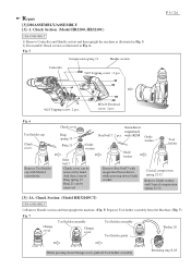
... holder assembly Change cover Tool holder assembly Tool holder guide Washer 28 While pressing down Guide washer. Repair [3] DISASSEMBLY/ASSEMBLY [3] -1. Chuck Section (Model HR3200, HR3210C) DISASSEMBLY 1) Remove Controller and Handle section and then upright the machine as illustrated in Fig. 5. 2) Disassemble Chuck section as illustrated in Fig. 6. Fig. 5 Compression spring 11 Handle section Controller 5x25 Tapping screw : 2 pcs. Guide washer Tool holder Conical compression spring 22-32 Remove Guide washer and Conical compression spring 22-32. [3] -1A. M5x20 Pan head...
... holder assembly Change cover Tool holder assembly Tool holder guide Washer 28 While pressing down Guide washer. Repair [3] DISASSEMBLY/ASSEMBLY [3] -1. Chuck Section (Model HR3200, HR3210C) DISASSEMBLY 1) Remove Controller and Handle section and then upright the machine as illustrated in Fig. 5. 2) Disassemble Chuck section as illustrated in Fig. 6. Fig. 5 Compression spring 11 Handle section Controller 5x25 Tapping screw : 2 pcs. Guide washer Tool holder Conical compression spring 22-32 Remove Guide washer and Conical compression spring 22-32. [3] -1A. M5x20 Pan head...
Technical Reference
Page 6
... Compression spring 42 Change ring Tool Washer 28 holder Ring spring 34 1. Screwdriver magnetized with magnetized Screwdriver while pressing down Washer 28. Guide washer Tool holder Conical compression spring 22-32 Remove Guide washer and Conical compression spring 22-32. The rear parts can be removed. Remove Change cover. 3. Remove Change ring from Change ring. 2. Fig. 11 Tool holder cap Chuck cover Tool holder Remove Tool holder cap with 1R269 while pressing down Guide washer. And then, remove Ring spring 19. Ring 21 can be slung by hand. Chuck...
... Compression spring 42 Change ring Tool Washer 28 holder Ring spring 34 1. Screwdriver magnetized with magnetized Screwdriver while pressing down Washer 28. Guide washer Tool holder Conical compression spring 22-32 Remove Guide washer and Conical compression spring 22-32. The rear parts can be removed. Remove Change cover. 3. Remove Change ring from Change ring. 2. Fig. 11 Tool holder cap Chuck cover Tool holder Remove Tool holder cap with 1R269 while pressing down Guide washer. And then, remove Ring spring 19. Ring 21 can be slung by hand. Chuck...
Technical Reference
Page 7
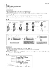
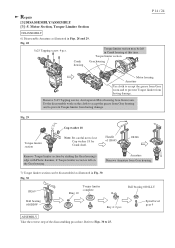
..., 10, 9 and 7. Fig. 13 Tool holder section M4x16 Hex socket head bolt: 1 pc. Chuck Section (Model HR3210FCT) ASSEMBLY Fig. 12 Take the reverse steps of Washer 28. (Fig. 12) Compression spring 42 Groove P 7 / 24 Washer 28 [3] -2. Oil seal Barrel complete From Barrel Complete, Oil seal can be removed as illustrated in Figs 5 and 7. (HR3210FCT) 2) Disassemble Tool holder section (HR3210FCT: Tool holder guide section) together with Cylinder section...
..., 10, 9 and 7. Fig. 13 Tool holder section M4x16 Hex socket head bolt: 1 pc. Chuck Section (Model HR3210FCT) ASSEMBLY Fig. 12 Take the reverse steps of Washer 28. (Fig. 12) Compression spring 42 Groove P 7 / 24 Washer 28 [3] -2. Oil seal Barrel complete From Barrel Complete, Oil seal can be removed as illustrated in Figs 5 and 7. (HR3210FCT) 2) Disassemble Tool holder section (HR3210FCT: Tool holder guide section) together with Cylinder section...
Technical Reference
Page 8
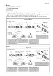
... be replaced in the next step. 3A) HR3210FCT: Separate Tool holder guide section from Cylinder section, and remove Impact bolt from Tool holder. 4. HR3210FCT Pin 6: 4 pcs. Apply magnetized Screwdriver to Cylinder 25: 4 pcs. Repair [3] DISASSEMBLY/ASSEMBLY [3] -2. Remove Pin 6 with 1R288 Cylinder 25 Tool holder Pin 6 Cylinder 25 Tool holder 1. Fig. 14A Flat washer 34: 2 pcs. Remove Pin 6 with 1R288 Pin 6 Tool holder guide Cylinder 25 Tool holder guide Cylinder section Striker Remove Tool holder guide and Striker from Cylinder 25. Cylinder section Striker Remove Tool holder...
... be replaced in the next step. 3A) HR3210FCT: Separate Tool holder guide section from Cylinder section, and remove Impact bolt from Tool holder. 4. HR3210FCT Pin 6: 4 pcs. Apply magnetized Screwdriver to Cylinder 25: 4 pcs. Repair [3] DISASSEMBLY/ASSEMBLY [3] -2. Remove Pin 6 with 1R288 Cylinder 25 Tool holder Pin 6 Cylinder 25 Tool holder 1. Fig. 14A Flat washer 34: 2 pcs. Remove Pin 6 with 1R288 Pin 6 Tool holder guide Cylinder 25 Tool holder guide Cylinder section Striker Remove Tool holder guide and Striker from Cylinder 25. Cylinder section Striker Remove Tool holder...
Technical Reference
Page 10
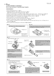
Repair [3] DISASSEMBLY/ASSEMBLY [3] -3. Join the assembled Cylinder section to Tool holder (Tool holder guide) side as illustrated in Fig. 19. Refer to Figs. 19 and 18. Align Slide plate with Pin 6. Cylinder Section P 10 / 24 DISASSEMBLY 1) HR3200C, HR3210C: Disassemble Chuck section. (Figs. 5 and 6) HR3210FCT: Disassemble Tool holder assembly. (Figs. 5 and 7) 2) After removing Crank housing cover, disassemble Barrel complete, and separate Tool holder section from Barrel complete. (Fig. 13) 3) Separate Tool holder section...
Repair [3] DISASSEMBLY/ASSEMBLY [3] -3. Join the assembled Cylinder section to Tool holder (Tool holder guide) side as illustrated in Fig. 19. Refer to Figs. 19 and 18. Align Slide plate with Pin 6. Cylinder Section P 10 / 24 DISASSEMBLY 1) HR3200C, HR3210C: Disassemble Chuck section. (Figs. 5 and 6) HR3210FCT: Disassemble Tool holder assembly. (Figs. 5 and 7) 2) After removing Crank housing cover, disassemble Barrel complete, and separate Tool holder section from Barrel complete. (Fig. 13) 3) Separate Tool holder section...
Technical Reference
Page 11
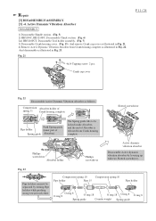
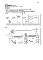
... of Spring guide Absorber). Repair [3] DISASSEMBLY/ASSEMBLY [3] -4. Fig. 21 4x14 Tapping screw: 2 pcs. The Spring guide tilts to be separated by levering up with two Slotted screwdriver. Phillips screwdriver Absorber holder Phillips screwdriver Active dynamic vibration absorber Disassemble Active dynamic vibration absorber by turning Pipe holders while pushing strong toward each other. Active Dynamic Vibration Absorber DISASSEMBLY 1) Disassemble Handle section. (Fig. 5) 2) HR3200C, HR3210FC: Disassemble Chuck section...
... of Spring guide Absorber). Repair [3] DISASSEMBLY/ASSEMBLY [3] -4. Fig. 21 4x14 Tapping screw: 2 pcs. The Spring guide tilts to be separated by levering up with two Slotted screwdriver. Phillips screwdriver Absorber holder Phillips screwdriver Active dynamic vibration absorber Disassemble Active dynamic vibration absorber by turning Pipe holders while pushing strong toward each other. Active Dynamic Vibration Absorber DISASSEMBLY 1) Disassemble Handle section. (Fig. 5) 2) HR3200C, HR3210FC: Disassemble Chuck section...
Technical Reference
Page 12
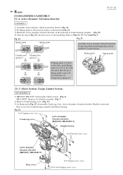
... dymamic vibration absorber (HR3210C, HR3210FCT) Handle Section 5x20 Pan head screw: 2 pcs. Refer to Fig. 23. 2) Set Spring guide to be stuck and check that the tip of Spring guide comes out by pressing while maintaining the position parallel to Figs 21, 13, 7 or 6 and Fig. 5. Motor Section, Torque Limiter Section DISASSEMBLY 1) HR3200C, HR3210C: Disassemble Chuck section. (Fig. 6). HR3210FCT: Remove Tool holder assembly. (Fig. 7) 2) Remove Crank housing cover...
... dymamic vibration absorber (HR3210C, HR3210FCT) Handle Section 5x20 Pan head screw: 2 pcs. Refer to Fig. 23. 2) Set Spring guide to be stuck and check that the tip of Spring guide comes out by pressing while maintaining the position parallel to Figs 21, 13, 7 or 6 and Fig. 5. Motor Section, Torque Limiter Section DISASSEMBLY 1) HR3200C, HR3210C: Disassemble Chuck section. (Fig. 6). HR3210FCT: Remove Tool holder assembly. (Fig. 7) 2) Remove Crank housing cover...
Technical Reference
Page 14
... 29. And separate Motor housing from Gear housing. 7) Torque limiter section can be left on the cloth to accept the grease from Gear housing and to provent Torque limiter from having damage. Do the disassemble work on the Gear housing. Spiral bevel gear 9 ASSEMBLY Take the reverse step of 1R045 1R346 Armature Remove Armature from Gear room. Repair [3] DISASSEMBLY/ASSEMBLY [3] -5. Handle of the disassembling procedure...
... 29. And separate Motor housing from Gear housing. 7) Torque limiter section can be left on the cloth to accept the grease from Gear housing and to provent Torque limiter from having damage. Do the disassemble work on the Gear housing. Spiral bevel gear 9 ASSEMBLY Take the reverse step of 1R045 1R346 Armature Remove Armature from Gear room. Repair [3] DISASSEMBLY/ASSEMBLY [3] -5. Handle of the disassembling procedure...
Technical Reference
Page 15
... Motor housing. (Fig. 25) 7) Disconnect the contact between Carbon brush and Commutator. (Fig. 27) 8) Separate Crank housing complete from Pin of Fig. 28, disassemble it is omitted to set Change lever to the dead point on Crank cap cover Fig. 32 M4x16 Pan head screw: 5 pcs. Repair [3] DISASSEMBLY/ASSEMBLY [3] -6. Spiral bevel gear 37 Spiral bevel gear 37 and Link arm can be removed. Fig. 31 Set Change lever to remove...
... Motor housing. (Fig. 25) 7) Disconnect the contact between Carbon brush and Commutator. (Fig. 27) 8) Separate Crank housing complete from Pin of Fig. 28, disassemble it is omitted to set Change lever to the dead point on Crank cap cover Fig. 32 M4x16 Pan head screw: 5 pcs. Repair [3] DISASSEMBLY/ASSEMBLY [3] -6. Spiral bevel gear 37 Spiral bevel gear 37 and Link arm can be removed. Fig. 31 Set Change lever to remove...
Technical Reference
Page 17
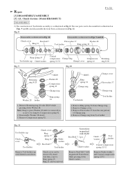
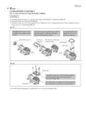
... this notch to assemble the Gear unit in Fig. 37. And then, mount the Crank section to remove the Retaining ring. Consequently, it as illustrated in Fig. 36R. 2) Assemble Gears for changing operation mode as illustrated in Rotary hammer mode exactly. Fig. 37 Crank gear Gear shaft These notches are important Marks to Pin. Repair [3] DISASSEMBLY/ASSEMBLY [3] -6. Crank housing complete Gear shaft Insert Crank gear while fitting this...
... this notch to assemble the Gear unit in Fig. 37. And then, mount the Crank section to remove the Retaining ring. Consequently, it as illustrated in Fig. 36R. 2) Assemble Gears for changing operation mode as illustrated in Rotary hammer mode exactly. Fig. 37 Crank gear Gear shaft These notches are important Marks to Pin. Repair [3] DISASSEMBLY/ASSEMBLY [3] -6. Crank housing complete Gear shaft Insert Crank gear while fitting this...
Technical Reference
Page 18
... parts by fitting its bosses to Crank housing complete while keeping Change lever in the position illustrated in Crank housing complete. Push Link arm into sight. Repair [3] DISASSEMBLY/ASSEMBLY [3] -6. Spiral bevel gear 37 Notches of The notches of Link arm. Assemble Link plate by taking the reverse of Spur gear 33 complete which is fit into sight in Fig. 31A. Pin...
... parts by fitting its bosses to Crank housing complete while keeping Change lever in the position illustrated in Crank housing complete. Push Link arm into sight. Repair [3] DISASSEMBLY/ASSEMBLY [3] -6. Spiral bevel gear 37 Notches of The notches of Link arm. Assemble Link plate by taking the reverse of Spur gear 33 complete which is fit into sight in Fig. 31A. Pin...
Technical Reference
Page 19
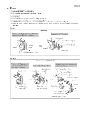
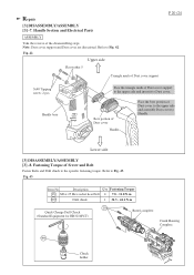
... Dust cover support Dust cover Lead unit ON-OFF Switch Handle base 5x25 Tapping screw: 2 pcs. Handle Section and Electrical Parts DISASSEMBLY 1) Disassemble Handle section as illustrated in Fig. 41A. Handle cover 4x18 Tapping screw: 1 pc. Flat washer 5: 2 pcs. Handle Fig. 41 HR3200C Unscrew 4x18 Tapping screw. Replace ON-OFF Switch etc. Handle Section can be disassembled as illustrated in Fig. 25 and 26. 2) Controller and Power supply cord can be removed...
... Dust cover support Dust cover Lead unit ON-OFF Switch Handle base 5x25 Tapping screw: 2 pcs. Handle Section and Electrical Parts DISASSEMBLY 1) Disassemble Handle section as illustrated in Fig. 41A. Handle cover 4x18 Tapping screw: 1 pc. Flat washer 5: 2 pcs. Handle Fig. 41 HR3200C Unscrew 4x18 Tapping screw. Replace ON-OFF Switch etc. Handle Section can be disassembled as illustrated in Fig. 25 and 26. 2) Controller and Power supply cord can be removed...
Technical Reference
Page 20
... and insert it to the specific fastening torque. Lower side [3] DISASSEMBLY/ASSEMBLY [3] -8. Description Q'ty Fastening Torque 18 M6 x 25 Hex socket head bolt 4 7.8 - 11.8 N.m 400 Drill chuck 1 34.3 - 44.1 N.m 18 Quick Change Drill Chuck (Standard Equipment for HR3210FCT) Barrel complete Crank Housing Complete 400 Chuck holder Note: Dust cover support and Dust cover are directional. Handle Section and Electrical Parts ASSEMBLY Take the reverse of Dust cover support P 20 /24 5x40 Tapping screw: 2 pcs...
... and insert it to the specific fastening torque. Lower side [3] DISASSEMBLY/ASSEMBLY [3] -8. Description Q'ty Fastening Torque 18 M6 x 25 Hex socket head bolt 4 7.8 - 11.8 N.m 400 Drill chuck 1 34.3 - 44.1 N.m 18 Quick Change Drill Chuck (Standard Equipment for HR3210FCT) Barrel complete Crank Housing Complete 400 Chuck holder Note: Dust cover support and Dust cover are directional. Handle Section and Electrical Parts ASSEMBLY Take the reverse of Dust cover support P 20 /24 5x40 Tapping screw: 2 pcs...
Technical Reference
Page 21
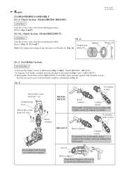
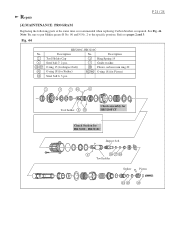
... (for Striker) 42 46 O ring 18 (for HR3200C, HR3210C Impact bolt Tool holder Striker Piston Fig. 44 No. 2 6 26 27 41 10 HR3200C, HR3210C Description No. See Fig. 44. Repair P 21 / 24 [4] MAINTENANCE PROGRAM Replacing the following parts at the same time is recommended when replacing Carbon brushes is required. Refer to the specific portions. Tool holder Chuck assembly for HR3210FCT Chuck Section for Piston) Steel ball 6: 3 pcs.
... (for Striker) 42 46 O ring 18 (for HR3200C, HR3210C Impact bolt Tool holder Striker Piston Fig. 44 No. 2 6 26 27 41 10 HR3200C, HR3210C Description No. See Fig. 44. Repair P 21 / 24 [4] MAINTENANCE PROGRAM Replacing the following parts at the same time is recommended when replacing Carbon brushes is required. Refer to the specific portions. Tool holder Chuck assembly for HR3210FCT Chuck Section for Piston) Steel ball 6: 3 pcs.


