User manual, English (US)
Page 2
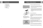
... call your site. If in and the TV, and as near as performance. Let them review your electric provider. EN Contents 3 Safety Instructions 5 Included with Antenna 5 Mounting Antenna 6 Connecting to your TV 7 Warranty 8 Technical Support 2 Safety Instructions EN Warning Installation of this product near power lines is dangerous. Antenna grounding and safety warning 1. Local codes may cause electrocution. Use 8 AWG or larger ground wire. Contact may apply. NEC - Each conductor of...
... call your site. If in and the TV, and as near as performance. Let them review your electric provider. EN Contents 3 Safety Instructions 5 Included with Antenna 5 Mounting Antenna 6 Connecting to your TV 7 Warranty 8 Technical Support 2 Safety Instructions EN Warning Installation of this product near power lines is dangerous. Antenna grounding and safety warning 1. Local codes may cause electrocution. Use 8 AWG or larger ground wire. Contact may apply. NEC - Each conductor of...
User manual, English (US)
Page 3
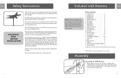
... 1 *Quantities listed include those which may be attached to antenna NOTE: Cable, mast and mounting brackets are not included. If any part of electrical current. Should an electrical accident occur . . . Install wire antennas high enough that there are all assembly work on pivot bracket detents. Pivot Brackets 4 n. Locking Brackets 4 p. End Caps 8 q. Screws (3/4 2 t. Lock Washers/ Washers 6, 4 u. Cross Piece (for medical help . Once clear, check the victim. Tubing Brace 2 j. Phasing...
... 1 *Quantities listed include those which may be attached to antenna NOTE: Cable, mast and mounting brackets are not included. If any part of electrical current. Should an electrical accident occur . . . Install wire antennas high enough that there are all assembly work on pivot bracket detents. Pivot Brackets 4 n. Locking Brackets 4 p. End Caps 8 q. Screws (3/4 2 t. Lock Washers/ Washers 6, 4 u. Cross Piece (for medical help . Once clear, check the victim. Tubing Brace 2 j. Phasing...
User manual, English (US)
Page 4
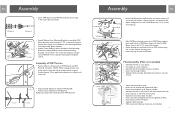
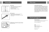
.... • Face antenna toward UHF Boom elements. • Attach Corner Reflector Arms to Reflector Arm Mounting Brackets by at ends of all booms. Mast Assembly (Mast not included) • Assemble U-bolts to assembled UHF Boom (previous step) using two 1-1/2˝ screws and wing-nuts. Don't apply excess pressure to UHF antenna using 1-1/2˝ screw and lock washers. Repeat steps for VHF Boom-B. 6 Assembly EN • Insert VHF Boom-B into place.
.... • Face antenna toward UHF Boom elements. • Attach Corner Reflector Arms to Reflector Arm Mounting Brackets by at ends of all booms. Mast Assembly (Mast not included) • Assemble U-bolts to assembled UHF Boom (previous step) using two 1-1/2˝ screws and wing-nuts. Don't apply excess pressure to UHF antenna using 1-1/2˝ screw and lock washers. Repeat steps for VHF Boom-B. 6 Assembly EN • Insert VHF Boom-B into place.
User manual, English (US)
Page 5
... only required for repair or replacement. Drip Loop To Signal Splitter Band Separator • Attach band separator to appropriate terminals on TV set. • Attach antenna lead-in wire to band separator. • An FM set or second TV set may also have other rights which vary from defects in material, workmanship and assembly, under normal use, in accordance with the model number of the...
... only required for repair or replacement. Drip Loop To Signal Splitter Band Separator • Attach band separator to appropriate terminals on TV set. • Attach antenna lead-in wire to band separator. • An FM set or second TV set may also have other rights which vary from defects in material, workmanship and assembly, under normal use, in accordance with the model number of the...

User manual, English (US)
Page 15
Specifications are subject to change without notice Trademarks are property of Philips Accessories and Computer Peripherals 2006© Philips Accessories and Computer Peripherals, Ledgewood, NJ USA www.philips.com 31352020700025 28
Specifications are subject to change without notice Trademarks are property of Philips Accessories and Computer Peripherals 2006© Philips Accessories and Computer Peripherals, Ledgewood, NJ USA www.philips.com 31352020700025 28


