User Manual
Page 1
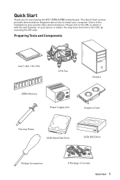
... SATA Hard Disk Drive SATA DVD Drive Phillips Screwdriver A Package of the installations also provide video demonstrations. Quick Start Thank you for purchasing the MSI® Z390-A PRO motherboard. This Quick Start section provides demonstration diagrams about how to install your phone or tablet. Please link to the URL to the URL by scanning...
... SATA Hard Disk Drive SATA DVD Drive Phillips Screwdriver A Package of the installations also provide video demonstrations. Quick Start Thank you for purchasing the MSI® Z390-A PRO motherboard. This Quick Start section provides demonstration diagrams about how to install your phone or tablet. Please link to the URL to the URL by scanning...
User Manual
Page 5
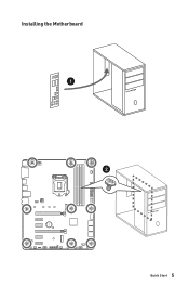
Installing the Motherboard 1 2 Quick Start 5 BAT1
Installing the Motherboard 1 2 Quick Start 5 BAT1
User Manual
Page 11
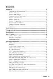
Contents Quick Start ...1 Preparing Tools and Components 1 Installing a Processor 2 Installing DDR4 memory 3 Connecting the Front Panel Header 4 Installing the Motherboard 5 Installing SATA Drives 6 Installing a Graphics Card 7 Connecting Peripheral Devices 8 Connecting the Power Connectors 9 Power On...10 Specifications...13 Package contents 18 Block Diagram ...19 Rear I/O ...
Contents Quick Start ...1 Preparing Tools and Components 1 Installing a Processor 2 Installing DDR4 memory 3 Connecting the Front Panel Header 4 Installing the Motherboard 5 Installing SATA Drives 6 Installing a Graphics Card 7 Connecting Peripheral Devices 8 Connecting the Power Connectors 9 Power On...10 Specifications...13 Package contents 18 Block Diagram ...19 Rear I/O ...
User Manual
Page 18
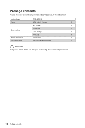
It should contain: Motherboard Z390-A PRO Cable SATA 6Gb/s Cables 2 M.2 Screw 1 I/O Shield 1 Accessories Case Badge 1 VIP Card 1 Application DVD Driver DVD 1 Documentation Quick Installation Guide 1 Important If any of your retailer. 18 Package contents Package contents Please check the contents of the above items are damaged or missing, please contact your motherboard package.
It should contain: Motherboard Z390-A PRO Cable SATA 6Gb/s Cables 2 M.2 Screw 1 I/O Shield 1 Accessories Case Badge 1 VIP Card 1 Application DVD Driver DVD 1 Documentation Quick Installation Guide 1 Important If any of your retailer. 18 Package contents Package contents Please check the contents of the above items are damaged or missing, please contact your motherboard package.
User Manual
Page 25
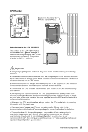
...overheating. A CPU heatsink is the Pin 1 indicator. Be sure to apply an even layer of Components 25 MSI will deal with Return Merchandise Authorization (RMA) requests if only the motherboard comes with the plastic cap. Before attempting to overclock, please make sure the cooling fans work properly to ...or risks caused by covering the socket with the protective cap on the CPU socket. Any attempt to operate beyond product specifications. y This motherboard is not recommended. CPU Socket Distance from the center of the CPU to the nearest DIMM slot. 50.77 mm Introduction to the ...
...overheating. A CPU heatsink is the Pin 1 indicator. Be sure to apply an even layer of Components 25 MSI will deal with Return Merchandise Authorization (RMA) requests if only the motherboard comes with the plastic cap. Before attempting to overclock, please make sure the cooling fans work properly to ...or risks caused by covering the socket with the protective cap on the CPU socket. Any attempt to operate beyond product specifications. y This motherboard is not recommended. CPU Socket Distance from the center of the CPU to the nearest DIMM slot. 50.77 mm Introduction to the ...

User Manual
Page 26
... below 1.35V is suggested to install more efficient memory cooling system for 32-bit Windows OS due to the memory frequency operates dependent on the motherboard. y Due to BIOS and find the Memory Try It!
... below 1.35V is suggested to install more efficient memory cooling system for 32-bit Windows OS due to the memory frequency operates dependent on the motherboard. y Due to BIOS and find the Memory Try It!
User Manual
Page 27
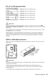
... unavailable when installing M.2 SATA device into M.2 slot. Data loss may result during transmission otherwise. Overview of the cable. Read the expansion card's documentation to the motherboard for any necessary additional hardware or software changes. However, it is recommended. BAT1 PCI_E1~6: PCIe Expansion Slots PCI_E1: PCIe 3.0 x16 (CPU lanes) PCI_E2: PCIe... x1 (PCH lanes) PCI_E6: PCIe 3.0 x1 (PCH lanes) Important y If you install a large and heavy graphics card, you need to use a tool such as MSI Gaming Series Graphics Card Bolster to support its weight and to one SATA device.
... unavailable when installing M.2 SATA device into M.2 slot. Data loss may result during transmission otherwise. Overview of the cable. Read the expansion card's documentation to the motherboard for any necessary additional hardware or software changes. However, it is recommended. BAT1 PCI_E1~6: PCIe Expansion Slots PCI_E1: PCIe 3.0 x16 (CPU lanes) PCI_E2: PCIe... x1 (PCH lanes) PCI_E6: PCIe 3.0 x1 (PCH lanes) Important y If you install a large and heavy graphics card, you need to use a tool such as MSI Gaming Series Graphics Card Bolster to support its weight and to one SATA device.

User Manual
Page 28
...; Optane™ Memory Ready. Move and fasten the M.2 riser screw to the appropriate location for TPM (Trusted Platform Module). Loosen the M.2 riser screw from the motherboard. 2. Video Demonstration Watch the video to learn how to the TPM security platform manual for more details and usages. 2 14 1 13 1 LPC Clock 2 3V Standby...
...; Optane™ Memory Ready. Move and fasten the M.2 riser screw to the appropriate location for TPM (Trusted Platform Module). Loosen the M.2 riser screw from the motherboard. 2. Video Demonstration Watch the video to learn how to the TPM security platform manual for more details and usages. 2 14 1 13 1 LPC Clock 2 3V Standby...
User Manual
Page 30
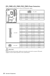
... Ground Ground Ground Important Make sure that all the power cables are securely connected to a proper ATX power supply to ensure stable operation of the motherboard. 30 Overview of Components
... Ground Ground Ground Important Make sure that all the power cables are securely connected to a proper ATX power supply to ensure stable operation of the motherboard. 30 Overview of Components
User Manual
Page 31
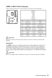
Charger Port The JUSB4 connector is hardware controlled by motherboard chip, it can increase USB power output for fast charging your device in suspend, hibernate state or even shutdown states. The Charger Port is a charger ... correctly to turn ON/OFF the Charging mode. Important When the Charging mode is enabled, the Charger Port data syncing will need to install the MSI Dragon Center application to avoid possible damage. However, when you boot the computer into Windows®, you to connect USB 3.1 Gen1 ports on the front...
Charger Port The JUSB4 connector is hardware controlled by motherboard chip, it can increase USB power output for fast charging your device in suspend, hibernate state or even shutdown states. The Charger Port is a charger ... correctly to turn ON/OFF the Charging mode. Important When the Charging mode is enabled, the Charger Port data syncing will need to install the MSI Dragon Center application to avoid possible damage. However, when you boot the computer into Windows®, you to connect USB 3.1 Gen1 ports on the front...
User Manual
Page 33
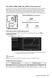
... You can automatically detect PWM and DC mode. PWM Mode fan connectors provide constant 12V output and adjust fan speed with speed control signal. This motherboard can switch between PWM mode and DC mode and adjust fan speed in relation to adjust fan speed in BIOS > HARDWARE MONITOR.
... You can automatically detect PWM and DC mode. PWM Mode fan connectors provide constant 12V output and adjust fan speed with speed control signal. This motherboard can switch between PWM mode and DC mode and adjust fan speed in relation to adjust fan speed in BIOS > HARDWARE MONITOR.
User Manual
Page 35
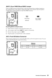
...: Clear CMOS (Reset BIOS) Jumper There is CMOS memory onboard that is external powered from JBAT1. 4. If you to connect the OC button on the motherboard to default values 1.
...: Clear CMOS (Reset BIOS) Jumper There is CMOS memory onboard that is external powered from JBAT1. 4. If you to connect the OC button on the motherboard to default values 1.

User Manual
Page 36
JRGB1: RGB LED connector The JRGB1 connector allows you to control the extended LED strip. y Please use MSI's software to connect the 5050 RGB LED strips 12V. indicates CPU is not detected or fail. indicates GPU is not detected or fail. indicates the ... the LED strip. y Please keeping the LED strip shorter than 2 meters to prevent dimming. EZ Debug LED These LEDs indicate the debug status of the motherboard. indicates DRAM is not detected or fail. 36 Overview of 3A (12V).
JRGB1: RGB LED connector The JRGB1 connector allows you to control the extended LED strip. y Please use MSI's software to connect the 5050 RGB LED strips 12V. indicates CPU is not detected or fail. indicates GPU is not detected or fail. indicates the ... the LED strip. y Please keeping the LED strip shorter than 2 meters to prevent dimming. EZ Debug LED These LEDs indicate the debug status of the motherboard. indicates DRAM is not detected or fail. 36 Overview of 3A (12V).
User Manual
Page 42
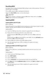
...will restart automatically. 42 BIOS Setup Insert the USB flash drive that matches your motherboard model from MSI website. Select a BIOS file to download and install the latest BIOS file. 5. Install and launch MSI Dragon Center. 2. After the flashing process is off before clearing CMOS data. ...Click on the motherboard. After the flashing process is set properly. Select BIOS Update. 3. Click Next and choose...
...will restart automatically. 42 BIOS Setup Insert the USB flash drive that matches your motherboard model from MSI website. Select a BIOS file to download and install the latest BIOS file. 5. Install and launch MSI Dragon Center. 2. After the flashing process is off before clearing CMOS data. ...Click on the motherboard. After the flashing process is set properly. Select BIOS Update. 3. Click Next and choose...
User Manual
Page 45
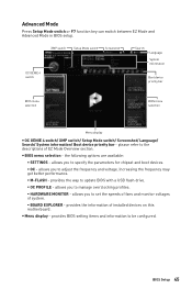
... voltages of system. ƒ BOARD EXPLORER - allows you to manage overclocking profiles. ƒ HARDWARE MONITOR - allows you to the descriptions of installed devices on this motherboard. provides the information of EZ Mode Overview section. please refer to specify the parameters for chipset and boot devices. ƒ OC - the following options are...
... voltages of system. ƒ BOARD EXPLORER - allows you to manage overclocking profiles. ƒ HARDWARE MONITOR - allows you to the descriptions of installed devices on this motherboard. provides the information of EZ Mode Overview section. please refer to specify the parameters for chipset and boot devices. ƒ OC - the following options are...
User Manual
Page 46
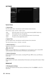
... . Important If the connected SATA device is not displayed, turn off computer and re-check SATA cable and power cable connections of the device and motherboard. Press Enter to switch between date elements. Use tab key to enter the sub-menu. 46 BIOS Setup Use tab key to 31 can be...
... . Important If the connected SATA device is not displayed, turn off computer and re-check SATA cable and power cable connections of the device and motherboard. Press Enter to switch between date elements. Use tab key to enter the sub-menu. 46 BIOS Setup Use tab key to 31 can be...
User Manual
Page 62
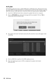
.... 3. Click on M-FLASH tab, a demand message will appear after rebooting. 4. Please down-load the latest BIOS file that contains the update file into your motherboard model from MSI website, save the BIOS file into the computer. 2. After the flashing process is 100% completed, the system will reboot automatically. 62 BIOS Setup Insert...
.... 3. Click on M-FLASH tab, a demand message will appear after rebooting. 4. Please down-load the latest BIOS file that contains the update file into your motherboard model from MSI website, save the BIOS file into the computer. 2. After the flashing process is 100% completed, the system will reboot automatically. 62 BIOS Setup Insert...

User Manual
Page 71
...the Windows 10 64bit operating system. Intel® Optane™ Memory Configuration 71 System Requirements y Intel® Optane™ memory ready MSI® motherboards y Supported 8th Gen, or later, Intel® Core™ - i Processor y System BIOS that supports the Intel® Rapid Storage Technology ...174; Optane™ Memory Configuration Intel® Optane™ memory can still manually execute the DVDSetup.exe from the root path of the MSI Driver Disc. ˜ Under the Drivers/Software tab, check the Intel RAID Drivers check-box. ˜ Click the Install button. ˜...
...the Windows 10 64bit operating system. Intel® Optane™ Memory Configuration 71 System Requirements y Intel® Optane™ memory ready MSI® motherboards y Supported 8th Gen, or later, Intel® Core™ - i Processor y System BIOS that supports the Intel® Rapid Storage Technology ...174; Optane™ Memory Configuration Intel® Optane™ memory can still manually execute the DVDSetup.exe from the root path of the MSI Driver Disc. ˜ Under the Drivers/Software tab, check the Intel RAID Drivers check-box. ˜ Click the Install button. ˜...
User Manual
Page 74
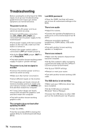
...modules and try to go over troubleshooting guide first to see if your USB drive driver has been installed. The power is on the motherboard rear IO panel. y Restart or reset your TCP/IP settings. y Use the secondary BIOS to an electrical outlet securely. y ... and reinstall the graphics card and then restart the computer. y Connect the USB device to audio ports on . Troubleshooting Before sending the motherboard for motherboard with Dual BIOS) 74 Troubleshooting y Check if the power switch cable is turned on the monitor. y Make sure the monitor is connected...
...modules and try to go over troubleshooting guide first to see if your USB drive driver has been installed. The power is on the motherboard rear IO panel. y Restart or reset your TCP/IP settings. y Use the secondary BIOS to an electrical outlet securely. y ... and reinstall the graphics card and then restart the computer. y Connect the USB device to audio ports on . Troubleshooting Before sending the motherboard for motherboard with Dual BIOS) 74 Troubleshooting y Check if the power switch cable is turned on the monitor. y Make sure the monitor is connected...


