User Manual
Page 11
... JTPM1: TPM Module Connector 28 JFP1, JFP2: Front Panel Connectors 29 JCOM1: Serial Port Connector 29 JTBT1: Thunderbolt Add-on Card Connector 29 CPU_PWR1, ATX_PWR1, PCIE_PWR1: Power Connectors 30 JUSB3~4: USB 3.1 Gen1 Connectors 31 JUSB1~2: USB 2.0 Connectors 32 JLPT1: Parallel Port Connector 32 CPU_FAN1, PUMP_FAN1, SYS_FAN1~5: Fan Connectors 33 JAUD1: Front Audio Connector 34 JCI1: Chassis Intrusion Connector 34 JBAT1: Clear CMOS...
... JTPM1: TPM Module Connector 28 JFP1, JFP2: Front Panel Connectors 29 JCOM1: Serial Port Connector 29 JTBT1: Thunderbolt Add-on Card Connector 29 CPU_PWR1, ATX_PWR1, PCIE_PWR1: Power Connectors 30 JUSB3~4: USB 3.1 Gen1 Connectors 31 JUSB1~2: USB 2.0 Connectors 32 JLPT1: Parallel Port Connector 32 CPU_FAN1, PUMP_FAN1, SYS_FAN1~5: Fan Connectors 33 JAUD1: Front Audio Connector 34 JCI1: Chassis Intrusion Connector 34 JBAT1: Clear CMOS...

User Manual
Page 14
RAID LAN USB Audio Back Panel Connectors Continued from previous page Intel® Z390 Chipset y Supports RAID 0, RAID1, RAID 5 and RAID 10 for details. y Realtek® ALC892 Codec ƒ 7.1-Channel High Definition Audio y 1x PS/2 keyboard/ mouse combo port... I219-V Gigabit LAN controller y Intel® Z390 Chipset ƒ 2x USB 3.1 Gen2 (SuperSpeed USB 10Gbps) ports (1x Type-A port and 1x Type-C port) on the back panel ƒ 6x USB 3.1 Gen1 (SuperSpeed USB) ports (2 Type-A ports on the back panel, 4 ports available through the internal USB 3.1 connectors) ƒ 6x USB 2.0 (High-speed ...
RAID LAN USB Audio Back Panel Connectors Continued from previous page Intel® Z390 Chipset y Supports RAID 0, RAID1, RAID 5 and RAID 10 for details. y Realtek® ALC892 Codec ƒ 7.1-Channel High Definition Audio y 1x PS/2 keyboard/ mouse combo port... I219-V Gigabit LAN controller y Intel® Z390 Chipset ƒ 2x USB 3.1 Gen2 (SuperSpeed USB 10Gbps) ports (1x Type-A port and 1x Type-C port) on the back panel ƒ 6x USB 3.1 Gen1 (SuperSpeed USB) ports (2 Type-A ports on the back panel, 4 ports available through the internal USB 3.1 connectors) ƒ 6x USB 2.0 (High-speed ...

User Manual
Page 15
... additional 4 USB 2.0 ports) y 1x 4-pin CPU fan connector y 1x 4-pin Water Pump connector y 5x 4-pin system fan connectors y 1x Front panel audio connector y 2x System panel connectors y 1x Chassis Intrusion connector y 1x 4-pin RGB LED connector y 1x Serial Port connector y 1x Clear CMOS jumper y 1x Parallel port connector y 1x TPM module connector y 1x thunderbolt Add-on next page Specifications 15...
... additional 4 USB 2.0 ports) y 1x 4-pin CPU fan connector y 1x 4-pin Water Pump connector y 5x 4-pin system fan connectors y 1x Front panel audio connector y 2x System panel connectors y 1x Chassis Intrusion connector y 1x 4-pin RGB LED connector y 1x Serial Port connector y 1x Clear CMOS jumper y 1x Parallel port connector y 1x TPM module connector y 1x thunderbolt Add-on next page Specifications 15...

User Manual
Page 21
... the array of options will pop up asking you plugged in front or rear panel by adjust the bar. y Connector Settings - Application Enhancement Advanced Settings Device Selection Main Volume Connector Settings Jack Status y Device Selection - Auto popup dialog When you plug into a device at an audio jack, a dialogue window will provide you a complete...
... the array of options will pop up asking you plugged in front or rear panel by adjust the bar. y Connector Settings - Application Enhancement Advanced Settings Device Selection Main Volume Connector Settings Jack Status y Device Selection - Auto popup dialog When you plug into a device at an audio jack, a dialogue window will provide you a complete...

User Manual
Page 24
.../B1/B2 DIMM Slots JAUD1 Front Audio Connector JBAT1 Clear CMOS Jumper JCI1 Chassis Intrusion Connector JCOM1 Serial Port Connector JFP1, JFP2 Front Panel Connectors JLPT1 Parallel Port Connector JOC1 Front OC Button Connector JRGB1 JTBT1 JTPM1 RGB LED connector Thunderbolt Add-on Card Connector TPM Module Connector JUSB1~2 USB 2.0 Connectors JUSB3~4 USB 3.1 Gen1 Connectors M2_1 M.2 Slot (Key M) PCI_E1~6 PCIe Expansion Slots...
.../B1/B2 DIMM Slots JAUD1 Front Audio Connector JBAT1 Clear CMOS Jumper JCI1 Chassis Intrusion Connector JCOM1 Serial Port Connector JFP1, JFP2 Front Panel Connectors JLPT1 Parallel Port Connector JOC1 Front OC Button Connector JRGB1 JTBT1 JTPM1 RGB LED connector Thunderbolt Add-on Card Connector TPM Module Connector JUSB1~2 USB 2.0 Connectors JUSB3~4 USB 3.1 Gen1 Connectors M2_1 M.2 Slot (Key M) PCI_E1~6 PCIe Expansion Slots...
User Manual
Page 29
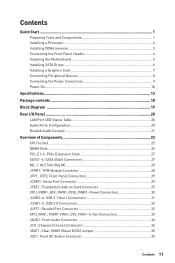
... Panel Connectors These connectors connect to connect the add-on the front panel. Power LED Power Switch - -+ -- ++ JFP1 2 1 + 10 9 Reserved HDD LED Reset Switch 1 HDD LED + 2 3 HDD LED - 4 5 Reset Switch 6 7 Reset Switch 8 9 Reserved 10 Power LED + Power LED Power Switch Power Switch No Pin 1 JFP2 1 Speaker - 2 3 Buzzer - 4 Buzzer + Speaker + JCOM1: Serial Port Connector This connector allows...
... Panel Connectors These connectors connect to connect the add-on the front panel. Power LED Power Switch - -+ -- ++ JFP1 2 1 + 10 9 Reserved HDD LED Reset Switch 1 HDD LED + 2 3 HDD LED - 4 5 Reset Switch 6 7 Reset Switch 8 9 Reserved 10 Power LED + Power LED Power Switch Power Switch No Pin 1 JFP2 1 Speaker - 2 3 Buzzer - 4 Buzzer + Speaker + JCOM1: Serial Port Connector This connector allows...
User Manual
Page 31
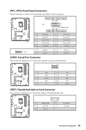
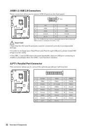
However, when you boot the computer into Windows®, you to connect USB 3.1 Gen1 ports on the front panel. 10 11 1 20 1 Power 11 USB2.0+ 2 USB3_RX_DN 12 USB2.0- 3 USB3_RX_DP 13 Ground 4 Ground 14 USB3_TX_C_DP 5 USB3_TX_C_DN 15 USB3_TX_C_DN 6 USB3_TX_C_DP 16 Ground 7 Ground 17 .... Important When the Charging mode is a charger port which can still charge your smartphone or USB-powered devices. Charger Port The JUSB4 connector is enabled, the Charger Port data syncing will need to install the MSI Dragon Center application to turn ON/OFF the Charging mode.
However, when you boot the computer into Windows®, you to connect USB 3.1 Gen1 ports on the front panel. 10 11 1 20 1 Power 11 USB2.0+ 2 USB3_RX_DN 12 USB2.0- 3 USB3_RX_DP 13 Ground 4 Ground 14 USB3_TX_C_DP 5 USB3_TX_C_DN 15 USB3_TX_C_DN 6 USB3_TX_C_DP 16 Ground 7 Ground 17 .... Important When the Charging mode is a charger port which can still charge your smartphone or USB-powered devices. Charger Port The JUSB4 connector is enabled, the Charger Port data syncing will need to install the MSI Dragon Center application to turn ON/OFF the Charging mode.
User Manual
Page 32
... pins must be connected correctly to recharge your iPad,iPhone and iPod through USB ports, please install MSI Dragon Center utility. JLPT1: Parallel Port Connector This connector allows you to connect USB 2.0 ports on the front panel. 2 10 Note 1 9 1 VCC 2 VCC 3 USB0- 4 USB1- 5 USB0+ 6 USB1+ 7 Ground 8 Ground 9 No Pin 10 NC Important Note : For...
... pins must be connected correctly to recharge your iPad,iPhone and iPod through USB ports, please install MSI Dragon Center utility. JLPT1: Parallel Port Connector This connector allows you to connect USB 2.0 ports on the front panel. 2 10 Note 1 9 1 VCC 2 VCC 3 USB0- 4 USB1- 5 USB0+ 6 USB1+ 7 Ground 8 Ground 9 No Pin 10 NC Important Note : For...
User Manual
Page 34
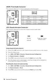
...and then press the Enter key to the chassis intrusion switch/ sensor on . Close the chassis cover. 3. JAUD1: Front Audio Connector This connector allows you to connect audio jacks on the front panel. 2 10 1 9 1 MIC L 2 Ground 3 MIC R 4 NC 5 Head Phone R 6 MIC Detection 7 SENSE_SEND... 8 No Pin 9 Head Phone L 10 Head Phone Detection JCI1: Chassis Intrusion Connector This connector allows you to Reset. 3. Go to select...
...and then press the Enter key to the chassis intrusion switch/ sensor on . Close the chassis cover. 3. JAUD1: Front Audio Connector This connector allows you to connect audio jacks on the front panel. 2 10 1 9 1 MIC L 2 Ground 3 MIC R 4 NC 5 Head Phone R 6 MIC Detection 7 SENSE_SEND... 8 No Pin 9 Head Phone L 10 Head Phone Detection JCI1: Chassis Intrusion Connector This connector allows you to Reset. 3. Go to select...
User Manual
Page 35
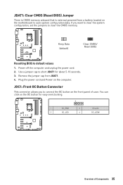
Remove the jumper cap from a battery located on the front panel of Components 35 Keep Data (default) Clear CMOS/ Reset BIOS Resetting BIOS to short JBAT1 for easy overclocking. 1 1 OC_EN# 2 3 OC_LED 4 Ground OC_LED# Overview of case. JOC1: Front OC Button Connector This connector allows you want to clear the system configuration, set the jumpers...
Remove the jumper cap from a battery located on the front panel of Components 35 Keep Data (default) Clear CMOS/ Reset BIOS Resetting BIOS to short JBAT1 for easy overclocking. 1 1 OC_EN# 2 3 OC_LED 4 Ground OC_LED# Overview of case. JOC1: Front OC Button Connector This connector allows you want to clear the system configuration, set the jumpers...
User Manual
Page 74
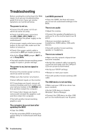
y Check if all ATX power connectors like ATX_PWR1, CPU_PWR1 are properly illuminated. y Test with Dual BIOS) 74 Troubleshooting y... computer. y Check if the power switch cable is connected to other USB port on the motherboard rear IO panel. y Verify the Clear CMOS jumper JBAT1 is properly connected and make sure the button is not working power supply...lose all memory modules and try to go over troubleshooting guide first to audio ports on the motherboard rear IO panel. Lost BIOS password y Clear the CMOS, but no audio y Adjust the volume. There is turned on ...
y Check if all ATX power connectors like ATX_PWR1, CPU_PWR1 are properly illuminated. y Test with Dual BIOS) 74 Troubleshooting y... computer. y Check if the power switch cable is connected to other USB port on the motherboard rear IO panel. y Verify the Clear CMOS jumper JBAT1 is properly connected and make sure the button is not working power supply...lose all memory modules and try to go over troubleshooting guide first to audio ports on the motherboard rear IO panel. Lost BIOS password y Clear the CMOS, but no audio y Adjust the volume. There is turned on ...


