User Manual
Page 13
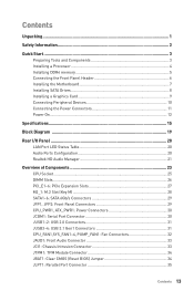
... CPU_FAN1,SYS_FAN1~4, PUMP_FAN1: Fan Connectors 32 JAUD1: Front Audio Connector 33 JCI1: Chassis Intrusion Connector 33 JTPM1: TPM Module Connector 34 JBAT1: Clear CMOS (Reset BIOS) Jumper 34 JLPT1: Parallel Port Connector 35 Contents 13
... CPU_FAN1,SYS_FAN1~4, PUMP_FAN1: Fan Connectors 32 JAUD1: Front Audio Connector 33 JCI1: Chassis Intrusion Connector 33 JTPM1: TPM Module Connector 34 JBAT1: Clear CMOS (Reset BIOS) Jumper 34 JLPT1: Parallel Port Connector 35 Contents 13
User Manual
Page 14
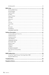
EZ Debug LED...35 BIOS Setup ...36 Entering BIOS Setup 36 Resetting BIOS...37 Updating BIOS...37 EZ Mode ...38 Advanced Mode ...40 SETTINGS...41 Advanced...41 Boot...48 Security ...49 Save & Exit...50 OC...51 M-FLASH ...58 OC PROFILE ...59 ...HARDWARE MONITOR 60 Software Description 61 Installing Windows® 7/ 8.1/ 10 61 Installing Drivers 61 Installing Utilities 61 LIVE UPDATE 6...62 COMMAND CENTER 64 MSI...
EZ Debug LED...35 BIOS Setup ...36 Entering BIOS Setup 36 Resetting BIOS...37 Updating BIOS...37 EZ Mode ...38 Advanced Mode ...40 SETTINGS...41 Advanced...41 Boot...48 Security ...49 Save & Exit...50 OC...51 M-FLASH ...58 OC PROFILE ...59 ...HARDWARE MONITOR 60 Software Description 61 Installing Windows® 7/ 8.1/ 10 61 Installing Drivers 61 Installing Utilities 61 LIVE UPDATE 6...62 COMMAND CENTER 64 MSI...
User Manual
Page 15
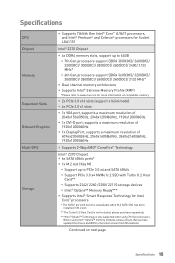
...™ i3/i5/i7 processors, and Intel® Pentium® and Celeron® processors for Socket LGA1151 Intel® Z270 Chipset y 4x DDR4 memory slots, support up to the latest version from MSI website. y 2x PCIe 3.0 x16 slots (support x16/x4 mode) y 4x PCIe 3.0 x1 slots y 1x VGA port, .... ***Intel® Optane™ Technology is only supported when using Intel® Optane™ memory modules, please ensure that you have updated the drivers and BIOS to PCIe 3.0 x4 and SATA 6Gb/s ƒ Support PCIe 3.0 x4 NVMe U.2 SSD with Turbo U.2 Host Card** ƒ Supports 2242/ 2260 /2280/ ...
...™ i3/i5/i7 processors, and Intel® Pentium® and Celeron® processors for Socket LGA1151 Intel® Z270 Chipset y 4x DDR4 memory slots, support up to the latest version from MSI website. y 2x PCIe 3.0 x16 slots (support x16/x4 mode) y 4x PCIe 3.0 x1 slots y 1x VGA port, .... ***Intel® Optane™ Technology is only supported when using Intel® Optane™ memory modules, please ensure that you have updated the drivers and BIOS to PCIe 3.0 x4 and SATA 6Gb/s ƒ Support PCIe 3.0 x4 NVMe U.2 SSD with Turbo U.2 Host Card** ƒ Supports 2242/ 2260 /2280/ ...

User Manual
Page 17
... Factor y 12.0 in . (30.5 cm x 22.5 cm) y 1x 128 Mb flash y UEFI AMI BIOS y ACPI 5.0, PnP 1.0a, SM BIOS 2.8 y Multi-language y Drivers y SUPER CHARGER y FAST BOOT y COMMAND CENTER y LIVE UPDATE 6 y MSI SMART TOOL y X-BOOST y MYSTIC LIGHT y RAMDISK y NETWORK MANAGER y CPU-Z MSI GAMING y Intel® Extreme Tuning Utility y Norton™ Internet Security Solution y Google Chrome...
... Factor y 12.0 in . (30.5 cm x 22.5 cm) y 1x 128 Mb flash y UEFI AMI BIOS y ACPI 5.0, PnP 1.0a, SM BIOS 2.8 y Multi-language y Drivers y SUPER CHARGER y FAST BOOT y COMMAND CENTER y LIVE UPDATE 6 y MSI SMART TOOL y X-BOOST y MYSTIC LIGHT y RAMDISK y NETWORK MANAGER y CPU-Z MSI GAMING y Intel® Extreme Tuning Utility y Norton™ Internet Security Solution y Google Chrome...
User Manual
Page 24
..., JFP2 JLPT1 JTPM1 JUSB1~2 JUSB3~4 M2_1 PCI_E1~6 SATA1~6 Port Type Fan Connectors Power Connectors LGA1151 CPU Socket DIMM Slots Front Audio Connector Clear CMOS (Reset BIOS) Jumper Chassis Intrusion Connector Serial Port Connector Front Panel Connectors Parallel Port Connector TPM Module Connector USB 2.0 Connectors USB 3.1 Gen1 Connectors M.2 Slot (Key M) PCIe Expansion...
..., JFP2 JLPT1 JTPM1 JUSB1~2 JUSB3~4 M2_1 PCI_E1~6 SATA1~6 Port Type Fan Connectors Power Connectors LGA1151 CPU Socket DIMM Slots Front Audio Connector Clear CMOS (Reset BIOS) Jumper Chassis Intrusion Connector Serial Port Connector Front Panel Connectors Parallel Port Connector TPM Module Connector USB 2.0 Connectors USB 3.1 Gen1 Connectors M.2 Slot (Key M) PCIe Expansion...

User Manual
Page 32
... connectors provide constant 12V output and adjust fan speed with speed control signal. When you to adjust fan speed in relation to a fan connector in BIOS > HARDWARE MONITOR. Pin definition of fan connectors PWM Mode pin definition 1 Ground 2 +12V 3 Sense 4 Speed Control Signal DC Mode pin definition 1 Ground 2 Voltage Control 3 Sense...
... connectors provide constant 12V output and adjust fan speed with speed control signal. When you to adjust fan speed in relation to a fan connector in BIOS > HARDWARE MONITOR. Pin definition of fan connectors PWM Mode pin definition 1 Ground 2 +12V 3 Sense 4 Speed Control Signal DC Mode pin definition 1 Ground 2 Voltage Control 3 Sense...

User Manual
Page 33
...Head Phone Detection JCI1: Chassis Intrusion Connector This connector allows you to connect the chassis intrusion switch cable. Set Chassis Intrusion to BIOS > SETTINGS > Security > Chassis Intrusion Configuration. 4. Press F10 to save and exit and then press the Enter key to...(default) Trigger the chassis intrusion event Using chassis intrusion detector 1. Go to Reset. 3. Go to Enabled. 5. Set Chassis Intrusion to BIOS > SETTINGS > Security > Chassis Intrusion Configuration. 2. Close the chassis cover. 3. JAUD1: Front Audio Connector This connector allows you to connect...
...Head Phone Detection JCI1: Chassis Intrusion Connector This connector allows you to connect the chassis intrusion switch cable. Set Chassis Intrusion to BIOS > SETTINGS > Security > Chassis Intrusion Configuration. 4. Press F10 to save and exit and then press the Enter key to...(default) Trigger the chassis intrusion event Using chassis intrusion detector 1. Go to Reset. 3. Go to Enabled. 5. Set Chassis Intrusion to BIOS > SETTINGS > Security > Chassis Intrusion Configuration. 2. Close the chassis cover. 3. JAUD1: Front Audio Connector This connector allows you to connect...
User Manual
Page 34
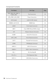
Keep Data (default) Clear CMOS/ Reset BIOS Resetting BIOS to clear the CMOS memory. Use a jumper cap to short JBAT1 for more details and usages. 2 14 1 13 1 LPC Clock 2 3V Standby power 3 LPC Reset 4 5 ... 8 9 LPC address & data pin2 10 5V Power No Pin 11 LPC address & data pin3 12 13 LPC Frame 14 Ground Ground JBAT1: Clear CMOS (Reset BIOS) Jumper There is CMOS memory onboard that is for TPM (Trusted Platform Module). Plug the power cord and power on the motherboard to the TPM...
Keep Data (default) Clear CMOS/ Reset BIOS Resetting BIOS to clear the CMOS memory. Use a jumper cap to short JBAT1 for more details and usages. 2 14 1 13 1 LPC Clock 2 3V Standby power 3 LPC Reset 4 5 ... 8 9 LPC address & data pin2 10 5V Power No Pin 11 LPC address & data pin3 12 13 LPC Frame 14 Ground Ground JBAT1: Clear CMOS (Reset BIOS) Jumper There is CMOS memory onboard that is for TPM (Trusted Platform Module). Plug the power cord and power on the motherboard to the TPM...
User Manual
Page 36
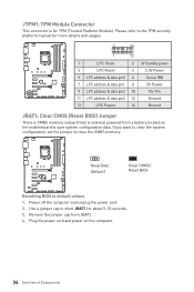
... button and choose OK. Click on the screen during the boot process. y The pictures in normal conditions. The system will reboot and enter BIOS setup directly. Select between Advanced mode and EZ mode F8: Load Overclocking Profile F9: Save Overclocking Profile F10: Save Change and Reset* F12:...and may be for reference only. You should be slightly different from the product you are familiar with BIOS. y Press Delete key, when the Press DEL key to enter Setup Menu, F11 to avoid possible system damage or failure booting unless you purchased. y Use MSI FAST BOOT application.
... button and choose OK. Click on the screen during the boot process. y The pictures in normal conditions. The system will reboot and enter BIOS setup directly. Select between Advanced mode and EZ mode F8: Load Overclocking Profile F9: Save Overclocking Profile F10: Save Change and Reset* F12:...and may be for reference only. You should be slightly different from the product you are familiar with BIOS. y Press Delete key, when the Press DEL key to enter Setup Menu, F11 to avoid possible system damage or failure booting unless you purchased. y Use MSI FAST BOOT application.
User Manual
Page 37
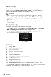
... the USB flash drive that matches your motherboard model from MSI website. Select a BIOS file to the Clear CMOS jumper section for resetting BIOS. Updating the BIOS with M-FLASH Before updating: Please download the latest BIOS file that contains the update file into the USB flash ...properly. Select the M-FLASH tab and click on icon to start updating BIOS. 6. Updating BIOS: 1. Install and launch MSI LIVE UPDATE 6. 2. Updating BIOS: 1. Click Next and choose In Windows mode. Updating BIOS Updating BIOS with Live Update 6 Before updating: Make sure the LAN driver is already...
... the USB flash drive that matches your motherboard model from MSI website. Select a BIOS file to the Clear CMOS jumper section for resetting BIOS. Updating the BIOS with M-FLASH Before updating: Please download the latest BIOS file that contains the update file into the USB flash ...properly. Select the M-FLASH tab and click on icon to start updating BIOS. 6. Updating BIOS: 1. Install and launch MSI LIVE UPDATE 6. 2. Updating BIOS: 1. Click Next and choose In Windows mode. Updating BIOS Updating BIOS with Live Update 6 Before updating: Make sure the LAN driver is already...

User Manual
Page 38
...System information - shows the CPU/ DDR speed, CPU/ MB temperature, MB/ CPU type, memory size, CPU/ DDR voltage, BIOS version and build date. 38 BIOS Setup XMP switch Setup Mode switch Screenshot Search Language System information OC GENIE 4 switch Boot device priority bar Information display M-Flash Favorites ... to keep the optimal performance and system stability after activating the OC GENIE 4 function. To configure the advanced BIOS settings, please enter the Advanced Mode by BIOS item name, enter the item name to find the item listing. click on this tab or the Ctrl+F ...
...System information - shows the CPU/ DDR speed, CPU/ MB temperature, MB/ CPU type, memory size, CPU/ DDR voltage, BIOS version and build date. 38 BIOS Setup XMP switch Setup Mode switch Screenshot Search Language System information OC GENIE 4 switch Boot device priority bar Information display M-Flash Favorites ... to keep the optimal performance and system stability after activating the OC GENIE 4 function. To configure the advanced BIOS settings, please enter the Advanced Mode by BIOS item name, enter the item name to find the item listing. click on this tab or the Ctrl+F ...

User Manual
Page 39
... 39 enable or disable the LAN Option ROM, M.2 Genie, HD audio controller, AHCI, RAID, CPU Fan Fail Warning Control and BIOS Log Review by percentage. Choose a favorite page and click on left to change the boot priority. Choose Delete and click on favorite page (Favorite 1~5) 2. ... the M-Flash menu that allows you can move the device icons to right. SETTINGS, OC...,etc) as the BIOS home page. ƒ Favorite1~5 - Move the mouse over a BIOS item not only on BIOS menu but also on their respective button. click on this button to display the Hardware Monitor menu that provides...
... 39 enable or disable the LAN Option ROM, M.2 Genie, HD audio controller, AHCI, RAID, CPU Fan Fail Warning Control and BIOS Log Review by percentage. Choose a favorite page and click on left to change the boot priority. Choose Delete and click on favorite page (Favorite 1~5) 2. ... the M-Flash menu that allows you can move the device icons to right. SETTINGS, OC...,etc) as the BIOS home page. ƒ Favorite1~5 - Move the mouse over a BIOS item not only on BIOS menu but also on their respective button. click on this button to display the Hardware Monitor menu that provides...

User Manual
Page 40
...and boot devices. ƒ OC - XMP switch Setup Mode switch OC GENIE 4 switch Screenshot Search Language System information Boot device priority bar BIOS menu selection BIOS menu selection Menu display y OC GENIE 4 switch/ XMP switch/ Setup Mode switch/ Screenshot/ Language/ System information/ Boot device priority bar...y Menu display - Advanced Mode Press Setup Mode switch or F7 function key can switch between EZ Mode and Advanced Mode in BIOS setup. allows you to adjust the frequency and voltage. allows you to the descriptions of EZ Mode Overview section. please refer ...
...and boot devices. ƒ OC - XMP switch Setup Mode switch OC GENIE 4 switch Screenshot Search Language System information Boot device priority bar BIOS menu selection BIOS menu selection Menu display y OC GENIE 4 switch/ XMP switch/ Setup Mode switch/ Screenshot/ Language/ System information/ Boot device priority bar...y Menu display - Advanced Mode Press Setup Mode switch or F7 function key can switch between EZ Mode and Advanced Mode in BIOS setup. allows you to adjust the frequency and voltage. allows you to the descriptions of EZ Mode Overview section. please refer ...

User Manual
Page 41
...timer. through Dec. Use tab key to switch between date elements. f System Information Shows detailed system information, including CPU type, BIOS version, and Memory (read only). f DMI Information Shows system information, desktop Board Information and chassis Information. (Read only). The year ...can be adjusted by BIOS. The time format is . f SATA PortX/ M2_X Shows the information of the device and motherboard. Use tab key to 31 ...
...timer. through Dec. Use tab key to switch between date elements. f System Information Shows detailed system information, including CPU type, BIOS version, and Memory (read only). f DMI Information Shows system information, desktop Board Information and chassis Information. (Read only). The year ...can be adjusted by BIOS. The time format is . f SATA PortX/ M2_X Shows the information of the device and motherboard. Use tab key to 31 ...
User Manual
Page 42
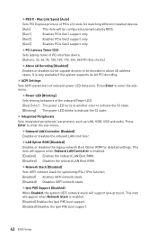
...will appear when Network Stack is enabled. [Enabled] Enables the Ipv4 PXE boot support. [Disabled] Disables the Ipv4 PXE boot support. 42 BIOS Setup fPower LED [Blinking] Sets shining behaviors of PCIe x16 slots for matching different installed devices. [Auto] This item will appear when ...color to indicate the S3 state. [Blinking] The power LED blinks to enter the submenu. fPEG X - Press Enter to be configured automatically by BIOS. [Gen1] Enables PCIe Gen1 support only. [Gen2] Enables PCIe Gen2 support only. [Gen3] Enables PCIe Gen3 support only. fPCI Latency Timer [32...
...will appear when Network Stack is enabled. [Enabled] Enables the Ipv4 PXE boot support. [Disabled] Disables the Ipv4 PXE boot support. 42 BIOS Setup fPower LED [Blinking] Sets shining behaviors of PCIe x16 slots for matching different installed devices. [Auto] This item will appear when ...color to indicate the S3 state. [Blinking] The power LED blinks to enter the submenu. fPEG X - Press Enter to be configured automatically by BIOS. [Gen1] Enables PCIe Gen1 support only. [Gen2] Enables PCIe Gen2 support only. [Gen3] Enables PCIe Gen3 support only. fPCI Latency Timer [32...
User Manual
Page 43
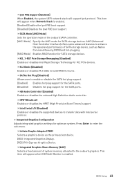
... Mode] Enables RAID function for SATA storage devices. fM2_1-RST Pcie Storage Remapping [Disabled] Enables or disables Intel Rapid Storage Technology for SATA storage devices. BIOS Setup 43 Press Enter to the onboard graphics. AHCI (Advanced Host Controller Interface) offers some advanced features to enable or disable the SATA hot plug...
... Mode] Enables RAID function for SATA storage devices. fM2_1-RST Pcie Storage Remapping [Disabled] Enables or disables Intel Rapid Storage Technology for SATA storage devices. BIOS Setup 43 Press Enter to the onboard graphics. AHCI (Advanced Host Controller Interface) offers some advanced features to enable or disable the SATA hot plug...
User Manual
Page 44
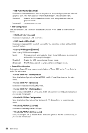
...COM ports. Press Enter to enter the submenu. fUSB Controller [Enabled] Enables or disables all USB controller. Press Enter to Auto, BIOS will optimize the IRQ automatically or you can set it manually. fSerial (COM) Port 0 Configuration Sets detailed configuration of ... fIGD Multi-Monitor [Disabled] Enables or disables the multi-screen output from integrated graphics and external graphics card. Press Enter to Auto, BIOS will be unavailable under legacy mode. fParallel (LPT) Port [Enabled] Enables or disables parallel(LPT) port. fLegacy USB Support [Enabled...
...COM ports. Press Enter to enter the submenu. fUSB Controller [Enabled] Enables or disables all USB controller. Press Enter to Auto, BIOS will optimize the IRQ automatically or you can set it manually. fSerial (COM) Port 0 Configuration Sets detailed configuration of ... fIGD Multi-Monitor [Disabled] Enables or disables the multi-screen output from integrated graphics and external graphics card. Press Enter to Auto, BIOS will be unavailable under legacy mode. fParallel (LPT) Port [Enabled] Enables or disables parallel(LPT) port. fLegacy USB Support [Enabled...
User Manual
Page 45
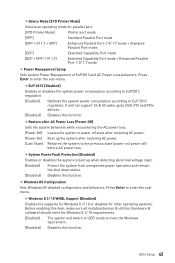
... boot up when detecting abnormal voltage input. [Enabled] Protect the system from unexpected power operation and remain the shut down status. [Disabled] Disables this function. BIOS Setup 45 Press Enter to EuP 2013 regulation. fDevice Mode [STD Printer Mode] Selects an operating mode for other operating systems. Before enabling this item...
... boot up when detecting abnormal voltage input. [Enabled] Protect the system from unexpected power operation and remain the shut down status. [Disabled] Disables this function. BIOS Setup 45 Press Enter to EuP 2013 regulation. fDevice Mode [STD Printer Mode] Selects an operating mode for other operating systems. Before enabling this item...
User Manual
Page 46
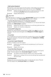
...sets to speed up system boot time which is faster than the boot time of Fast Boot. [Enabled] Enables the MSI Fast Boot function to Custom. 46 BIOS Setup fSecure Boot Support [Disabled] Enables or disables secure boot support. [Enabled] Enables the secure boot function and ...allow you can use MSI FAST BOOT application to enter the sub-menu. Press to prevent the unauthorized accessing. fKey Management Manages ...
...sets to speed up system boot time which is faster than the boot time of Fast Boot. [Enabled] Enables the MSI Fast Boot function to Custom. 46 BIOS Setup fSecure Boot Support [Disabled] Enables or disables secure boot support. [Enabled] Enables the secure boot function and ...allow you can use MSI FAST BOOT application to enter the sub-menu. Press to prevent the unauthorized accessing. fKey Management Manages ...
User Manual
Page 47
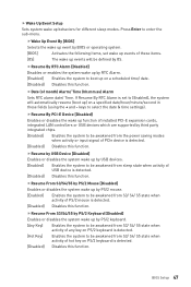
... (using the + and - Press Enter to select the date & time settings). keys to enter the sub-menu. BIOS Setup 47 fWake Up Event By [BIOS] Selects the wake up event by BIOS or operating system. [BIOS] Activates the following items, set to be awakened from the power saving modes when activity or input signal...
... (using the + and - Press Enter to select the date & time settings). keys to enter the sub-menu. BIOS Setup 47 fWake Up Event By [BIOS] Selects the wake up event by BIOS or operating system. [BIOS] Activates the following items, set to be awakened from the power saving modes when activity or input signal...


