User Guide
Page 2
... X58 Pro-E Date March 2009 Technical Support If a problem arises with your system and no guarantee is given as to make changes without notice. Trademarks All trademarks are under continual improvement and we reserve the right to the correctness of purchase or local distributor. Revision History Revision V3.1 Revision History First release for FAQ, technical guide, BIOS updates, driver updates...
... X58 Pro-E Date March 2009 Technical Support If a problem arises with your system and no guarantee is given as to make changes without notice. Trademarks All trademarks are under continual improvement and we reserve the right to the correctness of purchase or local distributor. Revision History Revision V3.1 Revision History First release for FAQ, technical guide, BIOS updates, driver updates...
User Guide
Page 8
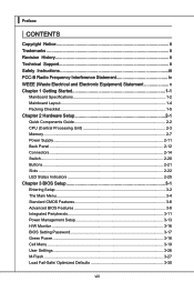
... Started 1-1 Mainboard Specifications 1-2 Mainboard Layout 1-4 Packing Checklist 1-5 Chapter 2 Hardware Setup 2-1 Quick Components Guide 2-2 CPU (Central Processing Unit 2-3 Memory 2-7 Power Supply 2-11 Back Panel 2-12 Connectors 2-14 Switch 2-20 Buttons 2-21 Slots 2-22 LED Status Indicators 2-25 Chapter 3 BIOS Setup 3-1 Entering Setup 3-2 The Main Menu 3-4 Standard CMOS Features 3-6 Advanced BIOS Features 3-8 Integrated Peripherals 3-11 Power Management Setup 3-13 H/W Monitor 3-16 BIOS Setting Password 3-17 Green Power 3-18 Cell Menu 3-19 User Settings 3-26 M-Flash...
... Started 1-1 Mainboard Specifications 1-2 Mainboard Layout 1-4 Packing Checklist 1-5 Chapter 2 Hardware Setup 2-1 Quick Components Guide 2-2 CPU (Central Processing Unit 2-3 Memory 2-7 Power Supply 2-11 Back Panel 2-12 Connectors 2-14 Switch 2-20 Buttons 2-21 Slots 2-22 LED Status Indicators 2-25 Chapter 3 BIOS Setup 3-1 Entering Setup 3-2 The Main Menu 3-4 Standard CMOS Features 3-6 Advanced BIOS Features 3-8 Integrated Peripherals 3-11 Power Management Setup 3-13 H/W Monitor 3-16 BIOS Setting Password 3-17 Green Power 3-18 Cell Menu 3-19 User Settings 3-26 M-Flash...

User Guide
Page 12
... compatible components, please visit http://www.msi.com/index.php?func=testreport) LAN ■ Supports PCIE LAN 10/100/1000 Fast Ethernet by Realtek 8111C Audio ■ Chip integrated by Realtek® ALC889 ■ Flexible 8-channel audio with jack sensing ■ Compliant with Azalia 1.0 Spec IDE ■ 1 IDE port by JMicron® JMB363 ■ Supports Ultra DMA 66/100/133 mode ■ Supports PIO, Bus Master operation mode SATA ■ 6 SATA ports...
... compatible components, please visit http://www.msi.com/index.php?func=testreport) LAN ■ Supports PCIE LAN 10/100/1000 Fast Ethernet by Realtek 8111C Audio ■ Chip integrated by Realtek® ALC889 ■ Flexible 8-channel audio with jack sensing ■ Compliant with Azalia 1.0 Spec IDE ■ 1 IDE port by JMicron® JMB363 ■ Supports Ultra DMA 66/100/133 mode ■ Supports PIO, Bus Master operation mode SATA ■ 6 SATA ports...

User Guide
Page 13
... 2.0 Ports - 1 LAN jack - 6 flexible audio jacks ■ On-Board Connectors - 3 USB 2.0 connectors - 1 1394 connector - 1 chassis intrusion connector - 1 serial port connector - 1 TPM Module connector - 1 CD-In connector - 1 front audio connector - 1 Clear CMOS button - 1 Power button - 1 Reset button TPM (optional) ■ - Supports TPM Slots ■ 2 PCI Express gen2 x16 slots (PCI_E2, PCI_E4) ■ 1 PCI Express x16 slot supports up to PCI Express gen2 x4 speed (PCI_E5) ■ 2 PCI Express gen1 x1 slots ■ 2 PCI slots, support 3.3V/ 5V PCI bus Interface Form Factor ■ ATX...
... 2.0 Ports - 1 LAN jack - 6 flexible audio jacks ■ On-Board Connectors - 3 USB 2.0 connectors - 1 1394 connector - 1 chassis intrusion connector - 1 serial port connector - 1 TPM Module connector - 1 CD-In connector - 1 front audio connector - 1 Clear CMOS button - 1 Power button - 1 Reset button TPM (optional) ■ - Supports TPM Slots ■ 2 PCI Express gen2 x16 slots (PCI_E2, PCI_E4) ■ 1 PCI Express x16 slot supports up to PCI Express gen2 x4 speed (PCI_E5) ■ 2 PCI Express gen1 x1 slots ■ 2 PCI slots, support 3.3V/ 5V PCI bus Interface Form Factor ■ ATX...
User Guide
Page 30
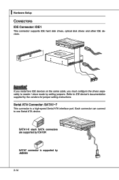
Refer to one Serial ATA device. Each connector can connect to IDE device's documentation supplied by JMB363 2-14 ▍ Hardware Setup Connectors IDE Connector: IDE1 This connector supports IDE hard disk drives, optical disk drives and other IDE devices. Serial ATA Connector: SATA1~7 This connector is supported by the vendors for jumper setting instructions. Fl opMpySDI FlopMpySDIFlopMpySDI Kdkldkddfkkakfskkdskkdakaddfdddffdfkad-dkdffdlkdddjdafddsddjfdddfkadfasdfdddffdfadasfsadfddsddadasdasddsdafsddadsdddfdsadddfffaffsfsdasfdfffdf K dk ldkddfkkakfskkdskkdakaddfdddffdfka-...
Refer to one Serial ATA device. Each connector can connect to IDE device's documentation supplied by JMB363 2-14 ▍ Hardware Setup Connectors IDE Connector: IDE1 This connector supports IDE hard disk drives, optical disk drives and other IDE devices. Serial ATA Connector: SATA1~7 This connector is supported by the vendors for jumper setting instructions. Fl opMpySDI FlopMpySDIFlopMpySDI Kdkldkddfkkakfskkdskkdakaddfdddffdfkad-dkdffdlkdddjdafddsddjfdddfkadfasdfdddffdfadasfsadfddsddadasdasddsdafsddadsdddfdsadddfffaffsfsdasfdfffdf K dk ldkddfkkakfskkdskkdakaddfdddffdfka-...

User Guide
Page 31
....+6.-8.+ JFP2 1.G3.rSo5uu.Psn7opd.NweonedrPLLinEEDD Fan Power Connectors: CPUFAN1, SYSFAN1~3 The fan power connectors support system cooling fan with speed sensor to the +12V; MS-7522 Important • Please do not fold the Serial ATA cable into 90-degree angle. If the mainboard has a System Hardware Monitor chipset on-board, you must use the Intel default SATA connectors (SATA1~6) first. Otherwise, data loss may select how percentage of the CPU fan control.
....+6.-8.+ JFP2 1.G3.rSo5uu.Psn7opd.NweonedrPLLinEEDD Fan Power Connectors: CPUFAN1, SYSFAN1~3 The fan power connectors support system cooling fan with speed sensor to the +12V; MS-7522 Important • Please do not fold the Serial ATA cable into 90-degree angle. If the mainboard has a System Hardware Monitor chipset on-board, you must use the Intel default SATA connectors (SATA1~6) first. Otherwise, data loss may select how percentage of the CPU fan control.

User Guide
Page 34
... TPM Module connector: JTPM1 This connector connects to the TPM security platform manual for more details and usages. 2.34V.36S..3tS8aVe.n15Prd0iVaob1.NlwyP2I1o.eRopG4rwoPQ.rwGeionreurornudnd 1.L3P.L5CP.LCC7P.loLRC9cP.eLka1CsPd1e1ad.CtL3drPea.dLsdCrPsedasCr&edsFdsd&sraraedt&amsasdpteaa&intpa0dinap1tian2pin3 2-18 Please refer to a TPM (Trusted Platform Module) module (optional). ▍ Hardware Setup Serial Port Connector: JCOM1 This connector is a 16550A high speed communication port that sends...
... TPM Module connector: JTPM1 This connector connects to the TPM security platform manual for more details and usages. 2.34V.36S..3tS8aVe.n15Prd0iVaob1.NlwyP2I1o.eRopG4rwoPQ.rwGeionreurornudnd 1.L3P.L5CP.LCC7P.loLRC9cP.eLka1CsPd1e1ad.CtL3drPea.dLsdCrPsedasCr&edsFdsd&sraraedt&amsasdpteaa&intpa0dinap1tian2pin3 2-18 Please refer to a TPM (Trusted Platform Module) module (optional). ▍ Hardware Setup Serial Port Connector: JCOM1 This connector is a 16550A high speed communication port that sends...

User Guide
Page 37
... set the computer's function. Press the button to reset the system. MS-7522 Buttons The motherboard provides the following button for you want to clear the system configuration, use of button. Clear CMOS Button: CLR_CMOS1 There is a CMOS RAM on board that you power-on the system, and the light will light when the system is turned on or turn -off the system. Important Make sure that has a power supply from external battery to reset...
... set the computer's function. Press the button to reset the system. MS-7522 Buttons The motherboard provides the following button for you want to clear the system configuration, use of button. Clear CMOS Button: CLR_CMOS1 There is a CMOS RAM on board that you power-on the system, and the light will light when the system is turned on or turn -off the system. Important Make sure that has a power supply from external battery to reset...

User Guide
Page 38
... scalable gaming platform ever. CrossFireXTM Video Link cable 2-22 It allows you the ability to scale your system's graphics capabilities. The motherboard can auto detect the CrossFireXTM mode by software, therefore you to improve system performance. PCI Express x16 Slot PCI Express x1 Slot ATI CrossFireXTM (Multi-GPU) Technology ATI CrossFireXTM is required to connect the golden fingers on the graphics card installed in the third PCIE x16 (PCI_E4...
... scalable gaming platform ever. CrossFireXTM Video Link cable 2-22 It allows you the ability to scale your system's graphics capabilities. The motherboard can auto detect the CrossFireXTM mode by software, therefore you to improve system performance. PCI Express x16 Slot PCI Express x1 Slot ATI CrossFireXTM (Multi-GPU) Technology ATI CrossFireXTM is required to connect the golden fingers on the graphics card installed in the third PCIE x16 (PCI_E4...
User Guide
Page 40
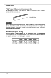
... PCI slot supports LAN card, SCSI card, USB card, and other add-on cards that comply with PCI specifications. 32-bit PCI Slot Important When adding or removing expansion cards, make sure that you unplug the power supply first. The PCI IRQ pins are hardware lines over which devices can send interrupt signals to the microprocessor. PCI Interrupt Request Routing The IRQ, acronym of interrupt request line and pronounced I-R-Q, are typically connected to configure...
... PCI slot supports LAN card, SCSI card, USB card, and other add-on cards that comply with PCI specifications. 32-bit PCI Slot Important When adding or removing expansion cards, make sure that you unplug the power supply first. The PCI IRQ pins are hardware lines over which devices can send interrupt signals to the microprocessor. PCI Interrupt Request Routing The IRQ, acronym of interrupt request line and pronounced I-R-Q, are typically connected to configure...

User Guide
Page 49
... LBA mode disabled. ▶ DMA Mode Select DMA Mode. ▶ Hard Disk S.M.A.R.T. Important SATA1~7, IDE Primary Master/ Slave & E-SATA1 are appearing when you to activate the S.M.A.R.T. (Self-Monitoring Analysis & Reporting Technology) capability for the hard disks. This sub-menu shows the CPU information, BIOS version and memory status of your disk status to predict hard disk failure. MS-7522 ▶ Device / Vendor / Size It will showing the device information that you connected to the SATA connector...
... LBA mode disabled. ▶ DMA Mode Select DMA Mode. ▶ Hard Disk S.M.A.R.T. Important SATA1~7, IDE Primary Master/ Slave & E-SATA1 are appearing when you to activate the S.M.A.R.T. (Self-Monitoring Analysis & Reporting Technology) capability for the hard disks. This sub-menu shows the CPU information, BIOS version and memory status of your disk status to predict hard disk failure. MS-7522 ▶ Device / Vendor / Size It will showing the device information that you connected to the SATA connector...
User Guide
Page 50
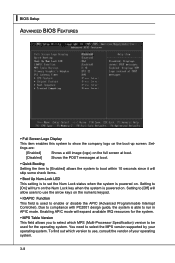
... powered on the boot-up screen. To find out which MPS (Multi-Processor Specification) version to be used to run in APIC mode. ▍ BIOS Setup Advanced BIOS Features ▶ Full Screen Logo Display This item enables this system to show the company logo on . You need to select the MPS version supported by your operating system. 3-8 Settings are: [Enabled] Shows a still image (logo) on the full screen at boot. [Disabled...
... powered on the boot-up screen. To find out which MPS (Multi-Processor Specification) version to be used to run in APIC mode. ▍ BIOS Setup Advanced BIOS Features ▶ Full Screen Logo Display This item enables this system to show the company logo on . You need to select the MPS version supported by your operating system. 3-8 Settings are: [Enabled] Shows a still image (logo) on the full screen at boot. [Disabled...

User Guide
Page 51
... Technology; • Chipset: An Intel® Chipset that supports HT Technology; • BIOS: A BIOS that supports HT Technology and has it cannot. When set the item to higher values. ▶ CPU Feature Press to execute the instructions. For better PCI performance, you disable the function, the processor will use only one core to enter the sub-menu and the following platform Components: • CPU: An Intel® Pentium® 4 Processor with a supporting...
... Technology; • Chipset: An Intel® Chipset that supports HT Technology; • BIOS: A BIOS that supports HT Technology and has it cannot. When set the item to higher values. ▶ CPU Feature Press to execute the instructions. For better PCI performance, you disable the function, the processor will use only one core to enter the sub-menu and the following platform Components: • CPU: An Intel® Pentium® 4 Processor with a supporting...

User Guide
Page 54
▍ BIOS Setup ▶ PCI IDE BusMaster This item allows you to enable/ disable BIOS to used PCI busmastering for reading/ writing to IDE drives. ▶ On-Chip SATA Controller These items allow users to enable or disable the SATA controller. ▶ RAID Mode This item allows you to configure RAID mode for onboard SATA devices. ▶ I/O Devices Press to enter the sub-menu and the following screen appears: ▶ COM Port 1 Select an address and corresponding interrupt for the first serial port. 3-12
▍ BIOS Setup ▶ PCI IDE BusMaster This item allows you to enable/ disable BIOS to used PCI busmastering for reading/ writing to IDE drives. ▶ On-Chip SATA Controller These items allow users to enable or disable the SATA controller. ▶ RAID Mode This item allows you to configure RAID mode for onboard SATA devices. ▶ I/O Devices Press to enter the sub-menu and the following screen appears: ▶ COM Port 1 Select an address and corresponding interrupt for the first serial port. 3-12

User Guide
Page 55
.... The information stored in memory will reboot after a power failure or interrupt occurs. If your operating system supports ACPI, such as Windows 2000/XP, select [Enabled]. ▶ ACPI Standby State This item specifies the power saving modes for ACPI function. Settings are : [S1] The S1 sleep mode is saved to enter the Standby mode in the power off to activate the ACPI (Advanced Configuration and Power Management Interface) Function. If...
.... The information stored in memory will reboot after a power failure or interrupt occurs. If your operating system supports ACPI, such as Windows 2000/XP, select [Enabled]. ▶ ACPI Standby State This item specifies the power saving modes for ACPI function. Settings are : [S1] The S1 sleep mode is saved to enter the Standby mode in the power off to activate the ACPI (Advanced Configuration and Power Management Interface) Function. If...

User Guide
Page 56
... By Setting to [BIOS] activates the following fields, and use the following fields to set the wake up the system from S3 (Suspend to RAM) sleep state. ▶ Resume From S3 By PS/2 Keyboard This setting determines whether the system will be awakened from the power saving modes through any event on PME (Power Management Event). ▶ Resume By PCI-E Device When set to [Enabled], the...
... By Setting to [BIOS] activates the following fields, and use the following fields to set the wake up the system from S3 (Suspend to RAM) sleep state. ▶ Resume From S3 By PS/2 Keyboard This setting determines whether the system will be awakened from the power saving modes through any event on PME (Power Management Event). ▶ Resume By PCI-E Device When set to [Enabled], the...

User Guide
Page 58
..., the smart fan function will automatically return to [Enabled] later. ▶ CPU Smart Fan Target The mainboard provides the Smart Fan function which can enable a fan target value here. It provides several sections to speed up for cooling down automatically. ▶ SYS FAN1/2 Control This item allows users to [Reset]. ▍ BIOS Setup H/W Monitor ▶ Chassis Intrusion The field enables or disables the feature of the monitored hardware devices/components such as CPU voltage, temperatures and...
..., the smart fan function will automatically return to [Enabled] later. ▶ CPU Smart Fan Target The mainboard provides the Smart Fan function which can enable a fan target value here. It provides several sections to speed up for cooling down automatically. ▶ SYS FAN1/2 Control This item allows users to [Reset]. ▍ BIOS Setup H/W Monitor ▶ Chassis Intrusion The field enables or disables the feature of the monitored hardware devices/components such as CPU voltage, temperatures and...

User Guide
Page 69
... option is for USB drive only. 3-27 It only supports particular file name, which is the official BIOS file name from official website and must be saved in the root directory of the USB/ Storage drive. Update BIOS ROM chip data from selected file, which is download from us. [Boot] After allocated particular BIOS file, system will skip MB ROM chip data and boot with thisparticular BIOS inside USB drive (FAT/ FAT32 format only). [Disabled] Disable M-Flash function. [BIOS Update] Flash BIOS...
... option is for USB drive only. 3-27 It only supports particular file name, which is the official BIOS file name from official website and must be saved in the root directory of the USB/ Storage drive. Update BIOS ROM chip data from selected file, which is download from us. [Boot] After allocated particular BIOS file, system will skip MB ROM chip data and boot with thisparticular BIOS inside USB drive (FAT/ FAT32 format only). [Disabled] Disable M-Flash function. [BIOS Update] Flash BIOS...
User Guide
Page 105
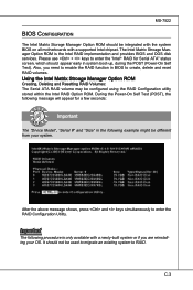
... a supported Intel chipset. During the Power-On Self Test (POST), the following message will appear for Serial ATA" status screen, which should appear early in the following procedure is the Intel RAID implementation and provides BIOS and DOS disk services. C-3 Please use + keys to enter the RAID Configuration Utility. Also, you are reinstalling your system. Using the Intel Matrix Stroage Manager Option ROM Creating, Deleting and Resetting RAID Volumes: The Serial ATA RAID...
... a supported Intel chipset. During the Power-On Self Test (POST), the following message will appear for Serial ATA" status screen, which should appear early in the following procedure is the Intel RAID implementation and provides BIOS and DOS disk services. C-3 Please use + keys to enter the RAID Configuration Utility. Also, you are reinstalling your system. Using the Intel Matrix Stroage Manager Option ROM Creating, Deleting and Resetting RAID Volumes: The Serial ATA RAID...
User Guide
Page 112
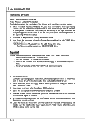
... created in your system". Insert the MSI CD into the A: drive. Click the "Browse CD" on "Load Driver" button to install a third party SCSI or RAID driver. 5. dows setup should be shown a list of Windows setup. 2. ▍ Intel ICH10R SATA RAID Installing Driver Install Driver in \\IDE\Intel\ICH10R\Floppy to a formatted floppy diskette. 4. For Windows Vista you can use the USB floppy drive only. Select the appropriate Intel RAID controller and press ENTER. 8. You should continue. 10. Leave...
... created in your system". Insert the MSI CD into the A: drive. Click the "Browse CD" on "Load Driver" button to install a third party SCSI or RAID driver. 5. dows setup should be shown a list of Windows setup. 2. ▍ Intel ICH10R SATA RAID Installing Driver Install Driver in \\IDE\Intel\ICH10R\Floppy to a formatted floppy diskette. 4. For Windows Vista you can use the USB floppy drive only. Select the appropriate Intel RAID controller and press ENTER. 8. You should continue. 10. Leave...


