
User Guide
Page 2
... obtained from the user's manual, please contact your place of Microsoft Corporation. Trademarks All trademarks are the properties of M ICRO-STAR INTERNATIONAL. PS/2 and OS®/2 are registered trademarks of International Business Machines Corporation. Alternatively, please try the following help resources for FAQ, technical guide, BIOS updates, driver updates, and other countries. Visit the MSI website at http://support.msi.com.tw/. AMD...
... obtained from the user's manual, please contact your place of Microsoft Corporation. Trademarks All trademarks are the properties of M ICRO-STAR INTERNATIONAL. PS/2 and OS®/2 are registered trademarks of International Business Machines Corporation. Alternatively, please try the following help resources for FAQ, technical guide, BIOS updates, driver updates, and other countries. Visit the MSI website at http://support.msi.com.tw/. AMD...

User Guide
Page 8
... Installing DDRII Modules 2-6 Power Supply ...2-7 SSI 24-Pin System Power Connector: JPWR1 2-7 Connectors ...2-8 Serial Attached SCSI Connectors: SAS1/SAS2 2-8 Serial ATA Connectors: SATA1/SATA2 2-9 Front USB Connectors: JUSB3001, JUSB3002 2-10 Reset Button Connector: JRST3000 2-11 Power Switch Connector: JPBT3000 2-11 IPMB Connector: J_IPMB 2-11 IPMB Power Connector: J3003 2-11 Jumpers ...2-12 Clear CMOS Jumper: JBAT1 2-12 BIOS Recovery Jumper: J_RECOVERY 2-13 Clear BIOS Password Jumper: J_PASSWORD 2-13 Write Protection Jumper for ServerEngines Flash ROM: J10 2-13 Fan Selection...
... Installing DDRII Modules 2-6 Power Supply ...2-7 SSI 24-Pin System Power Connector: JPWR1 2-7 Connectors ...2-8 Serial Attached SCSI Connectors: SAS1/SAS2 2-8 Serial ATA Connectors: SATA1/SATA2 2-9 Front USB Connectors: JUSB3001, JUSB3002 2-10 Reset Button Connector: JRST3000 2-11 Power Switch Connector: JPBT3000 2-11 IPMB Connector: J_IPMB 2-11 IPMB Power Connector: J3003 2-11 Jumpers ...2-12 Clear CMOS Jumper: JBAT1 2-12 BIOS Recovery Jumper: J_RECOVERY 2-13 Clear BIOS Password Jumper: J_PASSWORD 2-13 Write Protection Jumper for ServerEngines Flash ROM: J10 2-13 Fan Selection...

User Guide
Page 9
SAS RAID Jumper: JSASRAID1, JSASRAID2 2-14 Slots ...2-15 PCI (Peripheral Component Interconnect) Slot 2-15 PCI Interrupt Request Routing 2-15 System Assembly Flowchart 2-16 System Assembly 2-18 Removing the Chassis Cover 2-18 Replacing the Chassis Cover 2-19 CPU, Heatsink, and Fan Duct 2-20 DDRII Memory 2-23 PCI Expansion Card 2-24 Hard Disk Drive 2-26 Hardware Options 2-28 Rack Mounting ...2-29 Chassis Ears 2-29 Chassis Rails 2-30 Rack Rails 2-32 Chassis into the Rack 2-33 Chassis off the Rack 2-34 Chapter 3 BIOS Setup 3-1 Entering Setup ...3-2 Control Keys 3-3 Getting Help...
SAS RAID Jumper: JSASRAID1, JSASRAID2 2-14 Slots ...2-15 PCI (Peripheral Component Interconnect) Slot 2-15 PCI Interrupt Request Routing 2-15 System Assembly Flowchart 2-16 System Assembly 2-18 Removing the Chassis Cover 2-18 Replacing the Chassis Cover 2-19 CPU, Heatsink, and Fan Duct 2-20 DDRII Memory 2-23 PCI Expansion Card 2-24 Hard Disk Drive 2-26 Hardware Options 2-28 Rack Mounting ...2-29 Chassis Ears 2-29 Chassis Rails 2-30 Rack Rails 2-32 Chassis into the Rack 2-33 Chassis off the Rack 2-34 Chapter 3 BIOS Setup 3-1 Entering Setup ...3-2 Control Keys 3-3 Getting Help...

User Guide
Page 28
... SAS1 SAS Cable (Optional) Connect to the SAS connector on the back plate Connect to 4 disk drives. It supports data transfer speeds up to 3 Gbit/s. MS-9273 Server Connectors Serial Attached SCSI Connectors: SAS1, SAS2 (Optional) The SAS connector is a new generation serial communication protocol for devices designed to allow for interacting with SAS devices. SAS uses serial communication instead of the parallel method found in traditional SCSI devices but still uses SCSI commands for much higher speed data transfers. Otherwise, data loss...
... SAS1 SAS Cable (Optional) Connect to the SAS connector on the back plate Connect to 4 disk drives. It supports data transfer speeds up to 3 Gbit/s. MS-9273 Server Connectors Serial Attached SCSI Connectors: SAS1, SAS2 (Optional) The SAS connector is a new generation serial communication protocol for devices designed to allow for interacting with SAS devices. SAS uses serial communication instead of the parallel method found in traditional SCSI devices but still uses SCSI commands for much higher speed data transfers. Otherwise, data loss...

User Guide
Page 29
Otherwise, data loss may occur during transmission. 2-9 SATA2 SATA1 SATA Cable (Optional) Connect to the 5-pin connector on the back plate Connect to the onboard SATA1/SATA2 connector Connect to 4 hard disk device. Hardware Setup Serial ATA Connectors: SATA1, SATA2 (Optional) SATA1~SATA2 are high-speed SATAII interface ports and support data rates of 300MB/s. Each SATAII connector can connect to the SATA connectors on the back plate Important Please do not fold the SATA cable into 90-degree angle.
Otherwise, data loss may occur during transmission. 2-9 SATA2 SATA1 SATA Cable (Optional) Connect to the 5-pin connector on the back plate Connect to the onboard SATA1/SATA2 connector Connect to 4 hard disk device. Hardware Setup Serial ATA Connectors: SATA1, SATA2 (Optional) SATA1~SATA2 are high-speed SATAII interface ports and support data rates of 300MB/s. Each SATAII connector can connect to the SATA connectors on the back plate Important Please do not fold the SATA cable into 90-degree angle.

User Guide
Page 33
Hardware Setup BIOS Recovery Jumper: J_RECOVERY Users can clear BIOS password by capping this jumper first. J_RECOVERY 1 1 3 Normal 1 3 Recovery Clear BIOS Password Jumper: J_PASSWORD The jumper is used to enable/disable the write protection function for ServerEngines Flash ROM: J10 This jumper is used to clear the BIOS password. it will beep to remind the user to set the jumper to recover the system BIOS with the job, the buzzer will damage the mainboard. J10 Enable Write Protection Disable Write Protection 2-13 W hen the...
Hardware Setup BIOS Recovery Jumper: J_RECOVERY Users can clear BIOS password by capping this jumper first. J_RECOVERY 1 1 3 Normal 1 3 Recovery Clear BIOS Password Jumper: J_PASSWORD The jumper is used to enable/disable the write protection function for ServerEngines Flash ROM: J10 This jumper is used to clear the BIOS password. it will beep to remind the user to set the jumper to recover the system BIOS with the job, the buzzer will damage the mainboard. J10 Enable Write Protection Disable Write Protection 2-13 W hen the...

User Guide
Page 35
Meanwhile, read the documentation for the expansion card to configure any necessary hardware or software settings for Gigabit Ethernet, TV Tuners, 1394 controllers, and general purpose I/O. Hardware Setup Slots PCI (Peripheral Component Interconnect) Slot The PCI-class slots support LAN cards, SCSI cards, USB cards, VGA cards, and other add-on cards that you unplug the power supply first. Also, desktop platforms with PCI specifications. PCI Express x8 Slot 64-bit PCI-X Slot + PCI Express x8 Slot PCI Interrupt Request Routing The IRQ, acronym of interrupt request line...
Meanwhile, read the documentation for the expansion card to configure any necessary hardware or software settings for Gigabit Ethernet, TV Tuners, 1394 controllers, and general purpose I/O. Hardware Setup Slots PCI (Peripheral Component Interconnect) Slot The PCI-class slots support LAN cards, SCSI cards, USB cards, VGA cards, and other add-on cards that you unplug the power supply first. Also, desktop platforms with PCI specifications. PCI Express x8 Slot 64-bit PCI-X Slot + PCI Express x8 Slot PCI Interrupt Request Routing The IRQ, acronym of interrupt request line...

User Guide
Page 37
Hardware Setup REPLACE RISER CARD BRACKET INSTALL HARD DISK DRIVES CONNECT HDD & POWER CORDS CHECK IF ALL PARTS ARE PROPERLY CONNECTED REPLACE CHASSIS COVER FINISH 2-17
Hardware Setup REPLACE RISER CARD BRACKET INSTALL HARD DISK DRIVES CONNECT HDD & POWER CORDS CHECK IF ALL PARTS ARE PROPERLY CONNECTED REPLACE CHASSIS COVER FINISH 2-17

User Guide
Page 66
... setting enables/disables the onboard LSI SAS controller. 3-12 Event Logging This setting disables/enables the BIOS to use any USB 1.1/2.0 device in the operating system that does not support or have any USB 1.1/2.0 driver installed, such as DOS and SCO Unix. Then, the BIOS will be cleared at next POST stage. Option ROM Placement This setting determines the Option ROM placement. If the system hangs during boot, please restart the system and enter the BIOS Setup Utility to view...
... setting enables/disables the onboard LSI SAS controller. 3-12 Event Logging This setting disables/enables the BIOS to use any USB 1.1/2.0 device in the operating system that does not support or have any USB 1.1/2.0 driver installed, such as DOS and SCO Unix. Then, the BIOS will be cleared at next POST stage. Option ROM Placement This setting determines the Option ROM placement. If the system hangs during boot, please restart the system and enter the BIOS Setup Utility to view...

User Guide
Page 67
... event logs. Event Log Control Setting to adjust IPMI configuration. SYS Firmware Progress Enabling this selection will log system POST progress. Remaining Event Log Number It shows the number of existing event logs. BIOS POST Errors Enabling this selection will log BIOS POST errors. 3-13 IPMI Specification Version It shows the support version of IPMI specification. (read only) BM C Hardware/Firmware Version It shows the support version of the BMC hardware and firmware. (read only) System Event Logging This setting disables/enables the logging of system events. BIOS Setup...
... event logs. Event Log Control Setting to adjust IPMI configuration. SYS Firmware Progress Enabling this selection will log system POST progress. Remaining Event Log Number It shows the number of existing event logs. BIOS POST Errors Enabling this selection will log BIOS POST errors. 3-13 IPMI Specification Version It shows the support version of IPMI specification. (read only) BM C Hardware/Firmware Version It shows the support version of the BMC hardware and firmware. (read only) System Event Logging This setting disables/enables the logging of system events. BIOS Setup...

User Guide
Page 68
Enabling this selection will enable BIOS POST watchdog. OS Boot Watchdog You can enable the system watch-dog timer, a hardware timer that generates either an NMI or a reset when the software that it monitors does not respond as expected each time the watch dog polls it (select the time period in a separate field). MS-9273 Server BIOS POST Watchdog You can enable the system watch-dog...
Enabling this selection will enable BIOS POST watchdog. OS Boot Watchdog You can enable the system watch-dog timer, a hardware timer that generates either an NMI or a reset when the software that it monitors does not respond as expected each time the watch dog polls it (select the time period in a separate field). MS-9273 Server BIOS POST Watchdog You can enable the system watch-dog...
User Guide
Page 77
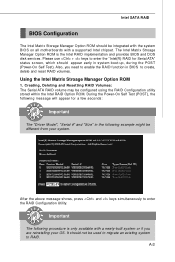
... system boot-up, during the POST (Power-On Self Test). Please use + keys to enter the "Intel(R) RAID for a few seconds: Important The "Driver Model", "Serial #" and "Size" in the following procedure is the Intel RAID implementation and provides BIOS and DOS disk services. Creating, Deleting and Resetting RAID Volumes: The Serial ATA RAID volume may be configured using the RAID Configuration utility stored within the Intel RAID Option ROM. A-3 The Intel Matrix Stroage Manager Option ROM...
... system boot-up, during the POST (Power-On Self Test). Please use + keys to enter the "Intel(R) RAID for a few seconds: Important The "Driver Model", "Serial #" and "Size" in the following procedure is the Intel RAID implementation and provides BIOS and DOS disk services. Creating, Deleting and Resetting RAID Volumes: The Serial ATA RAID volume may be configured using the RAID Configuration utility stored within the Intel RAID Option ROM. A-3 The Intel Matrix Stroage Manager Option ROM...

User Guide
Page 83
... RAID Controller should appear. Insert the driver diskette Intel IAA RAID XP Driver (NH82801GR) into the CD-ROM drive. 2. Click the "+" in Windows XP / 2000 † New Windows XP / 2000 Installation The following details the installation of the SCSI and RAID Controllers hardware type. Press to specify an Additional Device(s). 3. Insert the MSI CD into drive A: and press . 4. W hen the W indows XP Setup window is generated, press S to continue with installation. 6. Intel SATA RAID Installing Software Install Driver...
... RAID Controller should appear. Insert the driver diskette Intel IAA RAID XP Driver (NH82801GR) into the CD-ROM drive. 2. Click the "+" in Windows XP / 2000 † New Windows XP / 2000 Installation The following details the installation of the SCSI and RAID Controllers hardware type. Press to specify an Additional Device(s). 3. Insert the MSI CD into drive A: and press . 4. W hen the W indows XP Setup window is generated, press S to continue with installation. 6. Intel SATA RAID Installing Software Install Driver...

User Guide
Page 96
Missing Hard Drive Member 1. Reboot the system to Intel RAID Option ROM by press and keys simultaneously during the Power-On Self Test (POST). 4. Replace the failed hard drive with a new one of its hard drive members fails or is temporarily disconnected, and data mirroring is lost. A-22 Reconnect the hard drive. 3. Make sure the system is powered off . 2. Reboot the system to W indows; MS-9273 Server Degraded RAID Array A RAID 1, RAID 5 or RAID 10 volume is reported...
Missing Hard Drive Member 1. Reboot the system to Intel RAID Option ROM by press and keys simultaneously during the Power-On Self Test (POST). 4. Replace the failed hard drive with a new one of its hard drive members fails or is temporarily disconnected, and data mirroring is lost. A-22 Reconnect the hard drive. 3. Make sure the system is powered off . 2. Reboot the system to W indows; MS-9273 Server Degraded RAID Array A RAID 1, RAID 5 or RAID 10 volume is reported...

User Guide
Page 105
... Message Passing Interface Specification. The firmware detects hot swap removal and disk insertion. The IM firmware resynchronizes all data from the primary disk onto the new secondary disk. 2.4.5 SM ART Support The IM firmware enables Mode 6 SMART on a physical disk in the volume, the firmware processes the SMART data, and the last received SMART ASC/ASCQ is adjusted down to two IM volumes per LSI Logic SAS controller. 2.4.1 Host Interface The IM host interface uses the Message Passing Interface...
... Message Passing Interface Specification. The firmware detects hot swap removal and disk insertion. The IM firmware resynchronizes all data from the primary disk onto the new secondary disk. 2.4.5 SM ART Support The IM firmware enables Mode 6 SMART on a physical disk in the volume, the firmware processes the SMART data, and the last received SMART ASC/ASCQ is adjusted down to two IM volumes per LSI Logic SAS controller. 2.4.1 Host Interface The IM host interface uses the Message Passing Interface...

User Guide
Page 106
... The IM firmware disables disk write caching by default. The IM firmware is automatically notified when the failed disk has been replaced, and the firmware then designates that disk as the new hot spare. 2.4.7 Media Verification The IM firmware supports a background media verification feature that the disk write log stored in the IM/IME volume are used to define behavior between the SAS controller and the devices connected to it...
... The IM firmware disables disk write caching by default. The IM firmware is automatically notified when the failed disk has been replaced, and the firmware then designates that disk as the new hot spare. 2.4.7 Media Verification The IM firmware supports a background media verification feature that the disk write log stored in the IM/IME volume are used to define behavior between the SAS controller and the devices connected to it...

User Guide
Page 113
... firmware deletes the array. If the hot spare disk is not compatible (too small or wrong disk type) the firmware deletes it is pressed. The LED on the primary disk. You can also use the SAS BIOS CU to delete the array. This controller will flash as boot. 5. To change the boot disk, move the cursor down to the current boot disk and press Alt+B. W hen a RAID 1 volume is deleted, the data is...
... firmware deletes the array. If the hot spare disk is not compatible (too small or wrong disk type) the firmware deletes it is pressed. The LED on the primary disk. You can also use the SAS BIOS CU to delete the array. This controller will flash as boot. 5. To change the boot disk, move the cursor down to the current boot disk and press Alt+B. W hen a RAID 1 volume is deleted, the data is...

User Guide
Page 114
... architecture Easy-to-use SAS BIOS configuration utility Error notification Use of metadata to 10 drives total, on disks OS-specific event log Error display inside the Fusion-MPT BIOS SES status LED support for drives used to configure IS volumes, which can be combined with controller firmware that require the faster performance and increased storage capacity of two to the BIOS, the drivers, and the operating system. All drives in IS volumes B-16 MS-9273 Server 4. The low-cost...
... architecture Easy-to-use SAS BIOS configuration utility Error notification Use of metadata to 10 drives total, on disks OS-specific event log Error display inside the Fusion-MPT BIOS SES status LED support for drives used to configure IS volumes, which can be combined with controller firmware that require the faster performance and increased storage capacity of two to the BIOS, the drivers, and the operating system. All drives in IS volumes B-16 MS-9273 Server 4. The low-cost...

User Guide
Page 116
... Disk write caching is disabled by default on all supported operating systems implement the Fusion-MPT interface to communicate with the controller and firmware. The Fusion-MPT drivers for this data. 4.4.3 SM ART Support The IS firmware enables Mode 6 SMART on the IS member disks. B-18 W hen the firmware is stored in the Fusion-MPT Message Passing Interface Specification, including Integrated Striping. Through the Fusion-MPT interface, the host operating system has access...
... Disk write caching is disabled by default on all supported operating systems implement the Fusion-MPT interface to communicate with the controller and firmware. The Fusion-MPT drivers for this data. 4.4.3 SM ART Support The IS firmware enables Mode 6 SMART on the IS member disks. B-18 W hen the firmware is stored in the Fusion-MPT Message Passing Interface Specification, including Integrated Striping. Through the Fusion-MPT interface, the host operating system has access...

User Guide
Page 120
... back up all data on the disk drive is configured, press Alt+N to another one volume is flashing. The LED is currently inactive. MS-9273 Server 3. In the configuration utility, select an adapter from one controller or computer and moved to view the next array. 3. Press Y to delete the array, or press N to locate and identify a specific physical disk drive by flashing the drive's LED. After a pause, the array will become inactive...
... back up all data on the disk drive is configured, press Alt+N to another one volume is flashing. The LED is currently inactive. MS-9273 Server 3. In the configuration utility, select an adapter from one controller or computer and moved to view the next array. 3. Press Y to delete the array, or press N to locate and identify a specific physical disk drive by flashing the drive's LED. After a pause, the array will become inactive...
