
User Manual
Page 12
... 2 Installing a Processor 3 Installing DDR4 memory 4 Connecting the Front Panel Header 5 Installing the Motherboard 6 Connecting the Power Connectors 7 Installing SATA Drives 8 Installing a Graphics Card 9 Connecting Peripheral Devices 10 Power On...11 Specifications...15 JCORSAIR1 Connector Specification 20 Package contents 20 Block Diagram ...21 Rear I/O Panel...22 LAN Port LED Status Table 22 Audio Ports Configuration 22 Realtek Audio Console 23 Installing Antennas (TRX40 PRO WIFI 25 Overview of Components 26 CPU Socket...28 DIMM Slots...31 PCI_E1~5: PCIe Expansion Slots 33...
... 2 Installing a Processor 3 Installing DDR4 memory 4 Connecting the Front Panel Header 5 Installing the Motherboard 6 Connecting the Power Connectors 7 Installing SATA Drives 8 Installing a Graphics Card 9 Connecting Peripheral Devices 10 Power On...11 Specifications...15 JCORSAIR1 Connector Specification 20 Package contents 20 Block Diagram ...21 Rear I/O Panel...22 LAN Port LED Status Table 22 Audio Ports Configuration 22 Realtek Audio Console 23 Installing Antennas (TRX40 PRO WIFI 25 Overview of Components 26 CPU Socket...28 DIMM Slots...31 PCI_E1~5: PCIe Expansion Slots 33...

User Manual
Page 13
...: Power Button, Reset Button 44 JSLOW1: Slow Mode Booting Jumper 44 JBAT1: Clear CMOS (Reset BIOS) Jumper 45 JCI1: Chassis Intrusion Connector 46 JRGB1: RGB LED connector 47 JRAINBOW1~2: Addressable RGB LED connectors 48 JCORSAIR1: CORSAIR Connector 49 Onboard LEDs...50 EZ Debug LED...50 Debug Code LED...50 Hexadecimal Character Table 50 Boot Phases...50 Debug Code LED Table 51 ACPI States Codes 55 Installing OS, Drivers & Utilities 56 Installing Windows® 10 56 Installing Drivers 56 Installing Utilities 56 BIOS Setup...57 Entering BIOS Setup 57 Resetting BIOS...58 Updating...
...: Power Button, Reset Button 44 JSLOW1: Slow Mode Booting Jumper 44 JBAT1: Clear CMOS (Reset BIOS) Jumper 45 JCI1: Chassis Intrusion Connector 46 JRGB1: RGB LED connector 47 JRAINBOW1~2: Addressable RGB LED connectors 48 JCORSAIR1: CORSAIR Connector 49 Onboard LEDs...50 EZ Debug LED...50 Debug Code LED...50 Hexadecimal Character Table 50 Boot Phases...50 Debug Code LED Table 51 ACPI States Codes 55 Installing OS, Drivers & Utilities 56 Installing Windows® 10 56 Installing Drivers 56 Installing Utilities 56 BIOS Setup...57 Entering BIOS Setup 57 Resetting BIOS...58 Updating...

User Manual
Page 17
...;1x Chassis Intrusion connector ∙∙1x 4-pin 5050 RGB LED connector ∙∙2x 3-pin ARGB LED connectors ∙∙1x 3-pin CORSAIR LED connector ∙∙1x Slow mode booting jumper ∙∙1x Power button ∙∙1x Reset button ∙∙4x EZ Debug LED ∙∙1x 2-Digit Debug Code LED NUVOTON NCT6797 Controller Chip ∙∙CPU/System/Chipset temperature detection ∙∙CPU/System/Chipset fan speed detection ∙∙CPU/System/Chipset fan speed control ∙∙ATX...
...;1x Chassis Intrusion connector ∙∙1x 4-pin 5050 RGB LED connector ∙∙2x 3-pin ARGB LED connectors ∙∙1x 3-pin CORSAIR LED connector ∙∙1x Slow mode booting jumper ∙∙1x Power button ∙∙1x Reset button ∙∙4x EZ Debug LED ∙∙1x 2-Digit Debug Code LED NUVOTON NCT6797 Controller Chip ∙∙CPU/System/Chipset temperature detection ∙∙CPU/System/Chipset fan speed detection ∙∙CPU/System/Chipset fan speed control ∙∙ATX...

User Manual
Page 48
...;Always turn off the power supply and unplug the power cord from the power outlet before installing or removing the RGB LED strip. ∙∙Please use MSI's software to connect the WS2812B Individually Addressable RGB LED strips 5V. 1 1 +5V 2 3 No Pin 4 Data Ground Addressable RGB LED Strip Connection 1 +5V D JRAINBOW connector Rainbow RGB LED extension cable Addressable RGB LED Fan Connection JRAINBOW connector 1 WS2812B Individually Addressable RGB LED strips 5V 1 System Fan connector Addressable RGB LED Fan...
...;Always turn off the power supply and unplug the power cord from the power outlet before installing or removing the RGB LED strip. ∙∙Please use MSI's software to connect the WS2812B Individually Addressable RGB LED strips 5V. 1 1 +5V 2 3 No Pin 4 Data Ground Addressable RGB LED Strip Connection 1 +5V D JRAINBOW connector Rainbow RGB LED extension cable Addressable RGB LED Fan Connection JRAINBOW connector 1 WS2812B Individually Addressable RGB LED strips 5V 1 System Fan connector Addressable RGB LED Fan...

User Manual
Page 51
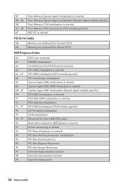
Debug Code LED Table SEC Progress Codes 01 Power on. Configuring memory Memory initialization (other) Memory Installed CPU post-memory initialization is started CPU post-memory initialization. Memory presence detection Memory initialization. Cache initialization CPU post-memory initialization. Programming memory timing information Memory initialization. Application Processor(s) (AP) initialization CPU post-memory initialization. System Management Mode (SMM) initialization Onboard LEDs 51 Reset type detection (soft/hard) 02 AP initialization before microcode loading 03 System ...
Debug Code LED Table SEC Progress Codes 01 Power on. Configuring memory Memory initialization (other) Memory Installed CPU post-memory initialization is started CPU post-memory initialization. Memory presence detection Memory initialization. Cache initialization CPU post-memory initialization. Programming memory timing information Memory initialization. Application Processor(s) (AP) initialization CPU post-memory initialization. System Management Mode (SMM) initialization Onboard LEDs 51 Reset type detection (soft/hard) 02 AP initialization before microcode loading 03 System ...
User Manual
Page 52
... Agent module specific) PCH DXE initialization is started PCH DXE SMM initialization is started PCH devices initialization PCH DXE Initialization (PCH module specific) ACPI module initialization CSM initialization Reserved for future AMI DXE codes Boot Device Selection (BDS) phase is started Driver connecting is started PCI Bus initialization is started PCI Bus Hot Plug Controller Initialization PCI Bus Enumeration 32 PCI Bus Request Resources PCI Bus Assign Resources Console Output devices connect Console input devices connect Super IO Initialization 52 Onboard LEDs
... Agent module specific) PCH DXE initialization is started PCH DXE SMM initialization is started PCH devices initialization PCH DXE Initialization (PCH module specific) ACPI module initialization CSM initialization Reserved for future AMI DXE codes Boot Device Selection (BDS) phase is started Driver connecting is started PCI Bus initialization is started PCI Bus Hot Plug Controller Initialization PCI Bus Enumeration 32 PCI Bus Request Resources PCI Bus Assign Resources Console Output devices connect Console input devices connect Super IO Initialization 52 Onboard LEDs
User Manual
Page 53
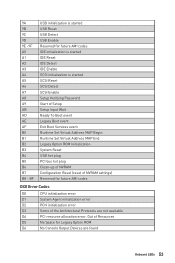
...USB initialization is started USB Reset USB Detect USB Enable Reserved for future AMI codes IDE initialization is started IDE Reset IDE Detect IDE Enable SCSI initialization is started SCSI Reset SCSI Detect SCSI Enable Setup Verifying Password Start of Setup Setup Input Wait Ready To Boot event Legacy Boot event Exit Boot Services event Runtime Set Virtual Address MAP Begin Runtime Set Virtual Address MAP End Legacy Option ROM Initialization System Reset USB hot plug PCI bus hot plug Clean-up of NVRAM Configuration Reset (reset of NVRAM settings) Reserved for future AMI codes DXE Error Codes...
...USB initialization is started USB Reset USB Detect USB Enable Reserved for future AMI codes IDE initialization is started IDE Reset IDE Detect IDE Enable SCSI initialization is started SCSI Reset SCSI Detect SCSI Enable Setup Verifying Password Start of Setup Setup Input Wait Ready To Boot event Legacy Boot event Exit Boot Services event Runtime Set Virtual Address MAP Begin Runtime Set Virtual Address MAP End Legacy Option ROM Initialization System Reset USB hot plug PCI bus hot plug Clean-up of NVRAM Configuration Reset (reset of NVRAM settings) Reserved for future AMI codes DXE Error Codes...

User Manual
Page 56
... POST (Power-On Self Test) to choose what happens with this disc pop-up your computer in Windows® 10. 2. message. 7. Click the Select to get into your computer. 56 Installing OS, Drivers & Utilities Click OK button to finish. 8. Installing OS, Drivers & Utilities Please download and update the latest utilities and drivers at www.msi.com Installing Windows® 10 1. Power on the screen to boot from the Boot Menu. 6. Press any key...
... POST (Power-On Self Test) to choose what happens with this disc pop-up your computer in Windows® 10. 2. message. 7. Click the Select to get into your computer. 56 Installing OS, Drivers & Utilities Click OK button to finish. 8. Installing OS, Drivers & Utilities Please download and update the latest utilities and drivers at www.msi.com Installing Windows® 10 1. Power on the screen to boot from the Boot Menu. 6. Press any key...
User Manual
Page 58
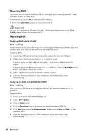
... to perform the BIOS update process. 4. Select BIOS Update. 3. Updating BIOS: 1. Click on Scan button. 4. And then click Next and Start to download and install the latest BIOS file. 5. Please refer to the Clear CMOS jumper section for resetting BIOS. Insert the USB flash drive that matches your motherboard model from MSI website. Click Next and choose In Windows mode. Updating BIOS Updating BIOS with DRAGON CENTER Before updating: Make sure the LAN driver is already installed and the Internet connection is 100% completed...
... to perform the BIOS update process. 4. Select BIOS Update. 3. Updating BIOS: 1. Click on Scan button. 4. And then click Next and Start to download and install the latest BIOS file. 5. Please refer to the Clear CMOS jumper section for resetting BIOS. Insert the USB flash drive that matches your motherboard model from MSI website. Click Next and choose In Windows mode. Updating BIOS Updating BIOS with DRAGON CENTER Before updating: Make sure the LAN driver is already installed and the Internet connection is 100% completed...

User Manual
Page 59
... your motherboard model from the MSI® website. 2. Press the Flash BIOS Button to install CPU and memory.) 4. Updating BIOS with Flash BIOS Button 1. Please download the latest BIOS file that contains the MSI.ROM file into the Flash BIOS Port on the drive icon and go to Properties. BIOS Setup 59 The LED will be turned off when the process is completed. ⚠⚠Important Only the FAT32 format USB flash drive supports updating BIOS by Flash BIOS Button. To check your USB flash drive (FAT32 format). 3. Connect the power supply to...
... your motherboard model from the MSI® website. 2. Press the Flash BIOS Button to install CPU and memory.) 4. Updating BIOS with Flash BIOS Button 1. Please download the latest BIOS file that contains the MSI.ROM file into the Flash BIOS Port on the drive icon and go to Properties. BIOS Setup 59 The LED will be turned off when the process is completed. ⚠⚠Important Only the FAT32 format USB flash drive supports updating BIOS by Flash BIOS Button. To check your USB flash drive (FAT32 format). 3. Connect the power supply to...

User Manual
Page 60
... and save it to change the boot priority. Move the mouse over a blank space and right click the mouse to enable/ disable the A-XMP. shows the CPU/ DDR speed, CPU/ MB temperature, MB/ CPU type, memory size, CPU/ DDR voltage, BIOS version and build date. ∙∙ Boot device priority bar - A-XMP switch Setup Mode switch Screenshot Search Language System information OC GENIE 4 switch Information display Boot device priority bar M-Flash Favorites Hardware Monitor Function buttons ∙∙ OC...
... and save it to change the boot priority. Move the mouse over a blank space and right click the mouse to enable/ disable the A-XMP. shows the CPU/ DDR speed, CPU/ MB temperature, MB/ CPU type, memory size, CPU/ DDR voltage, BIOS version and build date. ∙∙ Boot device priority bar - A-XMP switch Setup Mode switch Screenshot Search Language System information OC GENIE 4 switch Information display Boot device priority bar M-Flash Favorites Hardware Monitor Function buttons ∙∙ OC...

User Manual
Page 61
... fan speed by clicking on search page. 2. Move the mouse over a BIOS item on left side to enter Favorites menu. ∙∙ Information display - click on this button to display the Hardware Monitor menu that provides the way to select a BIOS menu (e.g. allows you to a favorite page (Favorite 1~5) 1. SETTINGS, OC...,etc) as the BIOS home page. ▪▪Favorite1~5 - enable or disable the LAN Option ROM, CSM/UEFI, HD Audio Controller, AHCI, RAID, Indication LED Control...
... fan speed by clicking on search page. 2. Move the mouse over a BIOS item on left side to enter Favorites menu. ∙∙ Information display - click on this button to display the Hardware Monitor menu that provides the way to select a BIOS menu (e.g. allows you to a favorite page (Favorite 1~5) 1. SETTINGS, OC...,etc) as the BIOS home page. ▪▪Favorite1~5 - enable or disable the LAN Option ROM, CSM/UEFI, HD Audio Controller, AHCI, RAID, Indication LED Control...
User Manual
Page 64
..., such as LAN, HDD, USB and audio. Press Enter to utilize more than 4x GPUs. [Disabled] Disables this function. ▶▶PCIe SlotX Lanes Configuration PCIe lanes configuration for MSI M.2 XPANDER series cards/ Other M.2 PCIe storage card. ▶▶ACPI Settings Sets ACPI parameters of the onboard Power LED. [Dual Color] The power LED turns to another color to indicate the S3 state. [Blinking] The power LED blinks to be configured automatically by BIOS. [Gen1] Enables PCIe Gen1 support only. [Gen2] Enables PCIe Gen2 support only. [Gen3] Enables PCIe Gen3 support only...
..., such as LAN, HDD, USB and audio. Press Enter to utilize more than 4x GPUs. [Disabled] Disables this function. ▶▶PCIe SlotX Lanes Configuration PCIe lanes configuration for MSI M.2 XPANDER series cards/ Other M.2 PCIe storage card. ▶▶ACPI Settings Sets ACPI parameters of the onboard Power LED. [Dual Color] The power LED turns to another color to indicate the S3 state. [Blinking] The power LED blinks to be configured automatically by BIOS. [Gen1] Enables PCIe Gen1 support only. [Gen2] Enables PCIe Gen2 support only. [Gen3] Enables PCIe Gen3 support only...

User Manual
Page 65
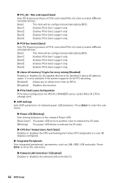
...9654;Legacy USB Support [Enabled] Sets Legacy USB function support. [Auto] The system will be unavailable under legacy mode. BIOS Setup 65 Press Enter to enable or disable the SATA hot plug support. [Enabled] Enables hot plug support for the SATA ports. [Disabled] Disables hot plug support for optimizing IPv4 / IPv6 function. This item is available when Onboard LAN Controller/ 2 is Enabled. [Enabled] Enables the Ipv4 PXE boot support. [Disabled] Disables the Ipv4 PXE boot support. ▶▶Ipv6 PXE Support [Enabled] When Enabled, the system UEFI network stack will support Ipv4...
...9654;Legacy USB Support [Enabled] Sets Legacy USB function support. [Auto] The system will be unavailable under legacy mode. BIOS Setup 65 Press Enter to enable or disable the SATA hot plug support. [Enabled] Enables hot plug support for the SATA ports. [Disabled] Disables hot plug support for optimizing IPv4 / IPv6 function. This item is available when Onboard LAN Controller/ 2 is Enabled. [Enabled] Enables the Ipv4 PXE boot support. [Disabled] Disables the Ipv4 PXE boot support. ▶▶Ipv6 PXE Support [Enabled] When Enabled, the system UEFI network stack will support Ipv4...

User Manual
Page 66
... BIOS UEFI/CSM Mode sets to UEFI. ▶▶Secure Boot Sets the Windows secure boot to enter the sub-menu. This sub-menu will not support S4 & S5 wake up by USB and PCIe devices. [Disabled] Disables this function. ▶▶Restore after AC Power Loss [Power Off] Sets the system behaviors while encountering the AC power loss. [Power Off] Leaves the system in power off ) before AC power loss. ▶▶System Power Fault Protection [Disabled] Enables...
... BIOS UEFI/CSM Mode sets to UEFI. ▶▶Secure Boot Sets the Windows secure boot to enter the sub-menu. This sub-menu will not support S4 & S5 wake up by USB and PCIe devices. [Disabled] Disables this function. ▶▶Restore after AC Power Loss [Power Off] Sets the system behaviors while encountering the AC power loss. [Power Off] Leaves the system in power off ) before AC power loss. ▶▶System Power Fault Protection [Disabled] Enables...

User Manual
Page 67
... By PCI-E Device [Disabled] Enables or disables the wake up function of installed PCI-E expansion cards, integrated LAN controllers or USB devices which are supported by third party integrated chips. [Enabled] Enables the system to be erased after enabling Secure Erase+. ▶▶Intel ( R ) I211 Gigabit Network Connection Shows driver information and configuration of the Ethernet controller parameter. ▶▶Intel ( R ) I211 Gigabit Network Connection Shows driver information and configuration of system boot devices. ▶▶Full Screen Logo Display [Enabled] Enables...
... By PCI-E Device [Disabled] Enables or disables the wake up function of installed PCI-E expansion cards, integrated LAN controllers or USB devices which are supported by third party integrated chips. [Enabled] Enables the system to be erased after enabling Secure Erase+. ▶▶Intel ( R ) I211 Gigabit Network Connection Shows driver information and configuration of the Ethernet controller parameter. ▶▶Intel ( R ) I211 Gigabit Network Connection Shows driver information and configuration of system boot devices. ▶▶Full Screen Logo Display [Enabled] Enables...

User Manual
Page 69
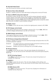
... being disabled. The password typed now will replace any change. ▶▶Save Changes and Reboot Save all changes and reboot the system. ▶▶Save Changes Save current changes. ▶▶Discard Changes Discard all default values. ▶▶Boot Override The installed boot-able devices will appear on the screen. A message will confirm the password is ready for accessing the system. ▶▶Chassis Intrusion Configuration Press Enter to...
... being disabled. The password typed now will replace any change. ▶▶Save Changes and Reboot Save all changes and reboot the system. ▶▶Save Changes Save current changes. ▶▶Discard Changes Discard all default values. ▶▶Boot Override The installed boot-able devices will appear on the screen. A message will confirm the password is ready for accessing the system. ▶▶Chassis Intrusion Configuration Press Enter to...
User Manual
Page 71
... enter the BIOS to load the default settings.) ▶▶DigitALL Power Press Enter to enter the sub-menu. Controls the digital powers related to CPU PWM. ▶▶CPU Voltages control [Auto] These options allows you have to load the default settings for each/ all the settings and timings of installed CPU. This sub-menu displays all memory channel. The sub-menu displays the information of installed CPU. If set to Auto, BIOS will issue a warning message during boot when the CPU or memory has been replaced. [Enabled] [Disabled...
... enter the BIOS to load the default settings.) ▶▶DigitALL Power Press Enter to enter the sub-menu. Controls the digital powers related to CPU PWM. ▶▶CPU Voltages control [Auto] These options allows you have to load the default settings for each/ all the settings and timings of installed CPU. This sub-menu displays all memory channel. The sub-menu displays the information of installed CPU. If set to Auto, BIOS will issue a warning message during boot when the CPU or memory has been replaced. [Enabled] [Disabled...
User Manual
Page 80
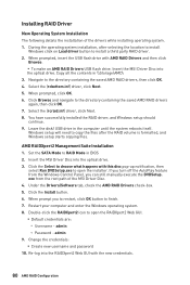
... with AMD RAID Drivers and then click Browse. ▪▪To make an AMD RAID Drivers USB flash drive. When prompted, insert the USB flash drive with the new credentials. 80 AMD RAID Configuration Select the (rcbottom.inf) driver, click Next. 5. When prompted, click OK. 6. Leave the disk/ USB drive in \\Storage\AMD\ 3. Set the SATA Mode to the directory containing the saved AMD RAID drivers again, then click OK. 7. exe from the Windows Control Panel, you can still manually execute...
... with AMD RAID Drivers and then click Browse. ▪▪To make an AMD RAID Drivers USB flash drive. When prompted, insert the USB flash drive with the new credentials. 80 AMD RAID Configuration Select the (rcbottom.inf) driver, click Next. 5. When prompted, click OK. 6. Leave the disk/ USB drive in \\Storage\AMD\ 3. Set the SATA Mode to the directory containing the saved AMD RAID drivers again, then click OK. 7. exe from the Windows Control Panel, you can still manually execute...

User Manual
Page 81
... USB port on the motherboard rear IO panel. ∙∙Remove secondary speakers/ headphones, HDMI cables, USB audio devices. ∙∙Test with another known working speaker or headphone. Lost BIOS password ∙∙Clear the CMOS, but no network ∙∙Make sure the network chipset driver has been installed. ∙∙Verify if the network cable is properly connected and make sure the button is turned on. ∙∙Check if the power switch cable is connected to JFP1 pin header...
... USB port on the motherboard rear IO panel. ∙∙Remove secondary speakers/ headphones, HDMI cables, USB audio devices. ∙∙Test with another known working speaker or headphone. Lost BIOS password ∙∙Clear the CMOS, but no network ∙∙Make sure the network chipset driver has been installed. ∙∙Verify if the network cable is properly connected and make sure the button is turned on. ∙∙Check if the power switch cable is connected to JFP1 pin header...

