

User Guide
Page 2
.... The internal view of the installation. Pliers, can be used to pick up tiny screws or set up the jumpers. Getting Started How to Use this guide from being incised and suffering the static charge. Important All information is subject to change without prior notice. The system photos are highly recommended to read this Service Manual This Service Manual is...
.... The internal view of the installation. Pliers, can be used to pick up tiny screws or set up the jumpers. Getting Started How to Use this guide from being incised and suffering the static charge. Important All information is subject to change without prior notice. The system photos are highly recommended to read this Service Manual This Service Manual is...
User Guide
Page 3
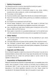
... perform any maintenance with wet hands. Prevent foreign substances, such as CPU, Memory, HDD, mini PCI-E card, etc. Place system components on a grounded antistatic pad or on the bed that the acquisition of replaceable parts (or compatible ones) of their respective owners. The information contained herein relevant to upgrade or replace any upgrade or replace service. Acquisition of Replaceable Parts Please be...
... perform any maintenance with wet hands. Prevent foreign substances, such as CPU, Memory, HDD, mini PCI-E card, etc. Place system components on a grounded antistatic pad or on the bed that the acquisition of replaceable parts (or compatible ones) of their respective owners. The information contained herein relevant to upgrade or replace any upgrade or replace service. Acquisition of Replaceable Parts Please be...

User Guide
Page 4
Place the system horizontally on the back side and keep them for later use . Step 3. Remove the cover carefully and set it aside for later use . 3 Step 1. Unlock the two screws on a flat and steady surface. Step 2. System Assembly Cover & HDD Holder Important Before you remove or install any components, make sure the system is not turned on or connected to the AC power.
Place the system horizontally on the back side and keep them for later use . Step 3. Remove the cover carefully and set it aside for later use . 3 Step 1. Unlock the two screws on a flat and steady surface. Step 2. System Assembly Cover & HDD Holder Important Before you remove or install any components, make sure the system is not turned on or connected to the AC power.
User Guide
Page 5
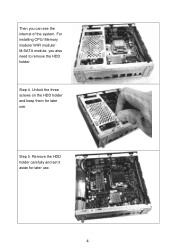
For installing CPU/ Memory module/ WIFI module/ M-SATA module, you can see the internal of the system. Step 5. Unlock the three screws on the HDD holder and keep them for later use . Remove the HDD holder carefully and set it aside for later use . 4 Step 4. Then you also need to remove the HDD holder.
For installing CPU/ Memory module/ WIFI module/ M-SATA module, you can see the internal of the system. Step 5. Unlock the three screws on the HDD holder and keep them for later use . Remove the HDD holder carefully and set it aside for later use . 4 Step 4. Then you also need to remove the HDD holder.
User Guide
Page 6
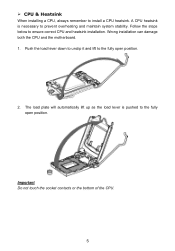
Follow the steps below to install a CPU heatsink. Important Do not touch the socket contacts or the bottom of the CPU. 5 CPU & Heatsink When installing a CPU, always remember to ensure correct CPU and heatsink installation. Push the load lever down to unclip it and lift to the fully open position. 2. The load plate will automatically lift up as the load lever is necessary to prevent overheating and maintain system stability. A CPU heatsink is pushed to the fully open position. Wrong installation can damage both the CPU and the motherboard. 1.
Follow the steps below to install a CPU heatsink. Important Do not touch the socket contacts or the bottom of the CPU. 5 CPU & Heatsink When installing a CPU, always remember to ensure correct CPU and heatsink installation. Push the load lever down to unclip it and lift to the fully open position. 2. The load plate will automatically lift up as the load lever is necessary to prevent overheating and maintain system stability. A CPU heatsink is pushed to the fully open position. Wrong installation can damage both the CPU and the motherboard. 1.
User Guide
Page 7
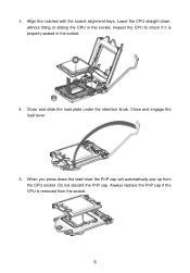
Close and slide the load plate under the retention knob. Close and engage the load lever. 5. Lower the CPU straight down the load lever the PnP cap will automatically pop up from the socket. 6 Align the notches with the socket alignment keys. Always replace the PnP cap if the CPU is properly seated in the socket. Do not discard the PnP cap. When you press down , without tilting or sliding the CPU in the socket. 4. Inspect the CPU to check if it is removed from the CPU socket. 3.
Close and slide the load plate under the retention knob. Close and engage the load lever. 5. Lower the CPU straight down the load lever the PnP cap will automatically pop up from the socket. 6 Align the notches with the socket alignment keys. Always replace the PnP cap if the CPU is properly seated in the socket. Do not discard the PnP cap. When you press down , without tilting or sliding the CPU in the socket. 4. Inspect the CPU to check if it is removed from the CPU socket. 3.

User Guide
Page 8
... tape) on the motherboard. 8. Locate the CPU fan connector on the top of the CPU. As each fastener locks into the holes on the motherboard. 9. Push down to ensure that the fastener-ends have been properly locked in heat dissipation and prevent CPU overheating. 7. Place the heatsink on the motherboard with the fan cable facing towards the fan connector and the fasteners matching...
... tape) on the motherboard. 8. Locate the CPU fan connector on the top of the CPU. As each fastener locks into the holes on the motherboard. 9. Push down to ensure that the fastener-ends have been properly locked in heat dissipation and prevent CPU overheating. 7. Place the heatsink on the motherboard with the fan cable facing towards the fan connector and the fasteners matching...

User Guide
Page 9
Important Confirm that the CPU heatsink has formed a tight seal with the CPU before booting your system. Whenever the CPU is not installed, always protect the CPU socket pins by covering the socket with the plastic cap. If you purchased a separate CPU and heatsink/ cooler, Please refer to the CPU fan connector on the motherboard. 11. Finally, attach the CPU fan cable to the documentation in the heatsink/ cooler package for more details about installation. 8
Important Confirm that the CPU heatsink has formed a tight seal with the CPU before booting your system. Whenever the CPU is not installed, always protect the CPU socket pins by covering the socket with the plastic cap. If you purchased a separate CPU and heatsink/ cooler, Please refer to the CPU fan connector on the motherboard. 11. Finally, attach the CPU fan cable to the documentation in the heatsink/ cooler package for more details about installation. 8
User Guide
Page 10
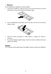
.... 3. Locate the SO-DIMM slot. Follow the above procedures to install another or replace the memory if necessary. 4. To avoid damaging the golden finger, remove the memory carefully at a 45-degree angle. 2. Important You can barely see the golden finger if the DIMM is intended for memory modules. 1. Align the notch on the memory with the key on the slot and...
.... 3. Locate the SO-DIMM slot. Follow the above procedures to install another or replace the memory if necessary. 4. To avoid damaging the golden finger, remove the memory carefully at a 45-degree angle. 2. Important You can barely see the golden finger if the DIMM is intended for memory modules. 1. Align the notch on the memory with the key on the slot and...

User Guide
Page 11
... wire to the antenna connector on the back panel. Step 2. Step 3. Then push it in the right direction. Adjust the antenna to the proper position. Step 1. Press the wireless LAN card down and then lock the screw. Note: For the optional Bluetooth module, connect also the Bluetooth antenna wire and the Bluetooth antenna. 10 Wireless LAN Card and Antenna Important The wireless LAN card...
... wire to the antenna connector on the back panel. Step 2. Step 3. Then push it in the right direction. Adjust the antenna to the proper position. Step 1. Press the wireless LAN card down and then lock the screw. Note: For the optional Bluetooth module, connect also the Bluetooth antenna wire and the Bluetooth antenna. 10 Wireless LAN Card and Antenna Important The wireless LAN card...
User Guide
Page 12
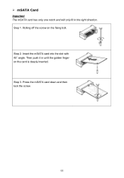
Press the mSATA card down and then lock the screw. 11 Step 2. Step 1. Then push it in the right direction. Insert the mSATA card into the slot with 45° angle. mSATA Card Important The mSATA card has only one notch and will only fit in until the golden finger on the fixing bolt. Step 3. Rolling off the screw on the card is deeply inserted.
Press the mSATA card down and then lock the screw. 11 Step 2. Step 1. Then push it in the right direction. Insert the mSATA card into the slot with 45° angle. mSATA Card Important The mSATA card has only one notch and will only fit in until the golden finger on the fixing bolt. Step 3. Rolling off the screw on the card is deeply inserted.
User Guide
Page 13
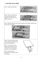
Connect the SATA power cord and SATA signal cable to install another HDD if necessary. 12 Note 2: Follow the above procedures to the board and the HDD drive. Step 3. Step 4. Take out and press the four plastic spacers from the bigger hole on the holder and then fix the screws with a screwdriver. Slide the HDD drive into the correct position on the holder to the SATA power connector on the motherboard. Locate the HDD holder. Hard Disk Drive (HDD) Step 1. Step 2. Note 1: If you received a 1to2 SATA power cable, connect the middle end to the smaller fixing hole.
Connect the SATA power cord and SATA signal cable to install another HDD if necessary. 12 Note 2: Follow the above procedures to the board and the HDD drive. Step 3. Step 4. Take out and press the four plastic spacers from the bigger hole on the holder and then fix the screws with a screwdriver. Slide the HDD drive into the correct position on the holder to the SATA power connector on the motherboard. Locate the HDD holder. Hard Disk Drive (HDD) Step 1. Step 2. Note 1: If you received a 1to2 SATA power cable, connect the middle end to the smaller fixing hole.
User Guide
Page 14
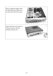
Place the cover back and fix the four screws. Arrange the cables. Step 6. Place the HDD holder with HDD drive to the case and fix the three screws. Then the hardware setting is done. 13 Step 5.
Place the cover back and fix the four screws. Arrange the cables. Step 6. Place the HDD holder with HDD drive to the case and fix the three screws. Then the hardware setting is done. 13 Step 5.


