User Manual
Page 3
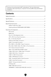
... Panel Connectors 9 LAN Port LED Status Table 10 Installing antennas (PRO B660M-A WIFI DDR4 11 Overview of Components 12 CPU Socket...13 DIMM Slots...14 PCI_E1~3: PCIe Expansion Slots 15 JFP1, JFP2: Front Panel Connectors 15 M2_1~2: M.2 Slots (Key M 16 SATA5~8: SATA 6Gb/s Connectors 18 JAUD1: Front Audio Connector 18 CPU_PWR1~2, ATX_PWR1: Power Connectors 19 CPU_FAN1, PUMP_FAN1, SYS_FAN1~2: Fan Connectors 20 JCI1: Chassis Intrusion Connector 21 JBAT1: Clear CMOS (Reset BIOS) Jumper 21 JUSB4: USB 3.2 Gen 1 5Gbps Type-C Connector 22 JUSB3: USB 3.2 Gen 1 Connector 22 JUSB1~2: USB...
... Panel Connectors 9 LAN Port LED Status Table 10 Installing antennas (PRO B660M-A WIFI DDR4 11 Overview of Components 12 CPU Socket...13 DIMM Slots...14 PCI_E1~3: PCIe Expansion Slots 15 JFP1, JFP2: Front Panel Connectors 15 M2_1~2: M.2 Slots (Key M 16 SATA5~8: SATA 6Gb/s Connectors 18 JAUD1: Front Audio Connector 18 CPU_PWR1~2, ATX_PWR1: Power Connectors 19 CPU_FAN1, PUMP_FAN1, SYS_FAN1~2: Fan Connectors 20 JCI1: Chassis Intrusion Connector 21 JBAT1: Clear CMOS (Reset BIOS) Jumper 21 JUSB4: USB 3.2 Gen 1 5Gbps Type-C Connector 22 JUSB3: USB 3.2 Gen 1 Connector 22 JUSB1~2: USB...

User Manual
Page 5
... any of breakage. ∙ Do not leave this motherboard away from the power outlet before installing or removing any installation step, please consult a certified computer technician. ∙ Always turn off the power supply and unplug the power cord from humidity. ∙ Make sure that your electrical outlet provides the same voltage as is recommended to wear an electrostatic discharge (ESD...
... any of breakage. ∙ Do not leave this motherboard away from the power outlet before installing or removing any installation step, please consult a certified computer technician. ∙ Always turn off the power supply and unplug the power cord from humidity. ∙ Make sure that your electrical outlet provides the same voltage as is recommended to wear an electrostatic discharge (ESD...

User Manual
Page 6
.... Specifications CPU Chipset Memory Expansion Slots Multi-GPU Onboard Graphics SATA Ports ∙ Supports 12th Gen Intel® Core™ Processors ∙ Processor socket LGA1700 * Please go to www.msi.com to www.msi.com for more information on compatible memory. ∙ 2x PCIe x16 slots • PCI_E1 (From CPU) • Support PCIe 4.0 x16 • PCI_E3 (From B660 chipset) • Support PCIe 3.0 x4 ∙ 1x PCIe 3.0 x1 slot (Fom B660 chipset) ∙ Supports AMD CrossFire™ Technology ∙ 2x HDMI 2.1 with HDR ports, supporting a maximum...
.... Specifications CPU Chipset Memory Expansion Slots Multi-GPU Onboard Graphics SATA Ports ∙ Supports 12th Gen Intel® Core™ Processors ∙ Processor socket LGA1700 * Please go to www.msi.com to www.msi.com for more information on compatible memory. ∙ 2x PCIe x16 slots • PCI_E1 (From CPU) • Support PCIe 4.0 x16 • PCI_E3 (From B660 chipset) • Support PCIe 3.0 x4 ∙ 1x PCIe 3.0 x1 slot (Fom B660 chipset) ∙ Supports AMD CrossFire™ Technology ∙ 2x HDMI 2.1 with HDR ports, supporting a maximum...
User Manual
Page 7
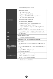
... CPU) • Supports up to PCIe 4.0 x4 • Supports 2242/ 2260/ 2280 storage devices • M2_2 slot (From B660 chipset) • Supports up to PCIe 4.0 x4 • Supports up to SATA 6Gb/s • Supports 2242/ 2260/ 2280 storage devices • Supports Intel® Optane™ Memory • Support Intel® Smart Response Technology for SATA storage devices Audio Realtek® ALC897 Codec ∙ 7.1-Channel High Definition Audio LAN 1x Realtek® RTL8125BG 2.5Gbps LAN controller Wi-Fi & Bluetooth® (PRO B660M-A WIFI DDR4...
... CPU) • Supports up to PCIe 4.0 x4 • Supports 2242/ 2260/ 2280 storage devices • M2_2 slot (From B660 chipset) • Supports up to PCIe 4.0 x4 • Supports up to SATA 6Gb/s • Supports 2242/ 2260/ 2280 storage devices • Supports Intel® Optane™ Memory • Support Intel® Smart Response Technology for SATA storage devices Audio Realtek® ALC897 Codec ∙ 7.1-Channel High Definition Audio LAN 1x Realtek® RTL8125BG 2.5Gbps LAN controller Wi-Fi & Bluetooth® (PRO B660M-A WIFI DDR4...
User Manual
Page 8
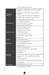
... Clear CMOS jumper LED Features ∙ 1x 4-pin RGB LED connector ∙ 2x 3-pin RAINBOW LED connectors ∙ 4x EZ Debug LED Back Panel Connectors ∙ 1x PS/2 mouse/ keyboard port ∙ 2x USB 2.0 Type-A ports (From B660 chipset) ∙ 2x DisplayPort ports ∙ 2x HDMI ports ∙ 2x USB 3.2 Gen 1 5Gbps Type-A ports (From B660 chipset) ∙ 2x USB 3.2 Gen 2 10Gbps Type-A ports (From B660 chipset) ∙ 1x 2.5G LAN (RJ45) port ∙ 2x Wi-Fi Antenna connectors (PRO B660M-A WIFI DDR4) ∙ 3x audio jacks I/O Controller...
... Clear CMOS jumper LED Features ∙ 1x 4-pin RGB LED connector ∙ 2x 3-pin RAINBOW LED connectors ∙ 4x EZ Debug LED Back Panel Connectors ∙ 1x PS/2 mouse/ keyboard port ∙ 2x USB 2.0 Type-A ports (From B660 chipset) ∙ 2x DisplayPort ports ∙ 2x HDMI ports ∙ 2x USB 3.2 Gen 1 5Gbps Type-A ports (From B660 chipset) ∙ 2x USB 3.2 Gen 2 10Gbps Type-A ports (From B660 chipset) ∙ 1x 2.5G LAN (RJ45) port ∙ 2x Wi-Fi Antenna connectors (PRO B660M-A WIFI DDR4) ∙ 3x audio jacks I/O Controller...

User Manual
Page 9
Hardware Monitor Form Factor BIOS Features Software Continued from previous column ∙ CPU/ System/ Chipset temperature detection ∙ CPU/ System/ Pump fan speed detection ∙ CPU/ System/ Pump fan speed control ∙ Micro-ATX Form Factor ∙ 9.6 in . (24.4 cm x 24.4 cm) ∙ 1x 256 Mb flash ∙ UEFI AMI BIOS ∙ ACPI 6.4, SMBIOS 3.4 ∙ Multi-language ∙ Drivers ∙ MSI Center ∙ Intel Extreme Tuning Utility ∙ CPU-Z MSI GAMING ∙ Google Chrome...
Hardware Monitor Form Factor BIOS Features Software Continued from previous column ∙ CPU/ System/ Chipset temperature detection ∙ CPU/ System/ Pump fan speed detection ∙ CPU/ System/ Pump fan speed control ∙ Micro-ATX Form Factor ∙ 9.6 in . (24.4 cm x 24.4 cm) ∙ 1x 256 Mb flash ∙ UEFI AMI BIOS ∙ ACPI 6.4, SMBIOS 3.4 ∙ Multi-language ∙ Drivers ∙ MSI Center ∙ Intel Extreme Tuning Utility ∙ CPU-Z MSI GAMING ∙ Google Chrome...

User Manual
Page 10
...; MSI Companion Audio • Audio Boost Network • 2.5G LAN • LAN Manager Cooling • Extended Heatsink Design • M.2 Shield Frozr • 7W/mK MOSFET thermal pad • Choke thermal pad • Pump Fan • Smart Fan Control LED • Mystic Light Extension (RAINBOW/ RGB) • Mystic Light SYNC • Ambient Devices Support Performance • Lightning Gen 4 (M.2/PCIE) • Memory Boost • Core Boost • Game Boost • USB 3.2 Gen...
...; MSI Companion Audio • Audio Boost Network • 2.5G LAN • LAN Manager Cooling • Extended Heatsink Design • M.2 Shield Frozr • 7W/mK MOSFET thermal pad • Choke thermal pad • Pump Fan • Smart Fan Control LED • Mystic Light Extension (RAINBOW/ RGB) • Mystic Light SYNC • Ambient Devices Support Performance • Lightning Gen 4 (M.2/PCIE) • Memory Boost • Core Boost • Game Boost • USB 3.2 Gen...

User Manual
Page 15
Always make sure the cooling fans work properly to protect the CPU from the power outlet before booting your system. ∙ Overheating can seriously damage the CPU and motherboard. A CPU heatsink is not installed, always protect the CPU socket pins by covering the socket with the plastic cap. ∙ If you purchased a separate CPU and heatsink/ cooler, Please refer to install a CPU heatsink. CPU Socket Please install the CPU into the CPU socket as shown below...
Always make sure the cooling fans work properly to protect the CPU from the power outlet before booting your system. ∙ Overheating can seriously damage the CPU and motherboard. A CPU heatsink is not installed, always protect the CPU socket pins by covering the socket with the plastic cap. ∙ If you purchased a separate CPU and heatsink/ cooler, Please refer to install a CPU heatsink. CPU Socket Please install the CPU into the CPU socket as shown below...

User Manual
Page 16
... of installed memory module depend on installed CPU and devices when overclocking. ∙ Please refer to www.msi.com for full DIMMs installation or overclocking. ∙ The stability and compatibility of the same type, number and density. ∙ Some memory modules may operate at a higher frequency. ∙ It is recommended to the memory frequency operates dependent on compatible memory. 14 Go to BIOS and find the DRAM Frequency to set the memory frequency...
... of installed memory module depend on installed CPU and devices when overclocking. ∙ Please refer to www.msi.com for full DIMMs installation or overclocking. ∙ The stability and compatibility of the same type, number and density. ∙ Some memory modules may operate at a higher frequency. ∙ It is recommended to the memory frequency operates dependent on compatible memory. 14 Go to BIOS and find the DRAM Frequency to set the memory frequency...

User Manual
Page 17
... of the hard disk. Otherwise, LEDs won't work properly. 15 Power LED header connects to LED light on your PC case/chassis. To connect the cables from the power outlet. The JFP2 connector is recommended. ∙ When adding or removing expansion cards, always turn off the power supply and unplug the power supply power cable from PC case to the right pins, please refer to connect power button/ reset button. Power LED Power Switch Buzzer JFP1 2 1 HDD LED 10 9 Reserved Reset Switch JFP2 1 Speaker ⚠ Important Please note that Power LED and HDD LED have...
... of the hard disk. Otherwise, LEDs won't work properly. 15 Power LED header connects to LED light on your PC case/chassis. To connect the cables from the power outlet. The JFP2 connector is recommended. ∙ When adding or removing expansion cards, always turn off the power supply and unplug the power supply power cable from PC case to the right pins, please refer to connect power button/ reset button. Power LED Power Switch Buzzer JFP1 2 1 HDD LED 10 9 Reserved Reset Switch JFP2 1 Speaker ⚠ Important Please note that Power LED and HDD LED have...

User Manual
Page 23
... (default) Trigger the chassis intrusion event Using chassis intrusion detector 1. JBAT1: Clear CMOS (Reset BIOS) Jumper There is CMOS memory onboard that is turned on the computer. 21 Remove the jumper cap from a battery located on the chassis. 2. Go to Reset. 3. Once the chassis cover is opened again, a warning message will be displayed on screen when the computer is external powered from JBAT1. 4. Plug the power cord and Power on . Set Chassis Intrusion to BIOS > SETTINGS > Security > Chassis Intrusion Configuration. 4. Connect the JCI1 connector...
... (default) Trigger the chassis intrusion event Using chassis intrusion detector 1. JBAT1: Clear CMOS (Reset BIOS) Jumper There is CMOS memory onboard that is turned on the computer. 21 Remove the jumper cap from a battery located on the chassis. 2. Go to Reset. 3. Once the chassis cover is opened again, a warning message will be displayed on screen when the computer is external powered from JBAT1. 4. Plug the power cord and Power on . Set Chassis Intrusion to BIOS > SETTINGS > Security > Chassis Intrusion Configuration. 4. Connect the JCI1 connector...

User Manual
Page 26
... SMBCLK_VSB 11 DG_PEWake 12 SMBDATA_VSB 13 TBT_RTD3_PWR_EN 14 Ground 15 TBT_Card_DET_R# 16 PD_IRQ# JCOM1: Serial Port Connector This connector allows you to connect the optional serial port with bracket. 2 10 1 9 Pin Signal Name Pin Signal Name 1 DCD 2 SIN 3 SOUT 4 DTR 5 Ground 6 DSR 7 RTS 8 CTS 9 RI 10 No Pin 24 JTBT1: Thunderbolt Add-on Card Connector This connector allows you to connect the add-on Thunderbolt...
... SMBCLK_VSB 11 DG_PEWake 12 SMBDATA_VSB 13 TBT_RTD3_PWR_EN 14 Ground 15 TBT_Card_DET_R# 16 PD_IRQ# JCOM1: Serial Port Connector This connector allows you to connect the optional serial port with bracket. 2 10 1 9 Pin Signal Name Pin Signal Name 1 DCD 2 SIN 3 SOUT 4 DTR 5 Ground 6 DSR 7 RTS 8 CTS 9 RI 10 No Pin 24 JTBT1: Thunderbolt Add-on Card Connector This connector allows you to connect the add-on Thunderbolt...

User Manual
Page 28
... the case of LED strips. Pin Signal Name Pin Signal Name 1 1 +5V 2 Data 3 No Pin 4 Ground ⚠ CAUTION Do not connect the wrong type of 20% brightness, the connector supports up to 200 LEDs. ∙ Always turn off the power supply and unplug the power cord from the power outlet before installing or removing the RGB LED strip. ∙ Please use MSI's software to control the extended LED strip. JRGB1: RGB LED connector The JRGB connector...
... the case of LED strips. Pin Signal Name Pin Signal Name 1 1 +5V 2 Data 3 No Pin 4 Ground ⚠ CAUTION Do not connect the wrong type of 20% brightness, the connector supports up to 200 LEDs. ∙ Always turn off the power supply and unplug the power cord from the power outlet before installing or removing the RGB LED strip. ∙ Please use MSI's software to control the extended LED strip. JRGB1: RGB LED connector The JRGB connector...
User Manual
Page 29
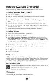
... to get into the USB port. 3. Insert the Windows 10/ Windows 11 installation disc/USB into your computer. If you turn off the AutoPlay feature from the Windows Control Panel, you easily optimize game settings and smoothly use content creation softwares. Installing OS, Drivers & MSI Center Please download and update the latest utilities and drivers at www.msi.com Installing Windows 10/ Windows 11 1. Press the Restart button on the computer case. 4. Installing Drivers 1. Click the Select to...
... to get into the USB port. 3. Insert the Windows 10/ Windows 11 installation disc/USB into your computer. If you turn off the AutoPlay feature from the Windows Control Panel, you easily optimize game settings and smoothly use content creation softwares. Installing OS, Drivers & MSI Center Please download and update the latest utilities and drivers at www.msi.com Installing Windows 10/ Windows 11 1. Press the Restart button on the computer case. 4. Installing Drivers 1. Click the Select to...

User Manual
Page 30
... BIOS Mode at the top of the new chipset capabilities. ⚠ Important The term BIOS in this motherboard supports only Windows 10/ Windows 11 64-bit operating system. ∙ Older graphics card - Press Delete key when the Press DEL key to enter Setup Menu, F11 to CSM mode during the boot process. 3. new devices may display a warning message There is compatible with UEFI (Unified Extensible Firmware Interface) architecture. If you use CPU with integrated graphics for hard drive...
... BIOS Mode at the top of the new chipset capabilities. ⚠ Important The term BIOS in this motherboard supports only Windows 10/ Windows 11 64-bit operating system. ∙ Older graphics card - Press Delete key when the Press DEL key to enter Setup Menu, F11 to CSM mode during the boot process. 3. new devices may display a warning message There is compatible with UEFI (Unified Extensible Firmware Interface) architecture. If you use CPU with integrated graphics for hard drive...

User Manual
Page 31
... more instructions on setting up the BIOS, please refer to http://download.msi.com/manual/mb/Intel600BIOS.pdf or scan the QR code to avoid possible system damage or failure booting unless you are familiar with BIOS. ⚠ Important ∙ BIOS items are regularly updated for reference only. Function key F1: General Help list F2: Add/ Remove a favorite item F3: Enter Favorites menu F4: Enter CPU Specifications menu F5: Enter Memory-Z menu F6: Load optimized defaults F7: Switch...
... more instructions on setting up the BIOS, please refer to http://download.msi.com/manual/mb/Intel600BIOS.pdf or scan the QR code to avoid possible system damage or failure booting unless you are familiar with BIOS. ⚠ Important ∙ BIOS items are regularly updated for reference only. Function key F1: General Help list F2: Add/ Remove a favorite item F3: Enter Favorites menu F4: Enter CPU Specifications menu F5: Enter Memory-Z menu F6: Load optimized defaults F7: Switch...

User Manual
Page 32
... might need to restore the default BIOS settings to solve certain problems. There are several ways to reset BIOS: ∙ Go to BIOS and press F6 to load optimized defaults. ∙ Short the Clear CMOS jumper on the motherboard. ⚠ Important Be sure the computer is 100% completed, the system will reboot automatically. 30 Updating BIOS Updating BIOS with M-FLASH Before updating: Please download the latest BIOS file that contains the update file into the USB flash drive.
... might need to restore the default BIOS settings to solve certain problems. There are several ways to reset BIOS: ∙ Go to BIOS and press F6 to load optimized defaults. ∙ Short the Clear CMOS jumper on the motherboard. ⚠ Important Be sure the computer is 100% completed, the system will reboot automatically. 30 Updating BIOS Updating BIOS with M-FLASH Before updating: Please download the latest BIOS file that contains the update file into the USB flash drive.

User Manual
Page 167
特殊功能 MSI Center RGB LED True Color • Live Update MSI Companion 网络 • 2.5G LAN M.2 7W/mK MOSFET LED RAINBOW/RGB 性能 • Lightning Gen 4 (M.2/PCIE Game Boost USB 3.2 Gen 2 10G • 前置 USB Type-C • 2 PCB设计 防护 • PCI-E 体验 • MSI Center BIOS • 简易 M.2 CPU LED LED 灯 • App 播放器 8
特殊功能 MSI Center RGB LED True Color • Live Update MSI Companion 网络 • 2.5G LAN M.2 7W/mK MOSFET LED RAINBOW/RGB 性能 • Lightning Gen 4 (M.2/PCIE Game Boost USB 3.2 Gen 2 10G • 前置 USB Type-C • 2 PCB设计 防护 • PCI-E 体验 • MSI Center BIOS • 简易 M.2 CPU LED LED 灯 • App 播放器 8
User Manual
Page 195
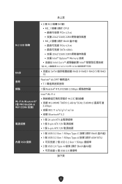
...; PRO B660M-A WIFI DDR4 配置) 電源接頭 內建 USB 接頭 ∙ 2 個 M.2 插槽 (M 鍵) • M2_1 CPU PCIe 4.0 x4 • 支援 2242/ 2260/ 2280 M2_2 B660 PCIe 4.0 x4 SATA 6Gb/s • 支援 2242/ 2260/ 2280 Intel® Optane™ Memory Intel Core Intel * 當 M2_2 M.2 SATA SSD 時,SATA8 SATA RAID 0、RAID1、RAID...
...; PRO B660M-A WIFI DDR4 配置) 電源接頭 內建 USB 接頭 ∙ 2 個 M.2 插槽 (M 鍵) • M2_1 CPU PCIe 4.0 x4 • 支援 2242/ 2260/ 2280 M2_2 B660 PCIe 4.0 x4 SATA 6Gb/s • 支援 2242/ 2260/ 2280 Intel® Optane™ Memory Intel Core Intel * 當 M2_2 M.2 SATA SSD 時,SATA8 SATA RAID 0、RAID1、RAID...
User Manual
Page 262
... spec. ∙ Version 1.2, 2022/5, Update component mark. ∙ Version 1.3, 2023/4, Update cover. ∙ Version 1.4, 2023/5, Update M.2 installation steps. All rights reserved. Technical Support If a problem arises with your place of their respective owners. Alternatively, please try the following help resources for further guidance. ∙ Visit the MSI website for technical guide, BIOS updates, driver updates, and other marks and names mentioned may be obtained from the user guide...
... spec. ∙ Version 1.2, 2022/5, Update component mark. ∙ Version 1.3, 2023/4, Update cover. ∙ Version 1.4, 2023/5, Update M.2 installation steps. All rights reserved. Technical Support If a problem arises with your place of their respective owners. Alternatively, please try the following help resources for further guidance. ∙ Visit the MSI website for technical guide, BIOS updates, driver updates, and other marks and names mentioned may be obtained from the user guide...


