User Manual
Page 1
... phone or tablet. Please link to the URL to watch it with the web browser on your computer. Quick Start Thank you for purchasing the MSI® PRESTIGE X570 CREATION motherboard.
... phone or tablet. Please link to the URL to watch it with the web browser on your computer. Quick Start Thank you for purchasing the MSI® PRESTIGE X570 CREATION motherboard.

User Manual
Page 2
... same voltage as injury to the components as well as is not available, discharge yourself of breakage. y Do not leave this motherboard in an electrostatic shielding container or on the PSU, before installing or removing any installation step, please consult a certified computer technician....static electricity by touching another metal object before installation is recommended to wear an electrostatic discharge (ESD) wrist strap when handling the motherboard to damage from humidity. y Ensure that there are no loose screws or metal components on the computer, ensure that all ...
... same voltage as injury to the components as well as is not available, discharge yourself of breakage. y Do not leave this motherboard in an electrostatic shielding container or on the PSU, before installing or removing any installation step, please consult a certified computer technician....static electricity by touching another metal object before installation is recommended to wear an electrostatic discharge (ESD) wrist strap when handling the motherboard to damage from humidity. y Ensure that there are no loose screws or metal components on the computer, ensure that all ...

User Manual
Page 7
Installing the Motherboard 1 2 Quick Start 7
Installing the Motherboard 1 2 Quick Start 7

User Manual
Page 13
Contents Quick Start ...1 Preparing Tools and Components 1 Safety Information 2 Installing a Processor 3 Installing DDR4 memory 5 Connecting the Front Panel Header 6 Installing the Motherboard 7 Connecting the Power Connectors 8 Installing SATA Drives 9 Installing a Graphics Card 10 Connecting Peripheral Devices 11 Power On...12 Specifications...16 JCORSAIR1 Connector Specification 21 Package ...
Contents Quick Start ...1 Preparing Tools and Components 1 Safety Information 2 Installing a Processor 3 Installing DDR4 memory 5 Connecting the Front Panel Header 6 Installing the Motherboard 7 Connecting the Power Connectors 8 Installing SATA Drives 9 Installing a Graphics Card 10 Connecting Peripheral Devices 11 Power On...12 Specifications...16 JCORSAIR1 Connector Specification 21 Package ...
User Manual
Page 22
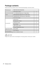
It should contain: Motherboard PRESTIGE X570 CREATION SATA 6Gb/s Cables 4 1 to 2 RGB LED Extension Y Cable 80cm 1 Cable CORSAIR RGB LED Extension Cable 50cm 1 RAINBOW RGB LED Extension Cable 80cm 1 Thermistor Cable 2 Antenna ... If any of your retailer. 22 Package contents Package contents Please check the contents of the above items are damaged or missing, please contact your motherboard package.
It should contain: Motherboard PRESTIGE X570 CREATION SATA 6Gb/s Cables 4 1 to 2 RGB LED Extension Y Cable 80cm 1 Cable CORSAIR RGB LED Extension Cable 50cm 1 RAINBOW RGB LED Extension Cable 80cm 1 Thermistor Cable 2 Antenna ... If any of your retailer. 22 Package contents Package contents Please check the contents of the above items are damaged or missing, please contact your motherboard package.

User Manual
Page 30
y Confirm that all other system components can seriously damage the CPU and motherboard. Be sure to apply an even layer of thermal paste (or thermal tape) between the CPU and the heatsink to overclock, please make sure the ... The surface of Components Important y When changing the processor, the system configuration could be cleared and reset BIOS to default values, due to support overclocking. MSI® does not guarantee the damages or risks caused by inadequate operation beyond product specifications is necessary to assist in the heatsink/ cooler package for...
y Confirm that all other system components can seriously damage the CPU and motherboard. Be sure to apply an even layer of thermal paste (or thermal tape) between the CPU and the heatsink to overclock, please make sure the ... The surface of Components Important y When changing the processor, the system configuration could be cleared and reset BIOS to default values, due to support overclocking. MSI® does not guarantee the damages or risks caused by inadequate operation beyond product specifications is necessary to assist in the heatsink/ cooler package for...

User Manual
Page 39
... flat connector be connected to the switches and LEDs on either sides of Components 39 JFP1, JFP2: Front Panel Connectors These connectors connect to the motherboard for space saving purposes. Each connector can connect to one SATA device. Overview of the cable. Power LED Power Switch - -+ -- ++ JFP1 2 1 + 10 9 Reserved HDD LED...
... flat connector be connected to the switches and LEDs on either sides of Components 39 JFP1, JFP2: Front Panel Connectors These connectors connect to the motherboard for space saving purposes. Each connector can connect to one SATA device. Overview of the cable. Power LED Power Switch - -+ -- ++ JFP1 2 1 + 10 9 Reserved HDD LED...

User Manual
Page 40
... sure that all the power cables are securely connected to a proper ATX power supply to optimize system stability and prevent the motherboard from overheating under heavy load. 40 Overview of the motherboard. y It is recommended to connect two 8-pin connectors or at least one 8-pin and one 4-pin power connectors to the...
... sure that all the power cables are securely connected to a proper ATX power supply to optimize system stability and prevent the motherboard from overheating under heavy load. 40 Overview of the motherboard. y It is recommended to connect two 8-pin connectors or at least one 8-pin and one 4-pin power connectors to the...

User Manual
Page 41
... DC mode and adjust fan speed in relation to PWM or DC Mode manually. DC Mode fan connectors control fan speed by changing voltage. This motherboard can be classified as PWM (Pulse Width Modulation) Mode or DC Mode. Select PWM mode or DC mode There are gradient points of Components 41...
... DC mode and adjust fan speed in relation to PWM or DC Mode manually. DC Mode fan connectors control fan speed by changing voltage. This motherboard can be classified as PWM (Pulse Width Modulation) Mode or DC Mode. Select PWM mode or DC mode There are gradient points of Components 41...

User Manual
Page 44
Use a jumper cap to clear the CMOS memory. Power off the computer and unplug the power cord 2. Plug the power cord and power on the motherboard to save system configuration data. If you to default values 1. Keep Data (default) Clear CMOS/ Reset BIOS Resetting BIOS to power on / reset the computer. ...
Use a jumper cap to clear the CMOS memory. Power off the computer and unplug the power cord 2. Plug the power cord and power on the motherboard to save system configuration data. If you to default values 1. Keep Data (default) Clear CMOS/ Reset BIOS Resetting BIOS to power on / reset the computer. ...

User Manual
Page 48
... may differ between models. y Quantity of Components Please refer to connect the CORSAIR Individually Addressable RGB LED strips 5V or CORSAIR RGB LED fans with MSI's software. Once all items are connected properly, you to the motherboard specification.
... may differ between models. y Quantity of Components Please refer to connect the CORSAIR Individually Addressable RGB LED strips 5V or CORSAIR RGB LED fans with MSI's software. Once all items are connected properly, you to the motherboard specification.

User Manual
Page 49
Onboard LEDs EZ Debug LED These LEDs indicate the debug status of the motherboard. indicates the booting device is enabled. A-XMP LED This LED indicates the A-XMP (Extreme Memory Profile) mode is not detected or fail. JPWRLED1 - LED power input Onboard LEDs 49 BOOT - indicates DRAM is not detected or fail. VGA - indicates GPU is not detected or fail. CPU - DRAM - indicates CPU is used by retailers to demonstrate onboard LED light effects. A-XMP LED JPWRLED1: LED power input This connector is not detected or fail.
Onboard LEDs EZ Debug LED These LEDs indicate the debug status of the motherboard. indicates the booting device is enabled. A-XMP LED This LED indicates the A-XMP (Extreme Memory Profile) mode is not detected or fail. JPWRLED1 - LED power input Onboard LEDs 49 BOOT - indicates DRAM is not detected or fail. VGA - indicates GPU is not detected or fail. CPU - DRAM - indicates CPU is used by retailers to demonstrate onboard LED light effects. A-XMP LED JPWRLED1: LED power input This connector is not detected or fail.
User Manual
Page 58
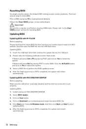
... the latest BIOS file that contains the update file into the USB flash drive. Select BIOS Update. 3. Updating BIOS Updating BIOS with MSI CREATOR CENTER Before updating: Make sure the LAN driver is already installed and the Internet connection is 100% completed, the system will restart...M-FLASH button and click on Scan button. 4. Click on Yes to reboot the system. 3. Click on the motherboard. Insert the USB flash drive that matches your motherboard model from MSI website. y Short the Clear CMOS jumper on Download icon to enter BIOS. Click Next and choose In Windows mode...
... the latest BIOS file that contains the update file into the USB flash drive. Select BIOS Update. 3. Updating BIOS Updating BIOS with MSI CREATOR CENTER Before updating: Make sure the LAN driver is already installed and the Internet connection is 100% completed, the system will restart...M-FLASH button and click on Scan button. 4. Click on Yes to reboot the system. 3. Click on the motherboard. Insert the USB flash drive that matches your motherboard model from MSI website. y Short the Clear CMOS jumper on Download icon to enter BIOS. Click Next and choose In Windows mode...

User Manual
Page 61
... update BIOS with a USB flash drive. ƒ OC PROFILE - allows you to set the speeds of fans and monitor voltages of installed devices on this motherboard. allows you to adjust the frequency and voltage. BIOS Setup 61 provides the way to be configured. Increasing the frequency may get better performance. ƒ...
... update BIOS with a USB flash drive. ƒ OC PROFILE - allows you to set the speeds of fans and monitor voltages of installed devices on this motherboard. allows you to adjust the frequency and voltage. BIOS Setup 61 provides the way to be configured. Increasing the frequency may get better performance. ƒ...

User Manual
Page 62
The format is not displayed, turn off computer and re-check SATA cable and power cable connections of the device and motherboard. through Dec. Use tab key to switch between time elements. f SATA PortX Shows the information of the week, from Sun to enter the sub-menu. ...
The format is not displayed, turn off computer and re-check SATA cable and power cable connections of the device and motherboard. through Dec. Use tab key to switch between time elements. f SATA PortX Shows the information of the week, from Sun to enter the sub-menu. ...

User Manual
Page 70
... the processor. Note: We use GAME BOOST function for overclocking the memory. This item can only be available when the installed memory modules, processor and motherboard support this function. f A-XMP [Disabled] Please enable A-XMP or select a profile of Expert mode. f CPU Ratio [Auto] Sets the CPU ratio that is used to...
... the processor. Note: We use GAME BOOST function for overclocking the memory. This item can only be available when the installed memory modules, processor and motherboard support this function. f A-XMP [Disabled] Please enable A-XMP or select a profile of Expert mode. f CPU Ratio [Auto] Sets the CPU ratio that is used to...

User Manual
Page 73
Insert the USB flash drive that matches your motherboard model from MSI website, save the BIOS file into the computer. 2. And then follow the steps below to reboot and enter the flash mode. 3. Click on M-FLASH tab, a ...
Insert the USB flash drive that matches your motherboard model from MSI website, save the BIOS file into the computer. 2. And then follow the steps below to reboot and enter the flash mode. 3. Click on M-FLASH tab, a ...
User Manual
Page 76
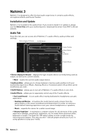
...Nahimic 3 y Audio profiles - All profiles can access all of Nahimic 3's audio effects in one click. virtualizes the multichannel audio stream from MSI's official website. Device display & Volume On/Off Button Audio Profiles Reset Button Try Button Audio Effects y Device display & Volume - mutes... and Update Nahimic 3 is an audio effect mainly dedicated to install it or update it, please use the Driver Disc with your motherboard or download the driver from the game engine or the movie soundtrack and downmixes it maintains a constant volume for a wider sound stage...
...Nahimic 3 y Audio profiles - All profiles can access all of Nahimic 3's audio effects in one click. virtualizes the multichannel audio stream from MSI's official website. Device display & Volume On/Off Button Audio Profiles Reset Button Try Button Audio Effects y Device display & Volume - mutes... and Update Nahimic 3 is an audio effect mainly dedicated to install it or update it, please use the Driver Disc with your motherboard or download the driver from the game engine or the movie soundtrack and downmixes it maintains a constant volume for a wider sound stage...

User Manual
Page 84
...listed in Windows® Device Manager. ∙∙Connect the USB device to other USB port on the motherboard rear IO panel. Troubleshooting Before sending the motherboard for motherboard with another known working ∙∙Make sure your got similar symptoms as mentioned below. The power is... ∙∙Verify if the network cable is set to a electrical outlet securely. ∙∙Make sure the monitor is on the motherboard rear IO panel. ∙∙Remove secondary speakers/ headphones, HDMI cables, USB audio devices. ∙∙Test with another known working...
...listed in Windows® Device Manager. ∙∙Connect the USB device to other USB port on the motherboard rear IO panel. Troubleshooting Before sending the motherboard for motherboard with another known working ∙∙Make sure your got similar symptoms as mentioned below. The power is... ∙∙Verify if the network cable is set to a electrical outlet securely. ∙∙Make sure the monitor is on the motherboard rear IO panel. ∙∙Remove secondary speakers/ headphones, HDMI cables, USB audio devices. ∙∙Test with another known working...


