User Guide
Page 1
... be used in a residential installation. However, there is connected. 4 Consult the dealer or an experienced radio/ television technician for help. power cord, if any interference received, including interference that interference will occur in order to part 15 of the FCC rules. Notice 2 Shielded interface cables and A.C. Micro-Star International MS-7222 This device complies with Part 15 of the measures listed...
... be used in a residential installation. However, there is connected. 4 Consult the dealer or an experienced radio/ television technician for help. power cord, if any interference received, including interference that interference will occur in order to part 15 of the FCC rules. Notice 2 Shielded interface cables and A.C. Micro-Star International MS-7222 This device complies with Part 15 of the measures listed...
User Guide
Page 3
... to the power inlet. 7. The equipment has dropped and damaged. - iii The openings on it work well or you can not step on the enclosure are for future reference. 3. Make sure the voltage of the following situations arises, get it . Replace only with the same or equivalent type recommended by service personnel: - Lay this User Manual for air...
... to the power inlet. 7. The equipment has dropped and damaged. - iii The openings on it work well or you can not step on the enclosure are for future reference. 3. Make sure the voltage of the following situations arises, get it . Replace only with the same or equivalent type recommended by service personnel: - Lay this User Manual for air...
User Guide
Page 7
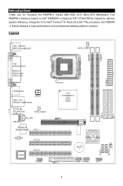
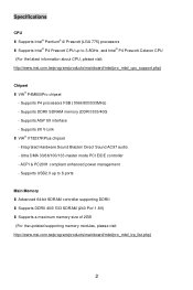
Introduction Thank you for optimal system efficiency. Designed to fit Intel® Pentium® 4/ Prescott (LGA 775) processor, the PM8PM -V Series delivers a high performance and professional desktop platform solution. Layout 1 The PM8PM-V Series is based on VIA® P4M800Pro chipset & VIA® VT8237RPlus chipset for choosing the PM8PM-V Series (MS-7222 v2.0) Micro-ATX Mainboard.
Introduction Thank you for optimal system efficiency. Designed to fit Intel® Pentium® 4/ Prescott (LGA 775) processor, the PM8PM -V Series delivers a high performance and professional desktop platform solution. Layout 1 The PM8PM-V Series is based on VIA® P4M800Pro chipset & VIA® VT8237RPlus chipset for choosing the PM8PM-V Series (MS-7222 v2.0) Micro-ATX Mainboard.
User Guide
Page 8
... to 8 ports Main Memory l Advanced 64-bit SDRAM controller supporting DDRII l Supports DDRII 400/ 533 SDRAM (240 Pin/ 1.8V) l Supports a maximum memory size of 2GB (For the updated supporting memory modules, please visit: http://www.msi.com.tw/program/products/mainboard/mbd/pro_mbd_trp_list.php) 2 Supports AGP 8X interface - ACPI & PC2001 compliant enhanced power management - Ultra DMA 33/66/100/133 master mode PCI EIDE controller - Supports 8X V-Link l VIA® VT8237RPlus chipset - Supports P4 processors FSB...
... to 8 ports Main Memory l Advanced 64-bit SDRAM controller supporting DDRII l Supports DDRII 400/ 533 SDRAM (240 Pin/ 1.8V) l Supports a maximum memory size of 2GB (For the updated supporting memory modules, please visit: http://www.msi.com.tw/program/products/mainboard/mbd/pro_mbd_trp_list.php) 2 Supports AGP 8X interface - ACPI & PC2001 compliant enhanced power management - Ultra DMA 33/66/100/133 master mode PCI EIDE controller - Supports 8X V-Link l VIA® VT8237RPlus chipset - Supports P4 processors FSB...
User Guide
Page 9
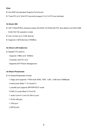
... l One AGP (Accelerated Graphics Port) 8x slot l Three PCI v2.2 32-bit PCI bus slots (support 3.3v/ 5v PCI bus interface) On-Board IDE l VIA® VT8237RPlus chipset provides IDE HDD/ CD-ROM with 360K, 720K, 1.2M, 1.44M and 2.88Mbytes - 2 serial ports (Rear*1/ On-board*1) - 1 parallel port supports SPP/EPP/ECP mode - 8 USB 2.0 ports (Rear*4/ Front*4) - 1 audio (Line-In/ Line-Out/ Mic-In) port - 1 RJ45 LAN jack - 1 VGA port - 2 SATA ports 3 Supports 10Mb/s and 100Mb/s - Supports ACPI Power Management On-Board Peripherals l On-Board Peripherals include: - 1 floppy port supports 1 FDDs with...
... l One AGP (Accelerated Graphics Port) 8x slot l Three PCI v2.2 32-bit PCI bus slots (support 3.3v/ 5v PCI bus interface) On-Board IDE l VIA® VT8237RPlus chipset provides IDE HDD/ CD-ROM with 360K, 720K, 1.2M, 1.44M and 2.88Mbytes - 2 serial ports (Rear*1/ On-board*1) - 1 parallel port supports SPP/EPP/ECP mode - 8 USB 2.0 ports (Rear*4/ Front*4) - 1 audio (Line-In/ Line-Out/ Mic-In) port - 1 RJ45 LAN jack - 1 VGA port - 2 SATA ports 3 Supports 10Mb/s and 100Mb/s - Supports ACPI Power Management On-Board Peripherals l On-Board Peripherals include: - 1 floppy port supports 1 FDDs with...
User Guide
Page 10
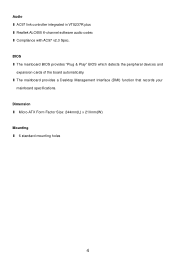
l The mainboard provides a Desktop Management Interface (DMI) function that records your mainboard specifications. Audio l AC97 link controller integrated in VT8237R plus l Realtek ALC655 6-channel software audio codec l Compliance with AC97 v2.3 Spec. Dimension l Micro-ATX Form Factor Size: 244mm(L) x 210mm(W) Mounting l 6 standard mounting holes 4 BIOS l The mainboard BIOS provides "Plug & Play" BIOS which detects the peripheral devices and expansion cards of the board automatically.
l The mainboard provides a Desktop Management Interface (DMI) function that records your mainboard specifications. Audio l AC97 link controller integrated in VT8237R plus l Realtek ALC655 6-channel software audio codec l Compliance with AC97 v2.3 Spec. Dimension l Micro-ATX Form Factor Size: 244mm(L) x 210mm(W) Mounting l 6 standard mounting holes 4 BIOS l The mainboard BIOS provides "Plug & Play" BIOS which detects the peripheral devices and expansion cards of the board automatically.
User Guide
Page 11
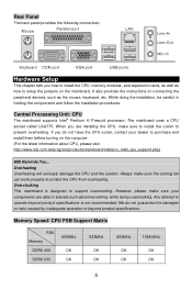
... attempt to operate beyond product specifications. Memory Speed/ CPU FSB Support Matrix FSB Memory DDRII 400 DDRII 533 400MHz OK OK 533MHz OK OK 800MHz OK OK 1066 MHz OK OK 5 While doing overclocking. Rear Panel The back panel provides the following connectors: Hardware Setup This chapter tells you how to install the CPU, memory modules, and expansion cards, as well as the mouse, keyboard, etc.
... attempt to operate beyond product specifications. Memory Speed/ CPU FSB Support Matrix FSB Memory DDRII 400 DDRII 533 400MHz OK OK 533MHz OK OK 800MHz OK OK 1066 MHz OK OK 5 While doing overclocking. Rear Panel The back panel provides the following connectors: Hardware Setup This chapter tells you how to install the CPU, memory modules, and expansion cards, as well as the mouse, keyboard, etc.
User Guide
Page 13
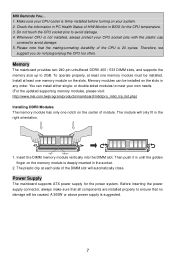
... on your system. 2. Power Supply The mainboard supports ATX power supply for the CPU temperature. 3. MSI Reminds You... 1. Whenever CPU is 20 cycles. Memory The mainboard provides two 240-pin unbuffered DDRII 400 / 533 DIMM slots, and supports the memory size up to avoid damage. 4. Volt Notch 1. Make sure your CPU cooler is firmly installed before turning on the memory module is suggested. 7 Check the information in BIOS for the power system. To operate...
... on your system. 2. Power Supply The mainboard supports ATX power supply for the CPU temperature. 3. MSI Reminds You... 1. Whenever CPU is 20 cycles. Memory The mainboard provides two 240-pin unbuffered DDRII 400 / 533 DIMM slots, and supports the memory size up to avoid damage. 4. Volt Notch 1. Make sure your CPU cooler is firmly installed before turning on the memory module is suggested. 7 Check the information in BIOS for the power system. To operate...
User Guide
Page 14
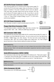
... hard disk vendors for CD-ROM audio connector. There is used to provide power to connect an ATX 24-pin power supply. You can connect up to avoid wrong installation. You must configure the second drive to 1 hard disk device. These ports support 1st generation Serial ATA data rates of the power supply is for jumper setting instructions. MSI Reminds You... IDE Connector: IDE1/ IDE2 The mainboard has dual Ultra DMA 33/66/100/133 controller that supports 360K, 720K, 1.2M, 1.44M and 2.88M floppy disk types...
... hard disk vendors for CD-ROM audio connector. There is used to provide power to connect an ATX 24-pin power supply. You can connect up to avoid wrong installation. You must configure the second drive to 1 hard disk device. These ports support 1st generation Serial ATA data rates of the power supply is for jumper setting instructions. MSI Reminds You... IDE Connector: IDE1/ IDE2 The mainboard has dual Ultra DMA 33/66/100/133 controller that supports 360K, 720K, 1.2M, 1.44M and 2.88M floppy disk types...
User Guide
Page 15
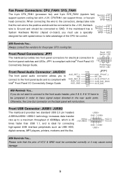
....0 technology increases data transfer rate up to the rear audio ports. When connecting the wire to the connectors, always take advantage of 480Mbps, which is 40 times faster than USB 1.1, and is Ground and should be connected to 9 1 the front panel switches and LEDs. Front USB Connector: JUSB1/ JUSB2 The mainboard provides two standard USB 2.0 pin headers JUSB1&JUSB2. Fan Power Connectors: CPU_FAN1/ SYS_FAN1 The 4-pin CPU_FAN1 (processor fan) and 3-pin SYS_FAN1 (system fan) support system...
....0 technology increases data transfer rate up to the rear audio ports. When connecting the wire to the connectors, always take advantage of 480Mbps, which is 40 times faster than USB 1.1, and is Ground and should be connected to 9 1 the front panel switches and LEDs. Front USB Connector: JUSB1/ JUSB2 The mainboard provides two standard USB 2.0 pin headers JUSB1&JUSB2. Fan Power Connectors: CPU_FAN1/ SYS_FAN1 The 4-pin CPU_FAN1 (processor fan) and 3-pin SYS_FAN1 (system fan) support system...
User Guide
Page 16
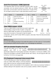
... a CMOS RAM on board that has a power supply from external battery to meet your needs. Both are 16550A high speed communication ports that you want to clear the system Keep Data Clear Data configuration, use the JCLR1 (Clear CMOS Jumper) to directly access main memory. it is an interface specification designed for the graphics controller to clear data. AGP is turned on ; Follow the instructions below to 1-2 pin position. Serial Port Connector: COM2 (Optional) The mainboard offers one 9-pin male DIN connector COM...
... a CMOS RAM on board that has a power supply from external battery to meet your needs. Both are 16550A high speed communication ports that you want to clear the system Keep Data Clear Data configuration, use the JCLR1 (Clear CMOS Jumper) to directly access main memory. it is an interface specification designed for the graphics controller to clear data. AGP is turned on ; Follow the instructions below to 1-2 pin position. Serial Port Connector: COM2 (Optional) The mainboard offers one 9-pin male DIN connector COM...
User Guide
Page 18
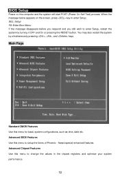
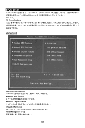
BIOS Setup Power on the screen, press key to enter Setup. Advanced Chipset Features Use this menu to setup the items of Phoenix - You may also restart the system by turning it OFF and On or pressing the RESET button. Award special enhanced features. Main Page Standard CMOS Features Use this menu to change the values in the chipset registers and optimize your system performance. 12 When the message below appears on...
BIOS Setup Power on the screen, press key to enter Setup. Advanced Chipset Features Use this menu to setup the items of Phoenix - You may also restart the system by turning it OFF and On or pressing the RESET button. Award special enhanced features. Main Page Standard CMOS Features Use this menu to change the values in the chipset registers and optimize your system performance. 12 When the message below appears on...
User Guide
Page 19
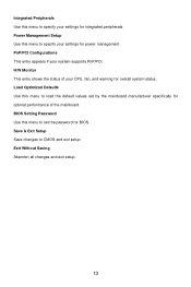
PnP/PCI Configurations This entry appears if your CPU, fan, and warning for overall system status. Integrated Peripherals Use this menu to load the default values set the password for BIOS. Load Optimized Defaults Use this menu to specify your settings for power management. Power Management Setup Use this menu to specify your settings for optimal performance of your system supports PnP/PCI. BIOS Setting Password Use this menu to set by the mainboard manufacturer specifically for integrated peripherals. H/W Monitor This entry shows the...
PnP/PCI Configurations This entry appears if your CPU, fan, and warning for overall system status. Integrated Peripherals Use this menu to load the default values set the password for BIOS. Load Optimized Defaults Use this menu to specify your settings for power management. Power Management Setup Use this menu to specify your settings for optimal performance of your system supports PnP/PCI. BIOS Setting Password Use this menu to set by the mainboard manufacturer specifically for integrated peripherals. H/W Monitor This entry shows the...
User Guide
Page 20
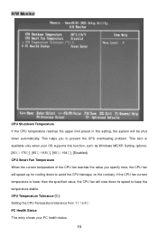
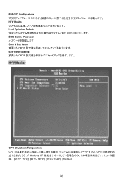
CPU Smart Fan Temperature When the current temperature of the CPU fan reaches the value you to keep the temperature stable. This item is lower than the specified value, the CPU fan will be shut down its speed to prevent the CPU overheating problem. Setting options: [80℃/ 176℃], [85℃/ 185℃], [90℃/ 194℃], [Disabled]. CPU Temperature Tolerance (℃) Setting the CPU Temperature tolerance from 1℃ to avoid...
CPU Smart Fan Temperature When the current temperature of the CPU fan reaches the value you to keep the temperature stable. This item is lower than the specified value, the CPU fan will be shut down its speed to prevent the CPU overheating problem. Setting options: [80℃/ 176℃], [85℃/ 185℃], [90℃/ 194℃], [Disabled]. CPU Temperature Tolerance (℃) Setting the CPU Temperature tolerance from 1℃ to avoid...

User Guide
Page 75
Save & Exit Setup CMOS Setup 程序. CPU Smart Fan Temperature CPU CPU CPU CPU CPU CPU CPU CPU Temperature Tolerance (CPU CPU 1℃到 5℃. 69 Exit Without Saving CMOS Setup 程序. 硬件监视 CPU Shutdown Temperature(CPU CPU CPU Windows ME/XP 80℃/ 176℃], [85℃/ 185℃], [90℃/ 194℃], [Disabled]. H/W Monitor CPU Load Optimized Defaults BIOS BIOS Setting Password(BIOS BIOS 的密码.
Save & Exit Setup CMOS Setup 程序. CPU Smart Fan Temperature CPU CPU CPU CPU CPU CPU CPU CPU Temperature Tolerance (CPU CPU 1℃到 5℃. 69 Exit Without Saving CMOS Setup 程序. 硬件监视 CPU Shutdown Temperature(CPU CPU CPU Windows ME/XP 80℃/ 176℃], [85℃/ 185℃], [90℃/ 194℃], [Disabled]. H/W Monitor CPU Load Optimized Defaults BIOS BIOS Setting Password(BIOS BIOS 的密码.
User Guide
Page 87
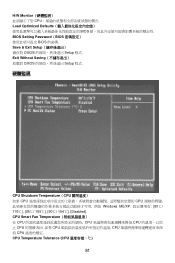
Exit Without Saving CMOS Setup 程式. 硬體監視 CPU Shutdown Temperature(CPU CPU CPU Windows ME/XP 80℃/ 176℃], [85℃/ 185℃], [90℃/ 194℃], [Disabled]. CPU Smart Fan Temperature CPU CPU CPU CPU CPU CPU CPU CPU Temperature Tolerance (CPU 81 Save & Exit Setup CMOS Setup 程式. H/W Monitor CPU Load Optimized Defaults BIOS BIOS Setting Password(BIOS BIOS 的密碼.
Exit Without Saving CMOS Setup 程式. 硬體監視 CPU Shutdown Temperature(CPU CPU CPU Windows ME/XP 80℃/ 176℃], [85℃/ 185℃], [90℃/ 194℃], [Disabled]. CPU Smart Fan Temperature CPU CPU CPU CPU CPU CPU CPU CPU Temperature Tolerance (CPU 81 Save & Exit Setup CMOS Setup 程式. H/W Monitor CPU Load Optimized Defaults BIOS BIOS Setting Password(BIOS BIOS 的密碼.
User Guide
Page 94
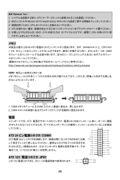
MSI Reminds You... 1 CPU 2. BIOS には H/W Monitor の PC Health Status 中の CPU 3 CPU 4. DIMM DIMM 2. CPU CPU 5 CPU 20 CPU メモリ 2GB 240 2 DDR DDRII 400 / 533 DIMM http://www.msi.com.tw/program/products/mainboard/mbd/pro_mbd_trp_list.php) DDRII Volt Notch 1. DIMM 電源 ATX 12 24 NC ATX 24 CONN1 ATX 電源 24 +12V +12V 5VSB PWR OK...
MSI Reminds You... 1 CPU 2. BIOS には H/W Monitor の PC Health Status 中の CPU 3 CPU 4. DIMM DIMM 2. CPU CPU 5 CPU 20 CPU メモリ 2GB 240 2 DDR DDRII 400 / 533 DIMM http://www.msi.com.tw/program/products/mainboard/mbd/pro_mbd_trp_list.php) DDRII Volt Notch 1. DIMM 電源 ATX 12 24 NC ATX 24 CONN1 ATX 電源 24 +12V +12V 5VSB PWR OK...
User Guide
Page 96
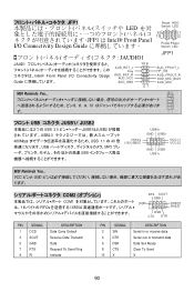
... Panel I/O Connectivity Design Guide AUD_RET_L Key AUD_RET_R AUD_VCC AUD_GND 10 9 21 Reset HDD Switch LED 9 1 10 2 PowerPower Switch LED JFP1 AUD_FPOUT_L HP_ON AUD_FPOUT_R AUD_MIC_BIAS AUD_MIC MSI Reminds You 10 USB JUSB1/ JUSB2 USB 2.0 JUSB1&JUSB2 USB2.0 480Mbps USB 1.1 の 40 USB MP3 USB (9)Key (10)USB0C USB0+ GND USB0- VCC ピンと GND COM2 COM1 FIFOs 16550A RTS SOUT GND [9]RI SIN[2] DSR CTS DTR PIN SIGNAL...
... Panel I/O Connectivity Design Guide AUD_RET_L Key AUD_RET_R AUD_VCC AUD_GND 10 9 21 Reset HDD Switch LED 9 1 10 2 PowerPower Switch LED JFP1 AUD_FPOUT_L HP_ON AUD_FPOUT_R AUD_MIC_BIAS AUD_MIC MSI Reminds You 10 USB JUSB1/ JUSB2 USB 2.0 JUSB1&JUSB2 USB2.0 480Mbps USB 1.1 の 40 USB MP3 USB (9)Key (10)USB0C USB0+ GND USB0- VCC ピンと GND COM2 COM1 FIFOs 16550A RTS SOUT GND [9]RI SIN[2] DSR CTS DTR PIN SIGNAL...
User Guide
Page 98
BIOS Setup POST (Power On Self Test DEL DEL: Setup F8: Enter Boot Menu , , and
BIOS Setup POST (Power On Self Test DEL DEL: Setup F8: Enter Boot Menu , , and
User Guide
Page 99
PnP/PCI Configurations PCI H/W Monitor Load Optimized Defaults BIOS BIOS Setting Password Save & Exit Setup CMOS Exit Without Saving CMOS H/W Monitor CPU Shutdown Temperature CPU CPU OS が Windows XP 80℃/ 176℃], [85℃/ 185℃], [90℃/ 194℃], [Disabled]. 93
PnP/PCI Configurations PCI H/W Monitor Load Optimized Defaults BIOS BIOS Setting Password Save & Exit Setup CMOS Exit Without Saving CMOS H/W Monitor CPU Shutdown Temperature CPU CPU OS が Windows XP 80℃/ 176℃], [85℃/ 185℃], [90℃/ 194℃], [Disabled]. 93


