
User Guide
Page 8
...Specifications 1-2 Mainboard Layout 1-4 Packing Checklist 1-5 Chapter 2 Hardware Setup 2-1 Quick Components Guide 2-2 CPU (Central Processing Unit 2-3 Memory ...2-7 Power Supply ...2-9 Back Panel ...2-12 Connectors ...2-14 Button ...2-22 Slots ...2-23 Chapter 3 BIOS Setup 3-1 Entering Setup ...3-2 The Main Menu ...3-4 ...Standard CMOS Features 3-6 Advanced BIOS Features 3-9 Integrated Peripherals 3-12 Power Management Setup 3-15 PNP/PCI Configurations 3-18 H/W Monitor ...3-20 Cell Menu ...3-21 Load Fail-Safe/ Optimized Defaults ...
...Specifications 1-2 Mainboard Layout 1-4 Packing Checklist 1-5 Chapter 2 Hardware Setup 2-1 Quick Components Guide 2-2 CPU (Central Processing Unit 2-3 Memory ...2-7 Power Supply ...2-9 Back Panel ...2-12 Connectors ...2-14 Button ...2-22 Slots ...2-23 Chapter 3 BIOS Setup 3-1 Entering Setup ...3-2 The Main Menu ...3-4 ...Standard CMOS Features 3-6 Advanced BIOS Features 3-9 Integrated Peripherals 3-12 Power Management Setup 3-15 PNP/PCI Configurations 3-18 H/W Monitor ...3-20 Cell Menu ...3-21 Load Fail-Safe/ Optimized Defaults ...
User Guide
Page 17
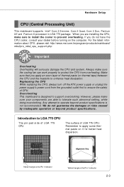
...beyond product specifications is the Pin 1 indicator 2-3 Replaceing the CPU While replacing the CPU, always turn off the ATX power supply or unplug the power supply's power cord from overheating. Any attempt to operate beyond product specifications. Always make sure the cooling fan can work properly ... in LGA 775 package. The surface of LGA 775 CPU. For the latest information about CPU, please visit http://www.msi.com.tw/program/products/mainboard/ mbd/pro_mbd_cpu_support.php Important Overheating Overheating will seriously damage the CPU and system. Make sure that...
...beyond product specifications is the Pin 1 indicator 2-3 Replaceing the CPU While replacing the CPU, always turn off the ATX power supply or unplug the power supply's power cord from overheating. Any attempt to operate beyond product specifications. Always make sure the cooling fan can work properly ... in LGA 775 package. The surface of LGA 775 CPU. For the latest information about CPU, please visit http://www.msi.com.tw/program/products/mainboard/ mbd/pro_mbd_cpu_support.php Important Overheating Overheating will seriously damage the CPU and system. Make sure that...

User Guide
Page 24
... GND pin 13 pin 12 ATX 12V Power Connector: JPW1 This power connector is highly recommended for system stability. 2-10 MS-7350 Mainboard Power Supply ATX 24-Pin Power Connector: ATX1 This connector allows you like to use the 20-pin ATX power supply as you to connect an ATX 24-pin power supply. To connect the ATX 24-pin power supply, make sure the plug...
... GND pin 13 pin 12 ATX 12V Power Connector: JPW1 This power connector is highly recommended for system stability. 2-10 MS-7350 Mainboard Power Supply ATX 24-Pin Power Connector: ATX1 This connector allows you like to use the 20-pin ATX power supply as you to connect an ATX 24-pin power supply. To connect the ATX 24-pin power supply, make sure the plug...

User Guide
Page 36
Make sure that has a power supply from external battery to clear the data. SW1 Important 1. Clear CMOS Button: SW1 There is charged. MS-7350 Mainboard Button This motherboard provides the following button for you power off the system before clearing CMOS data. 2. The indicator LED ...beside the button and will explain how to change your motherboard's function through the use the button to clear ...
Make sure that has a power supply from external battery to clear the data. SW1 Important 1. Clear CMOS Button: SW1 There is charged. MS-7350 Mainboard Button This motherboard provides the following button for you power off the system before clearing CMOS data. 2. The indicator LED ...beside the button and will explain how to change your motherboard's function through the use the button to clear ...

User Guide
Page 38
...system before removing the SLI switch card. 2. Pull the clasp. Important Fig.2 Make sure that you unplug the power supply first. Press down the SLI switch card untill the clsaps on the sides of the NV SLI connector to loosen the SLI switch card (refer to the other side (SLI mode side) and... insert it over to fig.2). Remove the SLI switch card. Before installing or...
...system before removing the SLI switch card. 2. Pull the clasp. Important Fig.2 Make sure that you unplug the power supply first. Press down the SLI switch card untill the clsaps on the sides of the NV SLI connector to loosen the SLI switch card (refer to the other side (SLI mode side) and... insert it over to fig.2). Remove the SLI switch card. Before installing or...

