
User Guide
Page 4
... any, must accept any interference received, including interference that may cause harmful interference to radio communications. Notice 2 Shielded interface cables and A.C. iv Micro-Star International MS-7350 This device complies with the emission limits. FCC-B Radio Frequency Interference Statement T h is encouraged to try to correct the interference by the party responsible for...
... any, must accept any interference received, including interference that may cause harmful interference to radio communications. Notice 2 Shielded interface cables and A.C. iv Micro-Star International MS-7350 This device complies with the emission limits. FCC-B Radio Frequency Interference Statement T h is encouraged to try to correct the interference by the party responsible for...

User Guide
Page 10
Getting Started Chapter 1 Getting Started Thank you for optimal system efficiency. The P6N SLI Platinum Series mainboards are based on nVidia® nForce 650i SLI chipsets for choosing the P6N SLI Platinum Series (MS-7350 v1.X) ATX mainboard. Designed to fit the advanced Intel® Core 2 Extreme, Core 2 Quad, Core 2 Duo, Pentium XE and Pentium D processor, the P6N SLI Platinum Series deliver a high performance and professional desktop platform solution. 1-1
Getting Started Chapter 1 Getting Started Thank you for optimal system efficiency. The P6N SLI Platinum Series mainboards are based on nVidia® nForce 650i SLI chipsets for choosing the P6N SLI Platinum Series (MS-7350 v1.X) ATX mainboard. Designed to fit the advanced Intel® Core 2 Extreme, Core 2 Quad, Core 2 Duo, Pentium XE and Pentium D processor, the P6N SLI Platinum Series deliver a high performance and professional desktop platform solution. 1-1

User Guide
Page 11
...66/100/133 mode and PIO, Bus Master operation m ode - MS-7350 Mainboard Mainboard Specifications Processor Support - Supports Intel® SpeedStep Technology (EIST) (For the latest information about CPU, please visit http://www.msi. South Bridge: nVidia® nForce 430i (MCP51) Memory Support ... components, please visit http:/ / w w w .ms i . Transfer rate is up to 300 MB/s - 1 eSATA port by Realtek® RTL8211BL IEEE 1394 - Supports Intel® EIST Technology - Chip integrated by nForce 430i - North Bridge: nVidia® nForce 650i SLI (C55) - c om. Intel® Core 2...
...66/100/133 mode and PIO, Bus Master operation m ode - MS-7350 Mainboard Mainboard Specifications Processor Support - Supports Intel® SpeedStep Technology (EIST) (For the latest information about CPU, please visit http://www.msi. South Bridge: nVidia® nForce 430i (MCP51) Memory Support ... components, please visit http:/ / w w w .ms i . Transfer rate is up to 300 MB/s - 1 eSATA port by Realtek® RTL8211BL IEEE 1394 - Supports Intel® EIST Technology - Chip integrated by nForce 430i - North Bridge: nVidia® nForce 650i SLI (C55) - c om. Intel® Core 2...

User Guide
Page 13
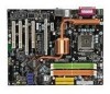
MS-7350 Mainboard Mainboard Layout Top : mouse Bottom: keyboard CP UFA N1 ATX1 DIMM1 DIMM3 DIMM2 DIMM4 IDE2 IDE1 SATA1 SATA2 SATA3 SATA4 USB ports T: LAN B: USB ports T: Li ne- Out B:Mic T: RS -Out M:CS-Out B:Optical S/PDIF Out LAN Chip I/O Chip JPW1 Nv idi a Nforce 650I SLI PCI_E1 SYSFAN1 PCI_E2 PCI1 JCI1 PCI_E4 PCI_E3 SYSFAN3 Nvidia Nforce 430I BATT + SW1 Co dec PCI2 PCI3 1394 Ch ip JFP1 JUSB2 JFP2 JCD1 JAU D1 SPDO1 JCOM1 SYSFAN2 J1394_1 JD B1 FDD 1 JUSB1 P6N SLI Platinum Series (MS-7350 v1.X) ATX Mainboard 1-4 In M:L ine-
MS-7350 Mainboard Mainboard Layout Top : mouse Bottom: keyboard CP UFA N1 ATX1 DIMM1 DIMM3 DIMM2 DIMM4 IDE2 IDE1 SATA1 SATA2 SATA3 SATA4 USB ports T: LAN B: USB ports T: Li ne- Out B:Mic T: RS -Out M:CS-Out B:Optical S/PDIF Out LAN Chip I/O Chip JPW1 Nv idi a Nforce 650I SLI PCI_E1 SYSFAN1 PCI_E2 PCI1 JCI1 PCI_E4 PCI_E3 SYSFAN3 Nvidia Nforce 430I BATT + SW1 Co dec PCI2 PCI3 1394 Ch ip JFP1 JUSB2 JFP2 JCD1 JAU D1 SPDO1 JCOM1 SYSFAN2 J1394_1 JD B1 FDD 1 JUSB1 P6N SLI Platinum Series (MS-7350 v1.X) ATX Mainboard 1-4 In M:L ine-

User Guide
Page 18
MS-7350 Mainboard CPU & Cooler Installation W hen you install the CPU, always cover it to apply some thermal paste on CPU before turning on your CPU & mainboard. 1. ...
MS-7350 Mainboard CPU & Cooler Installation W hen you install the CPU, always cover it to apply some thermal paste on CPU before turning on your CPU & mainboard. 1. ...

User Guide
Page 20
.... Align the holes on it) to the correct direction marked on the mainboard with the plastic cap covered (shown in Figure 1) to fasten the cooler. MS-7350 Mainboard 9. Turn over the mainboard to confirm that the clip-ends are for demonstration of your CPU socket pin with the heatsink. Mainboard photos shown...
.... Align the holes on it) to the correct direction marked on the mainboard with the plastic cap covered (shown in Figure 1) to fasten the cooler. MS-7350 Mainboard 9. Turn over the mainboard to confirm that the clip-ends are for demonstration of your CPU socket pin with the heatsink. Mainboard photos shown...

User Guide
Page 22
... 16GB) when each side of the same type and density in different channel DIMM slots. - DDR2 memory modules are not interchangeable with a 2GB memory module. 2-8 MS-7350 Mainboard Installing DDR2 Modules 1. Then push it in until the golden finger on the center and will automatically close. Volt Notch Important - Important You can...
... 16GB) when each side of the same type and density in different channel DIMM slots. - DDR2 memory modules are not interchangeable with a 2GB memory module. 2-8 MS-7350 Mainboard Installing DDR2 Modules 1. Then push it in until the golden finger on the center and will automatically close. Volt Notch Important - Important You can...

User Guide
Page 24
... 19 GND 8 PW R OK 20 Res 9 5VSB 21 +5V 10 +12V 22 +5V 11 +12V 23 +5V 12 +3.3V 24 GND pin 13 pin 12 ATX 12V Power Connector: JPW1 This power connector is highly recommended for system stability. 2-10 JPW1 8 5 4 1 Pin Definition PIN SIGNAL PIN SIGNAL 1 GND 2 GND 3 GND 4 GND... a foolproof design on pin 11, 12, 23 & 24 to ensure stable operation of 450 watts (and above) is used to provide power to the CPU. MS-7350 Mainboard Power Supply ATX 24-Pin Power Connector: ATX1 This connector allows you to the image at the right hand).
... 19 GND 8 PW R OK 20 Res 9 5VSB 21 +5V 10 +12V 22 +5V 11 +12V 23 +5V 12 +3.3V 24 GND pin 13 pin 12 ATX 12V Power Connector: JPW1 This power connector is highly recommended for system stability. 2-10 JPW1 8 5 4 1 Pin Definition PIN SIGNAL PIN SIGNAL 1 GND 2 GND 3 GND 4 GND... a foolproof design on pin 11, 12, 23 & 24 to ensure stable operation of 450 watts (and above) is used to provide power to the CPU. MS-7350 Mainboard Power Supply ATX 24-Pin Power Connector: ATX1 This connector allows you to the image at the right hand).

User Guide
Page 26
... standard RJ-45 LAN jack is provided for a PS/2® mouse/keyboard. On 1000 Mbit/sec data rate is for digital audio transmission to it. MS-7350 Mainboard Back Panel Mouse Parallel Port USB Port LAN Line-In RS-Out Line-Out CS-Out Keyboard eSATA Port 1394 Coaxial Port S/PDIF-Out...
... standard RJ-45 LAN jack is provided for a PS/2® mouse/keyboard. On 1000 Mbit/sec data rate is for digital audio transmission to it. MS-7350 Mainboard Back Panel Mouse Parallel Port USB Port LAN Line-In RS-Out Line-Out CS-Out Keyboard eSATA Port 1394 Coaxial Port S/PDIF-Out...

User Guide
Page 28
MS-7350 Mainboard Connectors Floppy Disk Drive Connector: FDD1 This connector supports 360KB, 720KB, 1.2MB, 1.44MB or 2.88MB floppy disk drive. FDD1 IDE Connector: IDE1 / IDE2 This ...
MS-7350 Mainboard Connectors Floppy Disk Drive Connector: FDD1 This connector supports 360KB, 720KB, 1.2MB, 1.44MB or 2.88MB floppy disk drive. FDD1 IDE Connector: IDE1 / IDE2 This ...

User Guide
Page 30
... the positive and should be activated. If the mainboard has a System Hardware Monitor chipset on the screen. The system will be connected to the +12V; MS-7350 Mainboard Fan Power Connectors: CPUFAN, SYSFAN1, SYSFAN2, SYSFAN3 The fan power connectors support system cooling fan with speed sensor to the chassis intrusion switch cable...
... the positive and should be activated. If the mainboard has a System Hardware Monitor chipset on the screen. The system will be connected to the +12V; MS-7350 Mainboard Fan Power Connectors: CPUFAN, SYSFAN1, SYSFAN2, SYSFAN3 The fan power connectors support system cooling fan with speed sensor to the chassis intrusion switch cable...

User Guide
Page 32
MS-7350 Mainboard Front USB Connector: JUSB1 / JUSB2 This connector, compliant with Intel® I/O Connectivity Design Guide, is ideal for connecting high-speed USB interface peripherals such as USB HDD, digital cameras, MP3 players, printers, modems and the like. 2 10 1 9 JUSB1 / JUSB2 Pin Definition PIN SIGNAL 1 VCC 3 USB0- 5 USB0+ 7 GND 9 Key (no pin) PIN SIGNAL 2 VCC 4 USB1- 6 USB1+ 8 GND 10 NC Connected to USB connector USB 2.0 Bracket (Optional) Important Note that the pins of VCC and GND must be connected correctly to avoid possible damage. 2-18
MS-7350 Mainboard Front USB Connector: JUSB1 / JUSB2 This connector, compliant with Intel® I/O Connectivity Design Guide, is ideal for connecting high-speed USB interface peripherals such as USB HDD, digital cameras, MP3 players, printers, modems and the like. 2 10 1 9 JUSB1 / JUSB2 Pin Definition PIN SIGNAL 1 VCC 3 USB0- 5 USB0+ 7 GND 9 Key (no pin) PIN SIGNAL 2 VCC 4 USB1- 6 USB1+ 8 GND 10 NC Connected to USB connector USB 2.0 Bracket (Optional) Important Note that the pins of VCC and GND must be connected correctly to avoid possible damage. 2-18

User Guide
Page 34
MS-7350 Mainboard Front Panel Connectors: JFP1, JFP2 These connectors are for electrical connection to GND Reserved. JFP1 10 Power Switch + Power LED 2 9 +Reset - The JFP1 is ...
MS-7350 Mainboard Front Panel Connectors: JFP1, JFP2 These connectors are for electrical connection to GND Reserved. JFP1 10 Power Switch + Power LED 2 9 +Reset - The JFP1 is ...

User Guide
Page 36
... sure that has a power supply from external battery to keep the system configuration data. Press the button to change your motherboard's function through the use the button to clear data. Indicator LED 2-22 MS-7350 Mainboard Button This motherboard provides the following button for you want to clear the system configuration, use of button.
... sure that has a power supply from external battery to keep the system configuration data. Press the button to change your motherboard's function through the use the button to clear data. Indicator LED 2-22 MS-7350 Mainboard Button This motherboard provides the following button for you want to clear the system configuration, use of button.

User Guide
Page 38
... slantwise (at 40-degree angle) into the NV SLI connector (fig.3). Important Fig.2 Make sure that you unplug the power supply first. Flip it into place (fig.4). Pull the clasps on the sides snap the card into p l ac e. 2-24 Fig.4 MS-7350 Mainboard If you power off the system before removing... the SLI switch card. 2. Pull the clasp. Pull the clasp. Press down the card untill the clasps snap it over to fig...
... slantwise (at 40-degree angle) into the NV SLI connector (fig.3). Important Fig.2 Make sure that you unplug the power supply first. Flip it into place (fig.4). Pull the clasps on the sides snap the card into p l ac e. 2-24 Fig.4 MS-7350 Mainboard If you power off the system before removing... the SLI switch card. 2. Pull the clasp. Pull the clasp. Press down the card untill the clasps snap it over to fig...
User Guide
Page 40
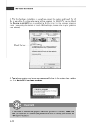
...-GPU settings, please refer to your system and a pop-up message will show in the system tray confirming that you reset the SLI switch card (SLI mode to enable the SLI function for Multi-GPU control. MS-7350 Mainboard 5. Restart your graphics card manual) . Check the box 6. Check the Enable multi-GPU box to non...
...-GPU settings, please refer to your system and a pop-up message will show in the system tray confirming that you reset the SLI switch card (SLI mode to enable the SLI function for Multi-GPU control. MS-7350 Mainboard 5. Restart your graphics card manual) . Check the box 6. Check the Enable multi-GPU box to non...

User Guide
Page 43
... standard customers. You may be slightly different from the latest BIOS and should be held for better system performance. Important 1. MS-7350 Mainboard Entering Setup Power on the screen, press key to enter Setup. It is the BIOS version. Press DEL to enter SETUP If the message ...
... standard customers. You may be slightly different from the latest BIOS and should be held for better system performance. Important 1. MS-7350 Mainboard Entering Setup Power on the screen, press key to enter Setup. It is the BIOS version. Press DEL to enter SETUP If the message ...

User Guide
Page 45
... PC health status. Integrated Peripherals Use this menu to specify your settings for stable system performance. 3-4 H/W Monitor This entry shows your system supports PnP/PCI. MS-7350 Mainboard The Main Menu Standard CMOS Features Use this menu for integrated peripherals.
... PC health status. Integrated Peripherals Use this menu to specify your settings for stable system performance. 3-4 H/W Monitor This entry shows your system supports PnP/PCI. MS-7350 Mainboard The Main Menu Standard CMOS Features Use this menu for integrated peripherals.

User Guide
Page 47
... The month from Sun to set the system to 31 can be keyed by users. year The year can be adjusted by numeric function keys. MS-7350 Mainboard Standard CMOS Features The items in Standard CMOS Features Menu includes some basic setup items. Use the arrow keys to highlight the item and...
... The month from Sun to set the system to 31 can be keyed by users. year The year can be adjusted by numeric function keys. MS-7350 Mainboard Standard CMOS Features The items in Standard CMOS Features Menu includes some basic setup items. Use the arrow keys to highlight the item and...

User Guide
Page 49
This sub-menu shows the CPU information, BIOS version and memory status of your system (read only). 3-8 MS-7350 Mainboard System Information Press to enter the sub-menu, and the following screen appears.
This sub-menu shows the CPU information, BIOS version and memory status of your system (read only). 3-8 MS-7350 Mainboard System Information Press to enter the sub-menu, and the following screen appears.


