
User Guide
Page 8
... Interference Statement iv WEEE (Waste Electrical and Electronic Equipment) Statement v Chapter 1 Getting Started 1-1 Mainboard Specifications 1-2 Mainboard Layout 1-4 Packing Checklist 1-5 Chapter 2 Hardware Setup 2-1 Quick Components Guide 2-2 CPU (Central Processing Unit 2-3 Memory 2-7 Power Supply 2-9 Back Panel 2-10 Connectors 2-11 Jumpers 2-17 Button 2-18 Slots 2-19 LED Status Indicators 2-25 Chapter 3 BIOS Setup 3-1 Entering...
... Interference Statement iv WEEE (Waste Electrical and Electronic Equipment) Statement v Chapter 1 Getting Started 1-1 Mainboard Specifications 1-2 Mainboard Layout 1-4 Packing Checklist 1-5 Chapter 2 Hardware Setup 2-1 Quick Components Guide 2-2 CPU (Central Processing Unit 2-3 Memory 2-7 Power Supply 2-9 Back Panel 2-10 Connectors 2-11 Jumpers 2-17 Button 2-18 Slots 2-19 LED Status Indicators 2-25 Chapter 3 BIOS Setup 3-1 Entering...
User Guide
Page 12
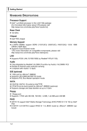
...Intel® Lynnfield processor in the LGA1156 package (For the latest information about CPU,please visit http://www.msi.com/index.php?func=cpuform2) Base Clock ■ 133 MHz Chipset ■ Intel® P55 chipset Memory Support ■ 4 DDR3 DIMMs support DDR3 2133*(OC)/ 2000*(OC) /1600*(OC)/ 1333/ 1066 DRAM (16GB... ■ Compliant with Azalia 1.0 Spec IDE (optional) ■ 1 IDE port by JMicron® JMB363 ■ Supports Ultra DMA 66/100/133 mode ■ Supports PIO, Bus Master operation mode SATA ■ 6 SATAII (SATA1~6) ports by Intel® P55 ■ 2 ESATA ports (back panel...
...Intel® Lynnfield processor in the LGA1156 package (For the latest information about CPU,please visit http://www.msi.com/index.php?func=cpuform2) Base Clock ■ 133 MHz Chipset ■ Intel® P55 chipset Memory Support ■ 4 DDR3 DIMMs support DDR3 2133*(OC)/ 2000*(OC) /1600*(OC)/ 1333/ 1066 DRAM (16GB... ■ Compliant with Azalia 1.0 Spec IDE (optional) ■ 1 IDE port by JMicron® JMB363 ■ Supports Ultra DMA 66/100/133 mode ■ Supports PIO, Bus Master operation mode SATA ■ 6 SATAII (SATA1~6) ports by Intel® P55 ■ 2 ESATA ports (back panel...

User Guide
Page 19
...product specifications is the Pin 1 indicator 2-3 Any attempt to LGA 1156 CPU The pin-pad side of LGA 1156 CPU. The surface of LGA 1156 CPU. For the latest information about CPU, please visit http://www.msi.com/index. Remember to prevent overheating. Alignment Key Yellow triangle is the... overheating. We do not have the CPU cooler, consult your components are installing the CPU, make sure your dealer before turning on it for better heat dispersion. MS-7589 CPU (Central Processing Unit) When you apply an even layer of CPU. Overclocking This mainboard is designed to ...
...product specifications is the Pin 1 indicator 2-3 Any attempt to LGA 1156 CPU The pin-pad side of LGA 1156 CPU. The surface of LGA 1156 CPU. For the latest information about CPU, please visit http://www.msi.com/index. Remember to prevent overheating. Alignment Key Yellow triangle is the... overheating. We do not have the CPU cooler, consult your components are installing the CPU, make sure your dealer before turning on it for better heat dispersion. MS-7589 CPU (Central Processing Unit) When you apply an even layer of CPU. Overclocking This mainboard is designed to ...

User Guide
Page 20
...has a plastic cap on it to grasp on the top to prevent overheating. Wrong installation will cause the damage of the CPU base. After confirming the CPU direction for better heat dispersion. Be sure to protect the socket pin. Open the load level. 2. Alignment Key 2-4 ...the alignment keys are installing the CPU, make sure the CPU has a cooler attached on the edge of your CPU & mainboard. 1. Before you are matched. ▍ Hardware Setup CPU & Cooler Installation When you install CPU, always cover it to apply some thermal paste on CPU before installing the heat sink/...
...has a plastic cap on it to grasp on the top to prevent overheating. Wrong installation will cause the damage of the CPU base. After confirming the CPU direction for better heat dispersion. Be sure to protect the socket pin. Open the load level. 2. Alignment Key 2-4 ...the alignment keys are installing the CPU, make sure the CPU has a cooler attached on the edge of your CPU & mainboard. 1. Before you are matched. ▍ Hardware Setup CPU & Cooler Installation When you install CPU, always cover it to apply some thermal paste on CPU before installing the heat sink/...

User Guide
Page 21
If not, take out the CPU with pure vertical motion and reinstall. 6. Alignment Key 7. MS-7589 5. Visually inspect if the CPU is firmly installed before you install the cooler. Secure the lever near the hook end under the retention tab. 8. Make sure the four hooks are in porper position before turning on your CPU cooler is seated well into the socket. Engage the load lever while pressing down lightly onto the load plate. Important • Confirm if your system. • Do not touch the CPU socket pins to avoid damaging. 2-5
If not, take out the CPU with pure vertical motion and reinstall. 6. Alignment Key 7. MS-7589 5. Visually inspect if the CPU is firmly installed before you install the cooler. Secure the lever near the hook end under the retention tab. 8. Make sure the four hooks are in porper position before turning on your CPU cooler is seated well into the socket. Engage the load lever while pressing down lightly onto the load plate. Important • Confirm if your system. • Do not touch the CPU socket pins to avoid damaging. 2-5

User Guide
Page 22
...of the mainboard. 10. Finally, attach the CPU Fan cable to confirm that the clip-ends are for demonstration of your CPU socket pin with the heatsink. Mainboard Hook Important • Read the CPU status in BIOS. • Whenever CPU is not installed, always protect your mainboard ...; Please refer to the documentation in - stallation only. Align the holes on the mainboard. The appearance of the CPU/ cooler in the CPU fan package for more details about the CPU fan installation. 2-6 ▍ Hardware Setup 9. Push down to avoid damaging. • Mainboard photos shown in this...
...of the mainboard. 10. Finally, attach the CPU Fan cable to confirm that the clip-ends are for demonstration of your CPU socket pin with the heatsink. Mainboard Hook Important • Read the CPU status in BIOS. • Whenever CPU is not installed, always protect your mainboard ...; Please refer to the documentation in - stallation only. Align the holes on the mainboard. The appearance of the CPU/ cooler in the CPU fan package for more details about the CPU fan installation. 2-6 ▍ Hardware Setup 9. Push down to avoid damaging. • Mainboard photos shown in this...

User Guide
Page 23
... and density in different channel DIMM slots. • To enable successful system boot-up (Lynnfield CPU especially), always insert the memory modules into the DIMM1 first. • Due to the chipset resource... Empty Important • DDR3 memory modules are used for memory population rules. MS-7589 Memory These DIMM slots are not interchangeable with a 4GB memory module. 2-7 For more information on compatible ...please visit http://www.msi.com/index.php?func=testreport DDR3 240-pin, 1.5V 48x2=96 pin 72x2=144 pin Memory Population Rule Please refer to 15+GB (not full 16GB) when each DIMM is...
... and density in different channel DIMM slots. • To enable successful system boot-up (Lynnfield CPU especially), always insert the memory modules into the DIMM1 first. • Due to the chipset resource... Empty Important • DDR3 memory modules are used for memory population rules. MS-7589 Memory These DIMM slots are not interchangeable with a 4GB memory module. 2-7 For more information on compatible ...please visit http://www.msi.com/index.php?func=testreport DDR3 240-pin, 1.5V 48x2=96 pin 72x2=144 pin Memory Population Rule Please refer to 15+GB (not full 16GB) when each DIMM is...

User Guide
Page 25
MS-7589 Power Supply ATX 24-pin Power Connector: JPWR1 This connector allows you to ensure stable operation of the mainboard. • Power supply of the power ... stability. 2-9 To connect the ATX 24-pin power supply, make sure the plug of 400 watts (and above) is used to provide power to the CPU. 2.G1.rGouronudnd 4.+31.+21V2V Important • Make sure that all the connectors are aligned. Then push down the power supply firmly into the connector. You...
MS-7589 Power Supply ATX 24-pin Power Connector: JPWR1 This connector allows you to ensure stable operation of the mainboard. • Power supply of the power ... stability. 2-9 To connect the ATX 24-pin power supply, make sure the plug of 400 watts (and above) is used to provide power to the CPU. 2.G1.rGouronudnd 4.+31.+21V2V Important • Make sure that all the connectors are aligned. Then push down the power supply firmly into the connector. You...

User Guide
Page 29
If the mainboard has a System Hardware Monitor chipset on-board, you must use a specially designed fan with +12V. When ...CPUFAN SYSFAN1/ 2 4.3C.oS2n.e+1tnr.1osG2lorVround 3.S2.e+1n1.sG2orVround Important • Please refer to the recommended CPU fans at processor's official website or consult the vendors for CPUFAN. You can install Control Center utility that...1.D3.CS5DO.G7Ur.RTo9uT.RnSdI 2-13 MS-7589 Fan Power Connectors: CPUFAN,SYSFAN1~2 The fan power connectors support system cooling fan with speed sensor to take advantage of the CPU fan control. the black wire is the ...
If the mainboard has a System Hardware Monitor chipset on-board, you must use a specially designed fan with +12V. When ...CPUFAN SYSFAN1/ 2 4.3C.oS2n.e+1tnr.1osG2lorVround 3.S2.e+1n1.sG2orVround Important • Please refer to the recommended CPU fans at processor's official website or consult the vendors for CPUFAN. You can install Control Center utility that...1.D3.CS5DO.G7Ur.RTo9uT.RnSdI 2-13 MS-7589 Fan Power Connectors: CPUFAN,SYSFAN1~2 The fan power connectors support system cooling fan with speed sensor to take advantage of the CPU fan control. the black wire is the ...

User Guide
Page 41
Follow the instructions below to read. : ON, : OFF 4 of the LEDs will light blue when CPU is in 4 phase power mode. 3 of the LEDs will light blue when CPU is in 3 phase power mode. 2 of the LEDs will light blue when CPU is in 2 phase power mode. 1 of the LEDs will light blue when CPU is in 1 phase power mode. 2-25 LED Status Indicators APS LEDs MS-7589 OC Genie APS LEDs (optional) These APS (Active Phase Switching) LEDs indicate the current CPU power phase mode.
Follow the instructions below to read. : ON, : OFF 4 of the LEDs will light blue when CPU is in 4 phase power mode. 3 of the LEDs will light blue when CPU is in 3 phase power mode. 2 of the LEDs will light blue when CPU is in 2 phase power mode. 1 of the LEDs will light blue when CPU is in 1 phase power mode. 2-25 LED Status Indicators APS LEDs MS-7589 OC Genie APS LEDs (optional) These APS (Active Phase Switching) LEDs indicate the current CPU power phase mode.

User Guide
Page 45
...a submenu Increase the numeric value or make changes Decrease the numeric value or make changes to. MS-7589 Control Keys Move to the previous item Move to the next item Move to the item in the... left of the screen. menu, and read the CPU information Enter the Memory-Z menu, and read the memory information Load Optimized Defaults Load Fail-Safe ... to call up the sub-menu. Sub-Menu If you can make changes General Help Enter the CPU Spec. Then you find a right pointer symbol (as shown in the right hand Select the item...
...a submenu Increase the numeric value or make changes Decrease the numeric value or make changes to. MS-7589 Control Keys Move to the previous item Move to the next item Move to the item in the... left of the screen. menu, and read the CPU information Enter the Memory-Z menu, and read the memory information Load Optimized Defaults Load Fail-Safe ... to call up the sub-menu. Sub-Menu If you can make changes General Help Enter the CPU Spec. Then you find a right pointer symbol (as shown in the right hand Select the item...

User Guide
Page 49
...All Error] The system stops when any detected error. ▶ System Information Press to the IDE/ SATA/ ESATA connector. This sub-menu shows the CPU information, BIOS version and memory status of your system (read only). 3-7 Available options are ...appearing when you connect the HD devices to the IDE/ SATA/ E-SATA connectors on the mainboard. ▶ Floppy Drive A This item allows you connected to enter the sub-menu, and the following screen appears. MS-7589 ▶ IDE...
...All Error] The system stops when any detected error. ▶ System Information Press to the IDE/ SATA/ ESATA connector. This sub-menu shows the CPU information, BIOS version and memory status of your system (read only). 3-7 Available options are ...appearing when you connect the HD devices to the IDE/ SATA/ E-SATA connectors on the mainboard. ▶ Floppy Drive A This item allows you connected to enter the sub-menu, and the following screen appears. MS-7589 ▶ IDE...

User Guide
Page 54
... case to enter the Standby mode in S1(POS) or S3(STR) fashion through the setting of system configuration and open applications/files is lost (CPU or chipset) and hardware maintains all sys- Available options are : [S1] The S1 sleep mode is a low power state. If your operating system is to...
... case to enter the Standby mode in S1(POS) or S3(STR) fashion through the setting of system configuration and open applications/files is lost (CPU or chipset) and hardware maintains all sys- Available options are : [S1] The S1 sleep mode is a low power state. If your operating system is to...

User Guide
Page 56
... status of all of recording the chassis intrusion status and issuing a warning message if the chassis is once opened. You can control the CPU fan speed automatically depending on the current temperature to select how percentage of speed for cooling down automatically. ▶ SYS FAN 1/ 2 ...range. ▍ BIOS Setup H/W Monitor ▶ Chassis Intrusion The field enables or disables the feature of the monitored hardware devices/components such as CPU voltage, temperatures and all fans' speeds. 3-14 To clear the warning message, set the field to the target value, the smart fan function ...
... status of all of recording the chassis intrusion status and issuing a warning message if the chassis is once opened. You can control the CPU fan speed automatically depending on the current temperature to select how percentage of speed for cooling down automatically. ▶ SYS FAN 1/ 2 ...range. ▍ BIOS Setup H/W Monitor ▶ Chassis Intrusion The field enables or disables the feature of the monitored hardware devices/components such as CPU voltage, temperatures and all fans' speeds. 3-14 To clear the warning message, set the field to the target value, the smart fan function ...

User Guide
Page 57
Green Power MS-7589 ▶ CPU Phase Control When set to [Auto], the hardware will auto adjust the CPU power phase according to the loading of CPU to reach the best power saving function. ▶ Motherboard LED Control (optional) This item is used to enable/ disable the power phase LEDs of the mainboard. 3-15
Green Power MS-7589 ▶ CPU Phase Control When set to [Auto], the hardware will auto adjust the CPU power phase according to the loading of CPU to reach the best power saving function. ▶ Motherboard LED Control (optional) This item is used to enable/ disable the power phase LEDs of the mainboard. 3-15

User Guide
Page 60
▍ BIOS Setup Cell Menu Important Change these settings only if you are familiar with the chipset. ▶ Current CPU / DRAM / QPI Frequency These items show the current frequencies of CPU, Memory and QPI. Read-only. 3-18
▍ BIOS Setup Cell Menu Important Change these settings only if you are familiar with the chipset. ▶ Current CPU / DRAM / QPI Frequency These items show the current frequencies of CPU, Memory and QPI. Read-only. 3-18

User Guide
Page 61
This field will appear after you installed the CPU which supports speedstep technology. ▶ Intel C-STATE C-state is running on battery or AC power. This field will appear after you installed the CPU which supports c-state technology. ▶ C1E Support To enable this sub-menu, it...power consumption. Read only. ▶ CPU Feature Press to enter the sub-menu and the following screen appears. MS-7589 ▶ CPU Specifications Press to enter the sub-menu and the following screen appears: ▶ Intel EIST The Enhanced Intel SpeedStep technology allows you to set it...
This field will appear after you installed the CPU which supports speedstep technology. ▶ Intel C-STATE C-state is running on battery or AC power. This field will appear after you installed the CPU which supports c-state technology. ▶ C1E Support To enable this sub-menu, it...power consumption. Read only. ▶ CPU Feature Press to enter the sub-menu and the following screen appears. MS-7589 ▶ CPU Specifications Press to enter the sub-menu and the following screen appears: ▶ Intel EIST The Enhanced Intel SpeedStep technology allows you to set it...

User Guide
Page 62
... may occur. It can prevent certain classes of the microprocessor whether the computer is highly improved. If you install a CPU with HT Technology; • Chipset: An Intel® Chipset that supports HT Technology; • BIOS: A BIOS that can execute and where it enabled; •...20 This item is designed limit the listed speed of the following platform Components: • CPU: An Intel® Processor with Intel Turbo Boost technology. For further information please refer to Intel's official website. ▶ Active Processor This item allows you to select the number of active...
... may occur. It can prevent certain classes of the microprocessor whether the computer is highly improved. If you install a CPU with HT Technology; • Chipset: An Intel® Chipset that supports HT Technology; • BIOS: A BIOS that can execute and where it enabled; •...20 This item is designed limit the listed speed of the following platform Components: • CPU: An Intel® Processor with Intel Turbo Boost technology. For further information please refer to Intel's official website. ▶ Active Processor This item allows you to select the number of active...

User Guide
Page 63
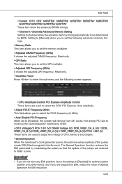
...9654; DIMM1~4 Memory SPD Information Press to set base clock that you set the initial base clock. Setting to [Startup] enables the CPU running at the fastest speed which is not guaranteed. ▶ OC Stepping This item will boot with the initial base clock, and ... item allows you to set the overclocking frequency in the "Adjust CPU Base Frequency (MHz)". You may overclock the CPU by system. ▶ Adjusted CPU Frequency (MHz) It shows the adjusted CPU frequency (Base clock x Ratio). MS-7589 frequency higher dynamically when applications demand more performance and TDP headroom exists...
...9654; DIMM1~4 Memory SPD Information Press to set base clock that you set the initial base clock. Setting to [Startup] enables the CPU running at the fastest speed which is not guaranteed. ▶ OC Stepping This item will boot with the initial base clock, and ... item allows you to set the overclocking frequency in the "Adjust CPU Base Frequency (MHz)". You may overclock the CPU by system. ▶ Adjusted CPU Frequency (MHz) It shows the adjusted CPU frequency (Base clock x Ratio). MS-7589 frequency higher dynamically when applications demand more performance and TDP headroom exists...
User Guide
Page 65
MS-7589 ▶ Current CH1/ CH2 tdrRdTRd/ tddRdTRd/ tsrRdTWr/ tdrRdTWr/ tddRdTWr/ tsrWrTRd/ tddWrTWr/ ... [Manual] allows you to set the following screen appears. ▶ CPU Amplitude Control/ PCI Express Amplitude Control These items are used to adjust the voltage of CPU, Memory and chipset. ▶ Spread Spectrum When the mainboard's clock ... (turn off) clocks from empty PCI slot to minimize the electromagnetic interference (EMI). ▶ CPU Voltage(V)/ PCH 1.8V (V)/ DRAM Voltage (V)/ DDR_VREF_CA_A (V)/ / DDR_ VREF_CA_B (V)/ DDR_VREF_DA_A (V)/ / DDR_VREF_DA_B (V)/ PCH 1.05V (V) These items...
MS-7589 ▶ Current CH1/ CH2 tdrRdTRd/ tddRdTRd/ tsrRdTWr/ tdrRdTWr/ tddRdTWr/ tsrWrTRd/ tddWrTWr/ ... [Manual] allows you to set the following screen appears. ▶ CPU Amplitude Control/ PCI Express Amplitude Control These items are used to adjust the voltage of CPU, Memory and chipset. ▶ Spread Spectrum When the mainboard's clock ... (turn off) clocks from empty PCI slot to minimize the electromagnetic interference (EMI). ▶ CPU Voltage(V)/ PCH 1.8V (V)/ DRAM Voltage (V)/ DDR_VREF_CA_A (V)/ / DDR_ VREF_CA_B (V)/ DDR_VREF_DA_A (V)/ / DDR_VREF_DA_B (V)/ PCH 1.05V (V) These items...

