
User Guide
Page 8
...2-2 Memory ...2-7 Power Supply ...2-8 Back Panel ...2-11 Connectors ...2-12 Jumper ...2-19 Button ...2-20 Slots ...2-21 LED Status Indicators 2-23 Chapter 3 BIOS Setup 3-1 Entering Setup ...3-2 The Main Menu ...3-4 Standard CMOS Features 3-6 Advanced BIOS Features 3-9 Integrated Peripherals 3-12 Power Management Setup 3-14 PNP/PCI Configurations 3-17 H/W Monitor ...3-19 Cell Menu ...3-20 Load Fail-Safe/ Optimized Defaults 3-26 BIOS Setting Password 3-27 Appendix A Realtek ALC888/888T Audio A-1 Installation for W indows 2000/XP A-2 Installing the Realtek HD Audio Driver A-2 Software...
...2-2 Memory ...2-7 Power Supply ...2-8 Back Panel ...2-11 Connectors ...2-12 Jumper ...2-19 Button ...2-20 Slots ...2-21 LED Status Indicators 2-23 Chapter 3 BIOS Setup 3-1 Entering Setup ...3-2 The Main Menu ...3-4 Standard CMOS Features 3-6 Advanced BIOS Features 3-9 Integrated Peripherals 3-12 Power Management Setup 3-14 PNP/PCI Configurations 3-17 H/W Monitor ...3-19 Cell Menu ...3-20 Load Fail-Safe/ Optimized Defaults 3-26 BIOS Setting Password 3-27 Appendix A Realtek ALC888/888T Audio A-1 Installation for W indows 2000/XP A-2 Installing the Realtek HD Audio Driver A-2 Software...
User Guide
Page 11
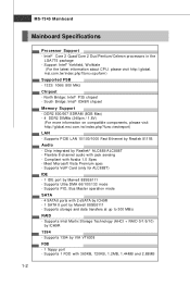
... compatible components, please visit ht t p: / / global. t w / index. Flexible 8-channel audio with 360KB, 720KB, 1.2MB, 1.44MB and 2.88MB 1-2 Meet Microsoft Vista Premium spec - North Bridge: Intel® P35 chipset - p hp?func =t est report ) LAN - South Bridge: Intel® ICH9R chipset Memory Support - Chip integrated by Realtek 8111B Audio - m si. t w / index. c om . Supports PCIE LAN 10/100/1000 Fast Ethernet by Realtek® ALC888/ALC888T - Supports Intel Martix Storage Technology (AHCI + RAID...
... compatible components, please visit ht t p: / / global. t w / index. Flexible 8-channel audio with 360KB, 720KB, 1.2MB, 1.44MB and 2.88MB 1-2 Meet Microsoft Vista Premium spec - North Bridge: Intel® P35 chipset - p hp?func =t est report ) LAN - South Bridge: Intel® ICH9R chipset Memory Support - Chip integrated by Realtek 8111B Audio - m si. t w / index. c om . Supports PCIE LAN 10/100/1000 Fast Ethernet by Realtek® ALC888/ALC888T - Supports Intel Martix Storage Technology (AHCI + RAID...
User Guide
Page 12
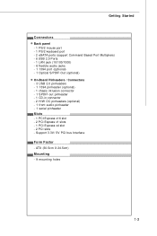
... Started Connectors Back panel - 1 PS/2 mouse port - 1 PS/2 keyboard port - 2 eSATA ports (support Command Based Port Multipliers) - 6 USB 2.0 Ports - 1 LAN jack (10/100/1000) - 6 flexible audio jacks - 1 1394 port (optional) - 1 Optical S/PDIF-Out (optional) On-Board Pinheaders / Connectors - 3 USB 2.0 pinheaders - 1 1394 pinheader (optional) - 1 chasis intrusion connector - 1 SPDIF-out pinheader - 1 CD-in connector - 2 H/W OC pinheaders (optional) - 1 front audio pinheader - 1 serial pinheader Slots - 1 PCI Express x16 slot - 2 PCI Express x1 slots - 1 PCI Express x4 slot - 2 PCI slots - ATX...
... Started Connectors Back panel - 1 PS/2 mouse port - 1 PS/2 keyboard port - 2 eSATA ports (support Command Based Port Multipliers) - 6 USB 2.0 Ports - 1 LAN jack (10/100/1000) - 6 flexible audio jacks - 1 1394 port (optional) - 1 Optical S/PDIF-Out (optional) On-Board Pinheaders / Connectors - 3 USB 2.0 pinheaders - 1 1394 pinheader (optional) - 1 chasis intrusion connector - 1 SPDIF-out pinheader - 1 CD-in connector - 2 H/W OC pinheaders (optional) - 1 front audio pinheader - 1 serial pinheader Slots - 1 PCI Express x16 slot - 2 PCI Express x1 slots - 1 PCI Express x4 slot - 2 PCI slots - ATX...
User Guide
Page 26
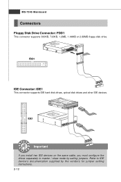
IDE1 Important If you install two IDE devices on the same cable, you must configure the drives separately to IDE device's documentation supplied by setting jumpers. FDD1 IDE Connector: IDE1 This connector supports IDE hard disk drives, optical disk drives and other IDE devices. MS-7345 Mainboard Connectors Floppy Disk Drive Connector: FDD1 This connector supports 360KB, 720KB, 1.2MB, 1.44MB or 2.88MB floppy disk drive. Refer to master / slave mode by the vendors for jumper setting instructions. 2-12
IDE1 Important If you install two IDE devices on the same cable, you must configure the drives separately to IDE device's documentation supplied by setting jumpers. FDD1 IDE Connector: IDE1 This connector supports IDE hard disk drives, optical disk drives and other IDE devices. MS-7345 Mainboard Connectors Floppy Disk Drive Connector: FDD1 This connector supports 360KB, 720KB, 1.2MB, 1.44MB or 2.88MB floppy disk drive. Refer to master / slave mode by the vendors for jumper setting instructions. 2-12
User Guide
Page 28
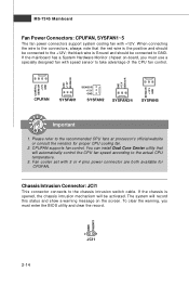
... and show a warning message on -board, you must use a specially designed fan with speed sensor to the chassis intrusion switch cable. CPUFAN supports fan control. To clear the warning, you must enter the BIOS utility and clear the record. Please refer to the actual CPU temperature. 3. W hen connecting the wire to the connectors, always note that will automatically control the CPU fan speed according to the recommended CPU fans at processor's official website or consult the vendors...
... and show a warning message on -board, you must use a specially designed fan with speed sensor to the chassis intrusion switch cable. CPUFAN supports fan control. To clear the warning, you must enter the BIOS utility and clear the record. Please refer to the actual CPU temperature. 3. W hen connecting the wire to the connectors, always note that will automatically control the CPU fan speed according to the recommended CPU fans at processor's official website or consult the vendors...
User Guide
Page 33
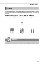
This section will explain how to increase the processor frequency by changing the jumpers JB1 and JB2. Hardware Setup Jumper The motherboard provides the following jumper for you power off the system before changing the jumpers 2-19 Follow the instructions below to set the FSB. 1 JB1 JB2 1 3 200 MHz 1 3 266 MHz 1 3 333 MHz Important Make sure that you to set the computer's function. Hardware Overclock FSB Jumpers: JB1, JB2 (optional) You can overclock the FSB to change your motherboard's function through the use of jumper.
This section will explain how to increase the processor frequency by changing the jumpers JB1 and JB2. Hardware Setup Jumper The motherboard provides the following jumper for you power off the system before changing the jumpers 2-19 Follow the instructions below to set the FSB. 1 JB1 JB2 1 3 200 MHz 1 3 266 MHz 1 3 333 MHz Important Make sure that you to set the computer's function. Hardware Overclock FSB Jumpers: JB1, JB2 (optional) You can overclock the FSB to change your motherboard's function through the use of jumper.
User Guide
Page 34
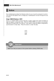
... to clear the system configuration, use of button. Clear CMOS Button: SW1 There is turned on board that you power off the system before clearing CMOS data. 2-20 Press the button to set the computer's function. SW1 Important Make sure that has a power supply from external battery to clear data. This section will explain how to change your motherboard's function through the use the button to keep the system configuration data. With the CMOS RAM...
... to clear the system configuration, use of button. Clear CMOS Button: SW1 There is turned on board that you power off the system before clearing CMOS data. 2-20 Press the button to set the computer's function. SW1 Important Make sure that has a power supply from external battery to clear data. This section will explain how to change your motherboard's function through the use the button to keep the system configuration data. With the CMOS RAM...
User Guide
Page 36
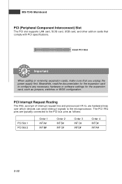
MS-7345 Mainboard PCI (Peripheral Component Interconnect) Slot The PCI slot supports LAN card, SCSI card, USB card, and other add-on cards that comply with PCI specifications. 32-bit PCI Slot Important When adding or removing expansion cards, make sure that you unplug the power supply first. Meanwhile, read the documentation for the expansion card to configure any necessary hardware or software settings for the expansion card, such as follows: PCI Slot 1 PCI Slot 2 Order 1 INT A# INT B# Order 2 INT B# INT...
MS-7345 Mainboard PCI (Peripheral Component Interconnect) Slot The PCI slot supports LAN card, SCSI card, USB card, and other add-on cards that comply with PCI specifications. 32-bit PCI Slot Important When adding or removing expansion cards, make sure that you unplug the power supply first. Meanwhile, read the documentation for the expansion card to configure any necessary hardware or software settings for the expansion card, such as follows: PCI Slot 1 PCI Slot 2 Order 1 INT A# INT B# Order 2 INT B# INT...
User Guide
Page 45
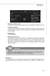
... connected to set the type of floppy drives installed. Setting to the IDE/ SATA connector on the mainboard. Available options: [None], [360K, 5.25 in.], [1.2M, 5.25 in.], [720K, 3.5 in.], [1.44M, 3.5 in.], [2.88M, 3.5 in.]. 3-7 Important Serial-ATA 1/2/3/4/5/6 Channel are appearing when you to predict hard disk failure. LBA/Large M ode This allows you connect the HD devices to Auto enables LBA mode if the device supports it and the devices is a utility that monitors your disk status to enable or disable...
... connected to set the type of floppy drives installed. Setting to the IDE/ SATA connector on the mainboard. Available options: [None], [360K, 5.25 in.], [1.2M, 5.25 in.], [720K, 3.5 in.], [1.44M, 3.5 in.], [2.88M, 3.5 in.]. 3-7 Important Serial-ATA 1/2/3/4/5/6 Channel are appearing when you to predict hard disk failure. LBA/Large M ode This allows you connect the HD devices to Auto enables LBA mode if the device supports it and the devices is a utility that monitors your disk status to enable or disable...
User Guide
Page 47
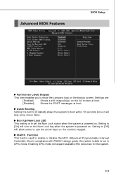
.... Enabling APIC mode will allow users to boot within 10 seconds since it will turn on the Num Lock key when the system is powered on the bootup screen. Setting to [On] will skip some check items. Boot Up Num-Lock LED This setting is to enable or disable the APIC (Advanced Programmable Interrupt Controller). Due to compliance with PC2001 design guide, the system is used to set...
.... Enabling APIC mode will allow users to boot within 10 seconds since it will turn on the Num Lock key when the system is powered on the bootup screen. Setting to [On] will skip some check items. Boot Up Num-Lock LED This setting is to enable or disable the APIC (Advanced Programmable Interrupt Controller). Due to compliance with PC2001 design guide, the system is used to set...
User Guide
Page 50
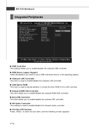
... Mainboard Integrated Peripherals USB Controller This setting allows you to use a USB-interfaced device in the operating system. USB Device Legacy Support Select [Enabled] if you need to enable/disable the onboard USB controller. Extra IDE Controller This item allows you to enable/disable the onboard audio controller. On-Chip ATA Devices Press to enable/disable the onboard IDE controller. Onboard IEEE1394 Controller This item allows you to enter the sub-menu and the following screen appears: 3-12 LAN Option ROM This item is used to invoke the Boot ROM of the LAN controller...
... Mainboard Integrated Peripherals USB Controller This setting allows you to use a USB-interfaced device in the operating system. USB Device Legacy Support Select [Enabled] if you need to enable/disable the onboard USB controller. Extra IDE Controller This item allows you to enable/disable the onboard audio controller. On-Chip ATA Devices Press to enable/disable the onboard IDE controller. Onboard IEEE1394 Controller This item allows you to enter the sub-menu and the following screen appears: 3-12 LAN Option ROM This item is used to invoke the Boot ROM of the LAN controller...
User Guide
Page 51
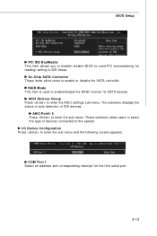
RAID Mode This item is used PCI busmastering for reading/ writing to IDE drives. These submenu allow users to enable or disable the SATA controller. The submenu displays the status of auto detection of devices connected to the system. Oc-Chip SATA Controller These items allow users to select the type of IDE devices. I/O Device Configuration Press to enter the sub-menu. AHCI Port0~5 Press to enter the sub-menu and the following screen appears: COM Port 1 Select an address and corresponding...
RAID Mode This item is used PCI busmastering for reading/ writing to IDE drives. These submenu allow users to enable or disable the SATA controller. The submenu displays the status of auto detection of devices connected to the system. Oc-Chip SATA Controller These items allow users to select the type of IDE devices. I/O Device Configuration Press to enter the sub-menu. AHCI Port0~5 Press to enter the sub-menu and the following screen appears: COM Port 1 Select an address and corresponding...
User Guide
Page 55
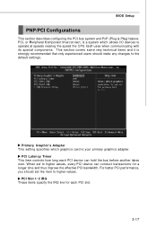
... any changes to operate at speeds nearing the speed the CPU itself uses when communicating with its special components. This section covers some very technical items and it is your primary graphics adapter. PCI, or Peripheral Component Interconnect, is a system which graphics card is strongly recommended that only experienced users should set to higher values. BIOS Setup PNP/PCI Configurations This section describes configuring the PCI bus system...
... any changes to operate at speeds nearing the speed the CPU itself uses when communicating with its special components. This section covers some very technical items and it is your primary graphics adapter. PCI, or Peripheral Component Interconnect, is a system which graphics card is strongly recommended that only experienced users should set to higher values. BIOS Setup PNP/PCI Configurations This section describes configuring the PCI bus system...
User Guide
Page 57
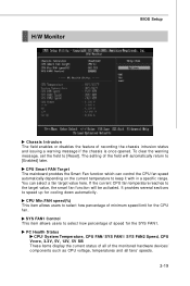
... to keep it with in a specific range. The setting of the field will be activated. SYS FAN1 Control This item allows users to [Enabled] later. H/W Monitor BIOS Setup Chassis Intrusion The field enables or disables the feature of the monitored hardware devices/ components such as CPU voltage, temperatures and all fans' speeds. 3-19 If the current CPU fan temperature reaches to the target value, the smart fan function will automatically return to select...
... to keep it with in a specific range. The setting of the field will be activated. SYS FAN1 Control This item allows users to [Enabled] later. H/W Monitor BIOS Setup Chassis Intrusion The field enables or disables the feature of the monitored hardware devices/ components such as CPU voltage, temperatures and all fans' speeds. 3-19 If the current CPU fan temperature reaches to the target value, the smart fan function will automatically return to select...
User Guide
Page 59
.../2/3 setting Due to be powered only when users' PC need to run smoothly and faster. Adjusted CPU Frequency It shows the adjusted CPU frequency (FSB x Ratio). Adjust CPU FSB Frequency This item allows you find the PC appears to D.O.T can detect the PCIE loading and increase the frequency with 3 overclocking steps. Usually the Dynamic Overclocking Technology will restore the default settings instead. If you to Disable. BIOS Setup running on battery...
.../2/3 setting Due to be powered only when users' PC need to run smoothly and faster. Adjusted CPU Frequency It shows the adjusted CPU frequency (FSB x Ratio). Adjust CPU FSB Frequency This item allows you find the PC appears to D.O.T can detect the PCIE loading and increase the frequency with 3 overclocking steps. Usually the Dynamic Overclocking Technology will restore the default settings instead. If you to Disable. BIOS Setup running on battery...
User Guide
Page 61
... It allows I /O Power / SB Core Power These items dispaly the power status of CPU, Memory, FSB and chipset. Spread Spectrum W hen the motherboard's clock generator pulses, the extreme values (spikes) of the pulses create EMI (Electromagnetic Interference). Auto Disable DIMM/PCI Frequency W hen set to select the PCIE frequency (in clock speed which may just cause your overclocked processor to [Disabled], the field is adjustable. CPU Voltage / Momory Voltage / VTT FSB Voltage / NB Voltage / SB I /O gating...
... It allows I /O Power / SB Core Power These items dispaly the power status of CPU, Memory, FSB and chipset. Spread Spectrum W hen the motherboard's clock generator pulses, the extreme values (spikes) of the pulses create EMI (Electromagnetic Interference). Auto Disable DIMM/PCI Frequency W hen set to select the PCIE frequency (in clock speed which may just cause your overclocked processor to [Disabled], the field is adjustable. CPU Voltage / Momory Voltage / VTT FSB Voltage / NB Voltage / SB I /O gating...
User Guide
Page 67
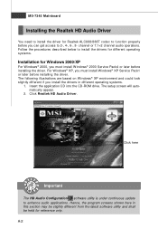
Click Realtek HD Audio Driver. Insert the application CD into the CD-ROM drive. Hence, the program screens shown here in different operating systems. 1. Click here Important The HD Audio Configuration software utility is under continuous update to install the drivers for different operating systems. Installation for reference only. MS-7345 Mainboard Installing the Realtek HD Audio Driver You need to install the driver for Realtek ALC888/888T codec to...
Click Realtek HD Audio Driver. Insert the application CD into the CD-ROM drive. Hence, the program screens shown here in different operating systems. 1. Click here Important The HD Audio Configuration software utility is under continuous update to install the drivers for different operating systems. Installation for reference only. MS-7345 Mainboard Installing the Realtek HD Audio Driver You need to install the driver for Realtek ALC888/888T codec to...
User Guide
Page 90
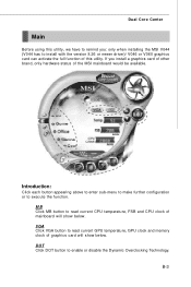
... to enter sub-menu to make further configuration or to enable or disable the Dynamic Overclocking Technology. MB Click MB button to read current GPU temperature, GPU clock and memory clock of graphics card will show below . B-3 Dual Core Center Main Before using this utility, we have to remind you install a graphics card of other brand, only hardware status of the MSI mainboard would be available. VGA Click VGA button to install with the version 8.26 or newer driver)/ V046...
... to enter sub-menu to make further configuration or to enable or disable the Dynamic Overclocking Technology. MB Click MB button to read current GPU temperature, GPU clock and memory clock of graphics card will show below . B-3 Dual Core Center Main Before using this utility, we have to remind you install a graphics card of other brand, only hardware status of the MSI mainboard would be available. VGA Click VGA button to install with the version 8.26 or newer driver)/ V046...
User Guide
Page 101
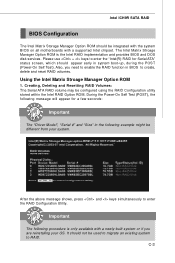
... RAID Configuration Utility. During the Power-On Self Test (POST), the following message will appear for Serial ATA" status screen, which should not be used to migrate an existing system to RAID. C-3 Please use + keys to enter the "Intel(R) RAID for a few seconds: Important The "Driver Model", "Serial #" and "Size" in the following procedure is the Intel RAID implementation and provides BIOS and DOS disk services. The Intel Matrix Stroage Manager Option ROM...
... RAID Configuration Utility. During the Power-On Self Test (POST), the following message will appear for Serial ATA" status screen, which should not be used to migrate an existing system to RAID. C-3 Please use + keys to enter the "Intel(R) RAID for a few seconds: Important The "Driver Model", "Serial #" and "Size" in the following procedure is the Intel RAID implementation and provides BIOS and DOS disk services. The Intel Matrix Stroage Manager Option ROM...
User Guide
Page 107
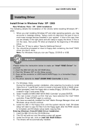
... auto-run and the setup screen will need to copy the files from the floppy again after selecting the location to install Vista click on "Load Driver" button to install a third party SCSI or RAID driver. 5. Press the "S" key to continue. 8. For W indows Vista: During the Operating system installation, after the RAID volume is the case, then you can use Floppy, CD/DVD or USB. W hen prompted, insert the floppy disk or media (Floppy...
... auto-run and the setup screen will need to copy the files from the floppy again after selecting the location to install Vista click on "Load Driver" button to install a third party SCSI or RAID driver. 5. Press the "S" key to continue. 8. For W indows Vista: During the Operating system installation, after the RAID volume is the case, then you can use Floppy, CD/DVD or USB. W hen prompted, insert the floppy disk or media (Floppy...


