User Guide
Page 5
Hardware Setup 2-1 Quick Components Guide 2-2 Central Processing Unit: CPU 2-2 CPU Installation Procedures for Socket 754 2-4 Installing AMD Athlon64 CPU Cooler Set 2-5 Memory ...2-7 Introduction to DDR SDRAM 2-7 DIMM Module Combination 2-7 Installing DDR Modules 2-8 Power Supply ...2-9 ATX 20-Pin Power Connector: JWR1 2-9 ATX 12V Power Connector: ...
Hardware Setup 2-1 Quick Components Guide 2-2 Central Processing Unit: CPU 2-2 CPU Installation Procedures for Socket 754 2-4 Installing AMD Athlon64 CPU Cooler Set 2-5 Memory ...2-7 Introduction to DDR SDRAM 2-7 DIMM Module Combination 2-7 Installing DDR Modules 2-8 Power Supply ...2-9 ATX 20-Pin Power Connector: JWR1 2-9 ATX 12V Power Connector: ...
User Guide
Page 9
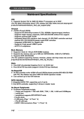
...h Can connect up to four IDE devices SATA Interface h Integrated SATA PHY, supporting up to 3400+. (For the latest information about CPU, please visit http://www.msi.com.tw/program/ products/mainboard/mbd/pro_mbd_cpu_support.php) Chipset h nVIDIA nForce3 250Gb - Supports 8 high speed USB2.0 ports. - Supports ...RAID controller and dual channel ATA 133/100/66/33 master mode EIDE controller. - Integrated nVIDIA MAC for Gigabit LAN. - 7030 ATX Mainboard Mainboard Specifications CPU h Supports Socket-754 for AMD K8 Athlon™ processor up to 3GB (for DDR333/266) / 2GB (For DDR400) .
...h Can connect up to four IDE devices SATA Interface h Integrated SATA PHY, supporting up to 3400+. (For the latest information about CPU, please visit http://www.msi.com.tw/program/ products/mainboard/mbd/pro_mbd_cpu_support.php) Chipset h nVIDIA nForce3 250Gb - Supports 8 high speed USB2.0 ports. - Supports ...RAID controller and dual channel ATA 133/100/66/33 master mode EIDE controller. - Integrated nVIDIA MAC for Gigabit LAN. - 7030 ATX Mainboard Mainboard Specifications CPU h Supports Socket-754 for AMD K8 Athlon™ processor up to 3GB (for DDR333/266) / 2GB (For DDR400) .

User Guide
Page 13
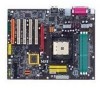
Hardware Setup Chapter 2. Hardware Setup Hardware Setup This chapter tells you how to install the CPU, memory modules, and expansion cards, as well as the mouse, keyboard, etc. Also, it provides the instructions on connecting the peripheral devices, such as how to setup the jumpers on the mainboard. While doing the installation, be careful in holding the components and follow the installation procedures. 2-1
Hardware Setup Chapter 2. Hardware Setup Hardware Setup This chapter tells you how to install the CPU, memory modules, and expansion cards, as well as the mouse, keyboard, etc. Also, it provides the instructions on connecting the peripheral devices, such as how to setup the jumpers on the mainboard. While doing the installation, be careful in holding the components and follow the installation procedures. 2-1
User Guide
Page 15
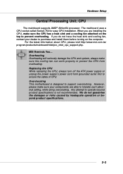
... product specifications is designed to support overclocking. For the latest information about CPU, please visit http://www.msi.com.tw/ program/products/mainboard/mbd/pro_mbd_cpu_support.php. Replacing the CPU While replacing the CPU, always turn off the ATX power supply or unplug the power supply's... make sure the CPU has a heat sink and a cooling fan attached on the computer. If you are installing the CPU, make sure your dealer to purchase and install them before turning on the top to operate beyond product specifications. 2-3 Overclocking This motherboard is not recommended....
... product specifications is designed to support overclocking. For the latest information about CPU, please visit http://www.msi.com.tw/ program/products/mainboard/mbd/pro_mbd_cpu_support.php. Replacing the CPU While replacing the CPU, always turn off the ATX power supply or unplug the power supply's... make sure the CPU has a heat sink and a cooling fan attached on the computer. If you are installing the CPU, make sure your dealer to purchase and install them before turning on the top to operate beyond product specifications. 2-3 Overclocking This motherboard is not recommended....
User Guide
Page 16
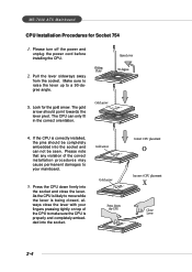
...move while the lever is properly and completely embedded into the socket. 2-4 Make sure to raise the lever up to make sure the CPU is being closed, always close the lever. Please note that any violation of the correct installation procedures may cause permanent damages to your ...fingers pressing tightly on top of the CPU to a 90-degree angle. 3. The gold arrow should be seen. Please turn off the power and unplug the power cord before installing the CPU. 2. Pull the lever sideways away from the socket. MS-7030 ATX Mainboard CPU Installation Procedures for the gold arrow.
...move while the lever is properly and completely embedded into the socket. 2-4 Make sure to raise the lever up to make sure the CPU is being closed, always close the lever. Please note that any violation of the correct installation procedures may cause permanent damages to your ...fingers pressing tightly on top of the CPU to a 90-degree angle. 3. The gold arrow should be seen. Please turn off the power and unplug the power cord before installing the CPU. 2. Pull the lever sideways away from the socket. MS-7030 ATX Mainboard CPU Installation Procedures for the gold arrow.

User Guide
Page 17
...over the mainboard again and place the mainboard on the computer. 1. Align the retention mechanism and the backplate. If you are installing the CPU, make sure the CPU has a heat sink and a cooling fan attached on the top to prevent overheating. Turn over the mainboard, and install the backplate to... the proper position. 4. Hardware Setup Installing AMD Athlon64 CPU Cooler Set When you do not have the heat sink and cooling fan, contact your dealer to purchase and install them before turning on...
...over the mainboard again and place the mainboard on the computer. 1. Align the retention mechanism and the backplate. If you are installing the CPU, make sure the CPU has a heat sink and a cooling fan attached on the top to prevent overheating. Turn over the mainboard, and install the backplate to... the proper position. 4. Hardware Setup Installing AMD Athlon64 CPU Cooler Set When you do not have the heat sink and cooling fan, contact your dealer to purchase and install them before turning on...

User Guide
Page 21
... This 12V power connector is highly recommended for the power system. ATX 20-Pin Power Connector: JWR1 This connector allows you to connect to the CPU. 11 1 20 10 JWR1 JWR1 Pin Definition PIN SIGNAL PIN 1 3.3V 11 2 3.3V 12 3 GND 13 4 5V 14 5 GND 15 6 5V 16 7 GND 17...SIGNAL 3.3V -12V GND PS_ON GND GND GND -5V 5V 5V 13 24 JPW1 JPW1 Pin Definition PIN SIGNAL 1 GND 2 GND 3 12V 4 12V MSI Reminds You... 1. Then push down the power supply firmly into the connector. Power supply of the mainboard. 2. These two connectors connect to the ATX power...
... This 12V power connector is highly recommended for the power system. ATX 20-Pin Power Connector: JWR1 This connector allows you to connect to the CPU. 11 1 20 10 JWR1 JWR1 Pin Definition PIN SIGNAL PIN 1 3.3V 11 2 3.3V 12 3 GND 13 4 5V 14 5 GND 15 6 5V 16 7 GND 17...SIGNAL 3.3V -12V GND PS_ON GND GND GND -5V 5V 5V 13 24 JPW1 JPW1 Pin Definition PIN SIGNAL 1 GND 2 GND 3 12V 4 12V MSI Reminds You... 1. Then push down the power supply firmly into the connector. Power supply of the mainboard. 2. These two connectors connect to the ATX power...

User Guide
Page 27
... fan 1), S_FAN2 (system fan 2) and NB_FAN1 (NorthBridge Chipset fan) support system cooling fan with speed sensor to the connectors, always take advantage of the CPU fan control. GND +12V SENSOR C_FAN1 GND +12V NC S_FAN1 GND +12V NC S_FAN2 GND +12V Sensor NB_FAN1... MSI Reminds You... 1. C_FAN1 supports the fan control. Please refer to the actual CPU temperature. 3. It supports three-pin head connector. If the mainboard has a System Hardware Monitor chipset on-board, you must use a...
... fan 1), S_FAN2 (system fan 2) and NB_FAN1 (NorthBridge Chipset fan) support system cooling fan with speed sensor to the connectors, always take advantage of the CPU fan control. GND +12V SENSOR C_FAN1 GND +12V NC S_FAN1 GND +12V NC S_FAN2 GND +12V Sensor NB_FAN1... MSI Reminds You... 1. C_FAN1 supports the fan control. Please refer to the actual CPU temperature. 3. It supports three-pin head connector. If the mainboard has a System Hardware Monitor chipset on-board, you must use a...
User Guide
Page 40
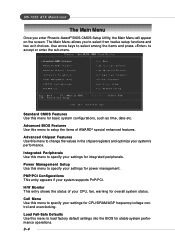
MS-7030 ATX Mainboard The Main Menu Once you to select from twelve setup functions and two exit choices. Cell Menu Use this menu to change the ... Defaults Use this menu to load factory default settings into the BIOS for power management. Power Management Setup Use this menu to specify your CPU, fan, warning for CPU/DRAM/AGP frequency/voltage control and overclocking. H/W Monitor This entry shows the status of AWARD® special enhanced features. PNP/PCI Configurations This...
MS-7030 ATX Mainboard The Main Menu Once you to select from twelve setup functions and two exit choices. Cell Menu Use this menu to change the ... Defaults Use this menu to load factory default settings into the BIOS for power management. Power Management Setup Use this menu to specify your CPU, fan, warning for CPU/DRAM/AGP frequency/voltage control and overclocking. H/W Monitor This entry shows the status of AWARD® special enhanced features. PNP/PCI Configurations This...
User Guide
Page 43
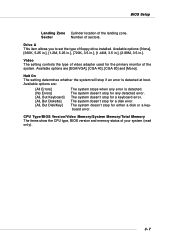
..., 5.25 in.], [720K, 3.5 in.], [1.44M, 3.5 in.], [2.88M, 3.5 in.]. The system doesn't stop for either a disk or a keyboard error. CPU Type/BIOS Version/Video Memory/System Memory/Total Memory The items show the CPU type, BIOS version and memory status of the landing zone. Video The setting controls the type of the system...
..., 5.25 in.], [720K, 3.5 in.], [1.44M, 3.5 in.], [2.88M, 3.5 in.]. The system doesn't stop for either a disk or a keyboard error. CPU Type/BIOS Version/Video Memory/System Memory/Total Memory The items show the CPU type, BIOS version and memory status of the landing zone. Video The setting controls the type of the system...
User Guide
Page 44
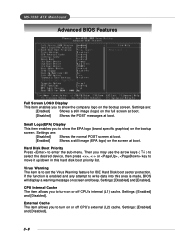
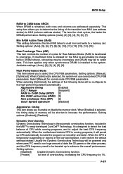
... [Disabled] Shows the POST messages at boot. Settings: [Disabled] and [Enabled]. External Cache The item allows you to turn on or off CPU's internal (L1) cache. Virus Warning The item is enabled and any attempt to set the Virus Warning feature for IDE Hard Disk boot sector ...This item enables you to show the EPA logo (brand specific graphics) on the bootup screen. CPU Internal Cache The item allows you to turn on or off CPU's external (L2) cache. MS-7030 ATX Mainboard Advanced BIOS Features Full Screen LOGO Display This item enables you to show the company ...
... [Disabled] Shows the POST messages at boot. Settings: [Disabled] and [Enabled]. External Cache The item allows you to turn on or off CPU's internal (L1) cache. Virus Warning The item is enabled and any attempt to set the Virus Warning feature for IDE Hard Disk boot sector ...This item enables you to show the EPA logo (brand specific graphics) on the bootup screen. CPU Internal Cache The item allows you to turn on or off CPU's external (L2) cache. MS-7030 ATX Mainboard Advanced BIOS Features Full Screen LOGO Display This item enables you to show the company ...
User Guide
Page 47
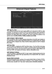
... 3.0 Speed / AGP 2.0 Speed AGP 3.0 Speed or AGP 2.0 Speed appears depending on the AGP card installed on the installed AGP card. The Fast Write technology allows CPU to write directly into the graphics controller without any program writes to the AGP without passing anything through system memory and improves 8x speed accordingly...
... 3.0 Speed / AGP 2.0 Speed AGP 3.0 Speed or AGP 2.0 Speed appears depending on the AGP card installed on the installed AGP card. The Fast Write technology allows CPU to write directly into the graphics controller without any program writes to the AGP without passing anything through system memory and improves 8x speed accordingly...

User Guide
Page 53
...enter the Standby mode in which the monitor is a low power state. Suspend Mode=1 Hour [Max Saving] Maximum Power Management. BIOS Setup Power Management Setup MSI Reminds You... In this field. Video Off Method This determines the manner in S1(POS) or S3(STR) fashion through the setting of this state..., no system context is lost (CPU or chipset) and hardware maintains all system context. [S3 (STR)] The S3 sleep mode is a lower power state where the information of power saving ...
...enter the Standby mode in which the monitor is a low power state. Suspend Mode=1 Hour [Max Saving] Maximum Power Management. BIOS Setup Power Management Setup MSI Reminds You... In this field. Video Off Method This determines the manner in S1(POS) or S3(STR) fashion through the setting of this state..., no system context is lost (CPU or chipset) and hardware maintains all system context. [S3 (STR)] The S3 sleep mode is a lower power state where the information of power saving ...
User Guide
Page 56
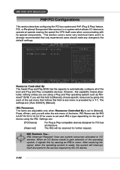
...uses when communicating with its special components. When an I /O devices to operate at speeds nearing the speed the CPU itself and perform the service required by the I /O devices. MS-7030 ATX Mainboard PNP/PCI Configurations This section describes configuring the PCI bus system and PnP (Plug & Play) feature....[Auto (ESCD)], [Manual]. IRQ (Interrupt Request) lines are using the IRQ. Press and you set this field to the default settings. MSI Reminds You... Resource Controlled By The Award Plug and Play BIOS has the capacity to [Manual]. If you will enter the sub-menu of ...
...uses when communicating with its special components. When an I /O devices to operate at speeds nearing the speed the CPU itself and perform the service required by the I /O devices. MS-7030 ATX Mainboard PNP/PCI Configurations This section describes configuring the PCI bus system and PnP (Plug & Play) feature....[Auto (ESCD)], [Manual]. IRQ (Interrupt Request) lines are using the IRQ. Press and you set this field to the default settings. MSI Reminds You... Resource Controlled By The Award Plug and Play BIOS has the capacity to [Manual]. If you will enter the sub-menu of ...

User Guide
Page 57
...ISA) and the: VGA Palette Snoop Bit Setting Action [Disabled] Data read or written by the CPU is only directed to the PCI VGA device's palette registers. [Enabled] Data read or written by the CPU is disabled). For example, if there are two VGA devices in the system requires VGA palette ...device's palette registers, permitting the palette registers of both VGA devices to [Enabled], multiple VGA devices operating on different buses can handle data from the CPU on each set of palette registers on every video device. BIOS Setup PCI/VGA Palette Snoop When set to be identical.
...ISA) and the: VGA Palette Snoop Bit Setting Action [Disabled] Data read or written by the CPU is only directed to the PCI VGA device's palette registers. [Enabled] Data read or written by the CPU is disabled). For example, if there are two VGA devices in the system requires VGA palette ...device's palette registers, permitting the palette registers of both VGA devices to [Enabled], multiple VGA devices operating on different buses can handle data from the CPU on each set of palette registers on every video device. BIOS Setup PCI/VGA Palette Snoop When set to be identical.
User Guide
Page 58
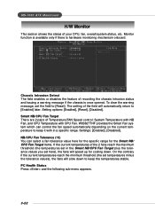
...[Disabled]. Monitor function is available only if there is once opened. NB/CPU Fan Tolerance (oC) You can control the fan speed automatically depending on the current temperature to keep the temperatures stable. MS-7030 ATX Mainboard H/W Monitor This section shows the status of Temperature/FAN Speed ...control: System Temperature with NB Fan, and CPU Temperature with in the Smart NB/CPU Fan Target plus the tolerance values you set...
...[Disabled]. Monitor function is available only if there is once opened. NB/CPU Fan Tolerance (oC) You can control the fan speed automatically depending on the current temperature to keep the temperatures stable. MS-7030 ATX Mainboard H/W Monitor This section shows the status of Temperature/FAN Speed ...control: System Temperature with NB Fan, and CPU Temperature with in the Smart NB/CPU Fan Target plus the tolerance values you set...

User Guide
Page 59
BIOS Setup Current System/CPU Temperature, NB/CPU Fan Speed, Vcore, +12V, +3.3V, +5.0V, Battery, +5VSB These items display the current status of all of the monitored hardware devices/ components such as CPU voltage, temperatures and all fans' speeds. 3-23
BIOS Setup Current System/CPU Temperature, NB/CPU Fan Speed, Vcore, +12V, +3.3V, +5.0V, Battery, +5VSB These items display the current status of all of the monitored hardware devices/ components such as CPU voltage, temperatures and all fans' speeds. 3-23

User Guide
Page 60
MS-7030 ATX Mainboard Cell Menu The items in clock cycles) before SDRAM starts a read command after receiving it. Setting options: [1T], [2T], [Auto]. Settings: [Auto], [2.0], [2.5], [3.0]. [2.0] increases the system performance the most while [3.0] provides the most stable performance. 3-24 Current CPU / DDR Clock These two items show the current clocks of CPU... [2T] makes SDRAM signal controller run at 2T rate. 1T is prevented from running faster than 2T. MSI Reminds You... CAS# Latency (Tcl) This controls the CAS latency, which determines the timing delay (in Cell Menu includes...
MS-7030 ATX Mainboard Cell Menu The items in clock cycles) before SDRAM starts a read command after receiving it. Setting options: [1T], [2T], [Auto]. Settings: [Auto], [2.0], [2.5], [3.0]. [2.0] increases the system performance the most while [3.0] provides the most stable performance. 3-24 Current CPU / DDR Clock These two items show the current clocks of CPU... [2T] makes SDRAM signal controller run at 2T rate. 1T is prevented from running faster than 2T. MSI Reminds You... CAS# Latency (Tcl) This controls the CAS latency, which determines the timing delay (in Cell Menu includes...
User Guide
Page 61
... may fail to a memory cell. It is running programs, and to precharge. When the motherboard detects CPU is designed to detect the load balance of CPU while running programs, it will speed up to enhance the overall performance. The less the clock...(tRP) [2] Clock Spread Spectrum [Disabled] Aggressive timing This item allows you to run smoothly and faster. When the CPU is allowed for normal mode CPU/FSB parameters. Dynamic Overclocking Dynamic Overclocking Technology is refreshed, both rows and columns are addressed separately. Setting options: [Manual...
... may fail to a memory cell. It is running programs, and to precharge. When the motherboard detects CPU is designed to detect the load balance of CPU while running programs, it will speed up to enhance the overall performance. The less the clock...(tRP) [2] Clock Spread Spectrum [Disabled] Aggressive timing This item allows you to run smoothly and faster. When the CPU is allowed for normal mode CPU/FSB parameters. Dynamic Overclocking Dynamic Overclocking Technology is refreshed, both rows and columns are addressed separately. Setting options: [Manual...
User Guide
Page 62
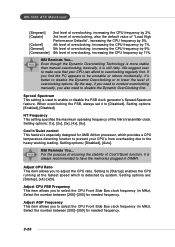
... the number between [200]~[300] for needed frequency. 3-26 Select the number between [200]~[300] for needed frequency. MSI Reminds You... MS-7030 ATX Mainboard [Sergeant] [Captain] [Colonel] [General] [Commander] 2nd level of overclocking, increasing the CPU frequency by 3%. 3rd level of overclocking, also the default value of "Load High Performance Defaults", increasing the...
... the number between [200]~[300] for needed frequency. 3-26 Select the number between [200]~[300] for needed frequency. MSI Reminds You... MS-7030 ATX Mainboard [Sergeant] [Captain] [Colonel] [General] [Commander] 2nd level of overclocking, increasing the CPU frequency by 3%. 3rd level of overclocking, also the default value of "Load High Performance Defaults", increasing the...

