User Manual
Page 13
JCOM1: Serial Port Connector 39 JBAT1: Clear CMOS (Reset BIOS) Jumper 40 JTBT1: Thunderbolt Add-on Card Connector 40 JRTD3: Intel RTD3 Connector 40 JRGB1: RGB LED connector 41 JRAINBOW1~2: Addressable RGB LED connectors 42 ... LED Control 44 Installing OS, Drivers & Utilities 45 Installing Windows® 10 45 Installing Drivers 45 Installing Utilities 45 UEFI BIOS...46 BIOS Setup...47 Entering BIOS Setup 47 Resetting BIOS...48 Updating BIOS...48 EZ Mode ...50 Advanced Mode ...53 SETTINGS Menu 54 OC Menu...56 M-FLASH Menu ...60 OC PROFILE Menu 61 HARDWARE...
JCOM1: Serial Port Connector 39 JBAT1: Clear CMOS (Reset BIOS) Jumper 40 JTBT1: Thunderbolt Add-on Card Connector 40 JRTD3: Intel RTD3 Connector 40 JRGB1: RGB LED connector 41 JRAINBOW1~2: Addressable RGB LED connectors 42 ... LED Control 44 Installing OS, Drivers & Utilities 45 Installing Windows® 10 45 Installing Drivers 45 Installing Utilities 45 UEFI BIOS...46 BIOS Setup...47 Entering BIOS Setup 47 Resetting BIOS...48 Updating BIOS...48 EZ Mode ...50 Advanced Mode ...53 SETTINGS Menu 54 OC Menu...56 M-FLASH Menu ...60 OC PROFILE Menu 61 HARDWARE...
User Manual
Page 15
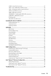
...up to PCIe 3.0 x4 and SATA 6Gb/s, 2242/ 2260/ 2280/ 22110 storage devices* ▪▪M2_2 supports up to the latest version from MSI website. Intel® Z490 Chipset ∙∙Supports RAID 0, RAID 1, RAID 5 and RAID 10 for SATA storage devices ∙∙Supports RAID 0 and RAID 1 ...when installing M.2 SSD in the M2_2 slot. *** Before using Intel® Optane™ memory modules, please ensure that you have updated the drivers and BIOS to PCIe 3.0 x4 and SATA 6Gb/s, 2242/ 2260/ 2280 storage devices** ▪▪Intel® Optane™ Memory Ready*** ▪▪Supports ...
...up to PCIe 3.0 x4 and SATA 6Gb/s, 2242/ 2260/ 2280/ 22110 storage devices* ▪▪M2_2 supports up to the latest version from MSI website. Intel® Z490 Chipset ∙∙Supports RAID 0, RAID 1, RAID 5 and RAID 10 for SATA storage devices ∙∙Supports RAID 0 and RAID 1 ...when installing M.2 SSD in the M2_2 slot. *** Before using Intel® Optane™ memory modules, please ensure that you have updated the drivers and BIOS to PCIe 3.0 x4 and SATA 6Gb/s, 2242/ 2260/ 2280 storage devices** ▪▪Intel® Optane™ Memory Ready*** ▪▪Supports ...
User Manual
Page 17
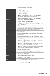
Continued from previous page LED Features Back Panel Connectors I/O Controller Hardware Monitor Form Factor BIOS Features Software ∙∙1x EZ LED Control switch ∙∙4x EZ Debug LED ∙∙1 x PS/2 keyboard/ mouse combo port ∙...;∙1x 256 Mb flash ∙∙UEFI AMI BIOS ∙∙ACPI 6.2, SMBIOS 3.2 ∙∙ Multi-language ∙∙ Drivers ∙∙DRAGON CENTER ∙∙MSI APP Player (BlueStacks) ∙∙Open Broadcaster Software (OBS) ∙∙CPU-Z MSI GAMING ∙∙Intel® Extreme Tuning Utility ∙...
Continued from previous page LED Features Back Panel Connectors I/O Controller Hardware Monitor Form Factor BIOS Features Software ∙∙1x EZ LED Control switch ∙∙4x EZ Debug LED ∙∙1 x PS/2 keyboard/ mouse combo port ∙...;∙1x 256 Mb flash ∙∙UEFI AMI BIOS ∙∙ACPI 6.2, SMBIOS 3.2 ∙∙ Multi-language ∙∙ Drivers ∙∙DRAGON CENTER ∙∙MSI APP Player (BlueStacks) ∙∙Open Broadcaster Software (OBS) ∙∙CPU-Z MSI GAMING ∙∙Intel® Extreme Tuning Utility ∙...

User Manual
Page 19
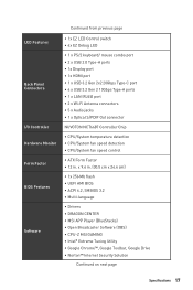
... previous page ∙∙ Performance ▪▪Multi GPU - CrossFire Technology ▪▪DDR4 Boost ▪▪Core Boost ▪▪Game Boost ▪▪Lightning USB 20G ▪▪USB 3.2 Gen 2 10G ▪▪USB with Type A+C ▪▪Front USB...;▪PCI-E Steel Armor X2 ▪▪Pre-installed I/O Shielding ∙∙ Experience ▪▪Dragon Center ▪▪Click BIOS 5 JCORSAIR1 Connector Specification Supporting CORSAIR RGB Products Lighting Node PRO LED Strip HD120 RGB Fan SP120 RGB Fan LL120 RGB Fan Maximum connection 20...
... previous page ∙∙ Performance ▪▪Multi GPU - CrossFire Technology ▪▪DDR4 Boost ▪▪Core Boost ▪▪Game Boost ▪▪Lightning USB 20G ▪▪USB 3.2 Gen 2 10G ▪▪USB with Type A+C ▪▪Front USB...;▪PCI-E Steel Armor X2 ▪▪Pre-installed I/O Shielding ∙∙ Experience ▪▪Dragon Center ▪▪Click BIOS 5 JCORSAIR1 Connector Specification Supporting CORSAIR RGB Products Lighting Node PRO LED Strip HD120 RGB Fan SP120 RGB Fan LL120 RGB Fan Maximum connection 20...
User Manual
Page 27
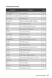
...~6 Fan Connectors CPU_PWR1~2, ATX_PWR1 Power Connectors CPU Socket LGA 1200 socket DIMM Slots DIMMA1, DIMMA2, DIMMB1, DIMMB2 JAUD1 Front Audio Connector JBAT1 Clear CMOS (Reset BIOS) Jumper JCI1 Chassis Intrusion Connector JCOM1 Serial Port Connector JCORSAIR1 CORSAIR Connector JFP1, JFP2 Front Panel Connectors JRAINBOW1~2 Addressable RGB LED connectors JRGB1 RGB LED...
...~6 Fan Connectors CPU_PWR1~2, ATX_PWR1 Power Connectors CPU Socket LGA 1200 socket DIMM Slots DIMMA1, DIMMA2, DIMMB1, DIMMB2 JAUD1 Front Audio Connector JBAT1 Clear CMOS (Reset BIOS) Jumper JCI1 Chassis Intrusion Connector JCOM1 Serial Port Connector JCORSAIR1 CORSAIR Connector JFP1, JFP2 Front Panel Connectors JRAINBOW1~2 Addressable RGB LED connectors JRGB1 RGB LED...

User Manual
Page 29
... memory. Overview of installed memory module depend on installed CPU and devices when overclocking. ∙∙Please refer www.msi.com for more information on its Serial Presence Detect (SPD). Go to BIOS and find the DRAM Frequency to set the memory frequency if you want to operate the memory at the...
... memory. Overview of installed memory module depend on installed CPU and devices when overclocking. ∙∙Please refer www.msi.com for more information on its Serial Presence Detect (SPD). Go to BIOS and find the DRAM Frequency to set the memory frequency if you want to operate the memory at the...
User Manual
Page 38
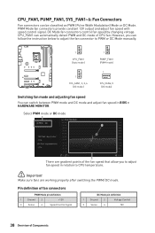
... Control 3 Sense 4 NC 38 Overview of the fan speed that allow you can switch between PWM mode and DC mode and adjust fan speed in BIOS > HARDWARE MONITOR. CPU_FAN1, PUMP_FAN1, SYS_FAN1~6: Fan Connectors Fan connectors can automatically detect PWM and DC mode of CPU fan. DC Mode fan connectors control fan...
... Control 3 Sense 4 NC 38 Overview of the fan speed that allow you can switch between PWM mode and DC mode and adjust fan speed in BIOS > HARDWARE MONITOR. CPU_FAN1, PUMP_FAN1, SYS_FAN1~6: Fan Connectors Fan connectors can automatically detect PWM and DC mode of CPU fan. DC Mode fan connectors control fan...

User Manual
Page 39
...the chassis cover. 3. Go to Reset. 3. Press F10 to save and exit and then press the Enter key to select Yes. Set Chassis Intrusion to BIOS > SETTINGS > Security > Chassis Intrusion Configuration. 4. Resetting the chassis intrusion warning 1. Press F10 to save and exit and then press the Enter key ... to the chassis intrusion switch/ sensor on . JCOM1: Serial Port Connector This connector allows you to Enabled. 5. Connect the JCI1 connector to BIOS > SETTINGS > Security > Chassis Intrusion Configuration. 2. Set Chassis Intrusion to connect the chassis intrusion switch cable.
...the chassis cover. 3. Go to Reset. 3. Press F10 to save and exit and then press the Enter key to select Yes. Set Chassis Intrusion to BIOS > SETTINGS > Security > Chassis Intrusion Configuration. 4. Resetting the chassis intrusion warning 1. Press F10 to save and exit and then press the Enter key ... to the chassis intrusion switch/ sensor on . JCOM1: Serial Port Connector This connector allows you to Enabled. 5. Connect the JCI1 connector to BIOS > SETTINGS > Security > Chassis Intrusion Configuration. 2. Set Chassis Intrusion to connect the chassis intrusion switch cable.
User Manual
Page 40
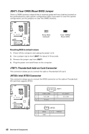
...the add-on Thunderbolt I /O card. Power off the computer and unplug the power cord. 2. Keep Data (default) Clear CMOS/ Reset BIOS Resetting BIOS to short JBAT1 for about 5-10 seconds. 3. Use a jumper cap to default values 1. Remove the jumper cap from a battery located... on the computer. JBAT1: Clear CMOS (Reset BIOS) Jumper There is CMOS memory onboard that supports RTD3. 1 JTBT1 1 FORCE_PWR 2 3 SLP_S3# 4 5 Ground SCI_EVENT SLP_S5# 1 JRTD3 1 WAKE 2 PWR...
...the add-on Thunderbolt I /O card. Power off the computer and unplug the power cord. 2. Keep Data (default) Clear CMOS/ Reset BIOS Resetting BIOS to short JBAT1 for about 5-10 seconds. 3. Use a jumper cap to default values 1. Remove the jumper cap from a battery located... on the computer. JBAT1: Clear CMOS (Reset BIOS) Jumper There is CMOS memory onboard that supports RTD3. 1 JTBT1 1 FORCE_PWR 2 3 SLP_S3# 4 5 Ground SCI_EVENT SLP_S5# 1 JRTD3 1 WAKE 2 PWR...
User Manual
Page 46
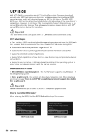
.... Incompatible UEFI cases ∙∙ 32-bit Windows operating system - the system will completely replace BIOS in this user guide refers to check the BIOS mode? UEFI BIOS MSI UEFI BIOS is no malware tampers with UEFI (Unified Extensible Firmware Interface) architecture. However, it will detect your...;∙Supports for hard drive partitions larger than 2 TB. ∙∙Supports more than 4 primary partitions with older devices. The MSI UEFI BIOS uses UEFI as the default boot mode to be compatible with a GUID Partition Table (GPT). ∙∙Supports unlimited number of ...
.... Incompatible UEFI cases ∙∙ 32-bit Windows operating system - the system will completely replace BIOS in this user guide refers to check the BIOS mode? UEFI BIOS MSI UEFI BIOS is no malware tampers with UEFI (Unified Extensible Firmware Interface) architecture. However, it will detect your...;∙Supports for hard drive partitions larger than 2 TB. ∙∙Supports more than 4 primary partitions with older devices. The MSI UEFI BIOS uses UEFI as the default boot mode to be compatible with a GUID Partition Table (GPT). ∙∙Supports unlimited number of ...

User Manual
Page 47
...are continuously update for better system performance. You could also refer to the HELP information panel for BIOS item description. ∙∙The pictures in normal conditions. BIOS Setup The default settings offer the optimal performance for system stability in this chapter are for reference...only and may be for reference only. Ctrl+F: Enter Search page * When you purchased. ∙∙The BIOS items will vary with BIOS. ⚠⚠Important ∙∙BIOS items are familiar with the processor. You should be slightly different from the product you press F10, a ...
...are continuously update for better system performance. You could also refer to the HELP information panel for BIOS item description. ∙∙The pictures in normal conditions. BIOS Setup The default settings offer the optimal performance for system stability in this chapter are for reference...only and may be for reference only. Ctrl+F: Enter Search page * When you purchased. ∙∙The BIOS items will vary with BIOS. ⚠⚠Important ∙∙BIOS items are familiar with the processor. You should be slightly different from the product you press F10, a ...
User Manual
Page 48
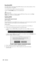
...;Short the Clear CMOS jumper on Yes to reboot the system. 3. Updating BIOS: 1. After the flashing process is off before clearing CMOS data. Insert the USB flash drive that matches your motherboard model from MSI website. Click the M-FLASH button and click on the motherboard. ⚠⚠...;Important Be sure the computer is 100% completed, the system will reboot automatically. 48 UEFI BIOS Please refer to the Clear CMOS jumper section for BIOS update. ▪▪...
...;Short the Clear CMOS jumper on Yes to reboot the system. 3. Updating BIOS: 1. After the flashing process is off before clearing CMOS data. Insert the USB flash drive that matches your motherboard model from MSI website. Click the M-FLASH button and click on the motherboard. ⚠⚠...;Important Be sure the computer is 100% completed, the system will reboot automatically. 48 UEFI BIOS Please refer to the Clear CMOS jumper section for BIOS update. ▪▪...

User Manual
Page 49
... Live Update and click on Download icon to Support page. 2. Select the BIOS file and click on Advance button. 3. Install and launch MSI DRAGON CENTER and go to download and install the latest BIOS file. 5. UEFI BIOS 49 Updating BIOS: 1. Updating the BIOS with MSI DRAGON CENTER Before updating: Make sure the LAN driver is already installed...
... Live Update and click on Download icon to Support page. 2. Select the BIOS file and click on Advance button. 3. Install and launch MSI DRAGON CENTER and go to download and install the latest BIOS file. 5. UEFI BIOS 49 Updating BIOS: 1. Updating the BIOS with MSI DRAGON CENTER Before updating: Make sure the LAN driver is already installed...
User Manual
Page 50
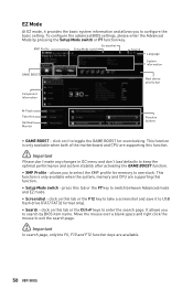
..., please enter the Advanced Mode by BIOS item name. XMP Profile Screenshot Setup Mode switch Search Language System information GAME BOOST Boot device priority bar Component Information M-Flash Favorites Hardware Monitor Function buttons ∙∙ GAME BOOST - Move the mouse over a blank space and right click the ...the motherboard and CPU are supporting this tab or the Ctrl+F keys to enter the search page. click on it to toggle the GAME BOOST for memory to overclock. click on this function. ⚠⚠Important Please don't make any changes in OC menu and don...
..., please enter the Advanced Mode by BIOS item name. XMP Profile Screenshot Setup Mode switch Search Language System information GAME BOOST Boot device priority bar Component Information M-Flash Favorites Hardware Monitor Function buttons ∙∙ GAME BOOST - Move the mouse over a blank space and right click the ...the motherboard and CPU are supporting this tab or the Ctrl+F keys to enter the search page. click on it to toggle the GAME BOOST for memory to overclock. click on this function. ⚠⚠Important Please don't make any changes in OC menu and don...
User Manual
Page 51
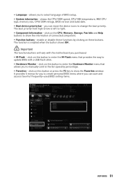
... Favorites - ∙∙ Language - shows the CPU/ DDR speed, CPU/ MB temperature, MB/ CPU type, memory size, CPU/ DDR voltage, BIOS version and build date. ∙∙ Boot device priority bar - click on this button or press the F3 key to change the boot priority. It... provides 5 menus for you to select language of connected component. ∙∙ Function buttons - you to create personal BIOS menu where you purchased. ∙∙ M-Flash - click on the CPU, Memory, Storage, Fan Info and Help buttons to right. ∙∙...
... Favorites - ∙∙ Language - shows the CPU/ DDR speed, CPU/ MB temperature, MB/ CPU type, memory size, CPU/ DDR voltage, BIOS version and build date. ∙∙ Boot device priority bar - click on this button or press the F3 key to change the boot priority. It... provides 5 menus for you to select language of connected component. ∙∙ Function buttons - you to create personal BIOS menu where you purchased. ∙∙ M-Flash - click on the CPU, Memory, Storage, Fan Info and Help buttons to right. ∙∙...

User Manual
Page 52
Choose a favorite page and click on OK. 52 UEFI BIOS Choose Delete and click on OK. ▪▪To delete a BIOS item from favorite menu 1. Select a BIOS item on search page. 2. Select a BIOS item not only on BIOS menu but also on favorite menu. 2. Right-click or press F2 key. 3. ▪▪To add a BIOS item to a favorite menu 1. Right-click or press F2 key. 3.
Choose a favorite page and click on OK. 52 UEFI BIOS Choose Delete and click on OK. ▪▪To delete a BIOS item from favorite menu 1. Select a BIOS item on search page. 2. Select a BIOS item not only on BIOS menu but also on favorite menu. 2. Right-click or press F2 key. 3. ▪▪To add a BIOS item to a favorite menu 1. Right-click or press F2 key. 3.
User Manual
Page 53
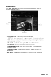
... ▪▪HARDWARE MONITOR - allows you to adjust the frequency and voltage. allows you to update BIOS with a USB flash drive. ▪▪OC PROFILE - provides BIOS setting items and information to set the speeds of fans and monitor voltages of installed devices on this ...∙∙ Menu display - Advanced Mode Press Setup Mode switch or F7 function key can switch between EZ Mode and Advanced Mode in BIOS setup. the following options are available: ▪▪SETTINGS - Increasing the frequency may get better performance. ▪▪M-FLASH - allows you...
... ▪▪HARDWARE MONITOR - allows you to adjust the frequency and voltage. allows you to update BIOS with a USB flash drive. ▪▪OC PROFILE - provides BIOS setting items and information to set the speeds of fans and monitor voltages of installed devices on this ...∙∙ Menu display - Advanced Mode Press Setup Mode switch or F7 function key can switch between EZ Mode and Advanced Mode in BIOS setup. the following options are available: ▪▪SETTINGS - Increasing the frequency may get better performance. ▪▪M-FLASH - allows you...
User Manual
Page 54
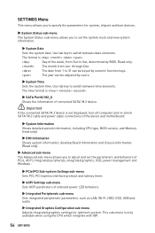
...Sets the system time. The month from 1 to 31 can be keyed by numeric function keys. The year can be adjusted by BIOS. The date from Jan. SETTINGS Menu This menu allows you to set the parameters and behaviors of PCIe, ACPI, integrated peripherals, ...SATA/ M.2 cable and power cable connections of the device and motherboard. ▶▶System Information Shows detailed system information, including CPU type, BIOS version, and Memory (read only). ▶▶DMI Information Shows system information, desktop Board Information and chassis Information. (Read only). ▶...
...Sets the system time. The month from 1 to 31 can be keyed by numeric function keys. The year can be adjusted by BIOS. The date from Jan. SETTINGS Menu This menu allows you to set the parameters and behaviors of PCIe, ACPI, integrated peripherals, ...SATA/ M.2 cable and power cable connections of the device and motherboard. ▶▶System Information Shows detailed system information, including CPU type, BIOS version, and Memory (read only). ▶▶DMI Information Shows system information, desktop Board Information and chassis Information. (Read only). ▶...
User Manual
Page 55
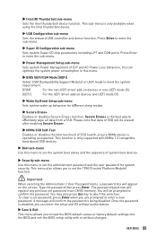
.... This function is disabled, you are prompted to abort the selection. A message will be prompted to effectively wipe all data from CMOS memory. UEFI BIOS 55 Press Enter to meet the system requirement. [CSM] For the non-UEFI driver add-on devices or non-UEFI mode OS. [UEFI] For ...enter the setup and OS without changes. Please note that data of system boot devices. ▶▶Security sub-menu Use this menu. ▶▶BIOS UEFI/CSM Mode [UEFI] Select CSM (Compatibility Support Module) or UEFI mode to enter the sub-menu. ▶▶Super IO Configuration sub-menu...
.... This function is disabled, you are prompted to abort the selection. A message will be prompted to effectively wipe all data from CMOS memory. UEFI BIOS 55 Press Enter to meet the system requirement. [CSM] For the non-UEFI driver add-on devices or non-UEFI mode OS. [UEFI] For ...enter the setup and OS without changes. Please note that data of system boot devices. ▶▶Security sub-menu Use this menu. ▶▶BIOS UEFI/CSM Mode [UEFI] Select CSM (Compatibility Support Module) or UEFI mode to enter the sub-menu. ▶▶Super IO Configuration sub-menu...
User Manual
Page 56
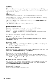
Note: We use GAME BOOST function for the OC settings of active cores. This item only appears when ... Sets the number of CPU cores as the symbol for easy overclocking. ∙∙The BIOS items in CPU core number. Read-only. 56 UEFI BIOS These items only appear when CPU Ratio Apply Mode set the CPU ratios for different number of...] Enables or disables to show the normal or expert version of OC settings. [Normal] Provides the regular OC settings in BIOS setup. These items only appear when CPU Ratio Apply Mode set to Turbo Ratio. ▶▶Target CPU Turbo Ratio Group...
Note: We use GAME BOOST function for the OC settings of active cores. This item only appears when ... Sets the number of CPU cores as the symbol for easy overclocking. ∙∙The BIOS items in CPU core number. Read-only. 56 UEFI BIOS These items only appear when CPU Ratio Apply Mode set the CPU ratios for different number of...] Enables or disables to show the normal or expert version of OC settings. [Normal] Provides the regular OC settings in BIOS setup. These items only appear when CPU Ratio Apply Mode set to Turbo Ratio. ▶▶Target CPU Turbo Ratio Group...


