User Manual
Page 1
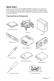
... on your computer. This Quick Start section provides demonstration diagrams about how to install your phone or tablet. Quick Start Thank you for purchasing the MSI® MEG Z490 UNIFY motherboard. Some of Screws Quick Start 1
... on your computer. This Quick Start section provides demonstration diagrams about how to install your phone or tablet. Quick Start Thank you for purchasing the MSI® MEG Z490 UNIFY motherboard. Some of Screws Quick Start 1
User Manual
Page 2
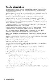
... connecting the PSU to ensure successful computer assembly. ∙∙Ensure that there are no loose screws or metal components on the motherboard should be noted. ∙∙If any computer component. ∙∙Keep this user guide for future reference. ∙∙Keep this...above 60°C (140°F), it may cause the computer to not recognize a component or fail to start. ∙∙Hold the motherboard by touching another metal object before installation is indicated on it. If an ESD wrist strap is not available, discharge yourself of static electricity by...
... connecting the PSU to ensure successful computer assembly. ∙∙Ensure that there are no loose screws or metal components on the motherboard should be noted. ∙∙If any computer component. ∙∙Keep this user guide for future reference. ∙∙Keep this...above 60°C (140°F), it may cause the computer to not recognize a component or fail to start. ∙∙Hold the motherboard by touching another metal object before installation is indicated on it. If an ESD wrist strap is not available, discharge yourself of static electricity by...

User Manual
Page 6
Installing the Motherboard 1 ⚽ ⚽ https://youtu.be/wWI6Qt51Wnc Torque: 3 kgf·cm* 2 *3 kgf·cm = 0.3 N·m = 2.6 lbf·in 6 Safety Information
Installing the Motherboard 1 ⚽ ⚽ https://youtu.be/wWI6Qt51Wnc Torque: 3 kgf·cm* 2 *3 kgf·cm = 0.3 N·m = 2.6 lbf·in 6 Safety Information
User Manual
Page 12
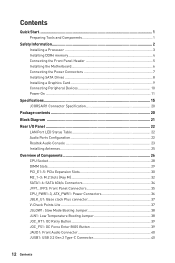
Contents Quick Start...1 Preparing Tools and Components 1 Safety Information 2 Installing a Processor 3 Installing DDR4 memory 4 Connecting the Front Panel Header 5 Installing the Motherboard 6 Connecting the Power Connectors 7 Installing SATA Drives 8 Installing a Graphics Card 9 Connecting Peripheral Devices 10 Power On...11 Specifications...15 JCORSAIR1 Connector Specification 20 Package contents ...
Contents Quick Start...1 Preparing Tools and Components 1 Safety Information 2 Installing a Processor 3 Installing DDR4 memory 4 Connecting the Front Panel Header 5 Installing the Motherboard 6 Connecting the Power Connectors 7 Installing SATA Drives 8 Installing a Graphics Card 9 Connecting Peripheral Devices 10 Power On...11 Specifications...15 JCORSAIR1 Connector Specification 20 Package contents ...
User Manual
Page 20
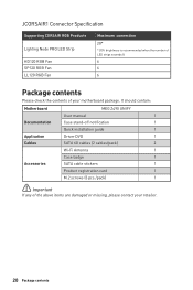
It should contain: Motherboard MEG Z490 UNIFY User manual 1 Documentation Case stand-off notification 1 Quick installation guide 1 Application Driver DVD 1 Cables SATA 6G cables (2 cables/pack) 2 Wi-Fi Antenna 1 Case badge 1 Accessories ... recommended when the number of LED strips exceeds 8. 6 6 6 Package contents Please check the contents of the above items are damaged or missing, please contact your motherboard package.
It should contain: Motherboard MEG Z490 UNIFY User manual 1 Documentation Case stand-off notification 1 Quick installation guide 1 Application Driver DVD 1 Cables SATA 6G cables (2 cables/pack) 2 Wi-Fi Antenna 1 Case badge 1 Accessories ... recommended when the number of LED strips exceeds 8. 6 6 6 Package contents Please check the contents of the above items are damaged or missing, please contact your motherboard package.

User Manual
Page 28
...necessary to prevent overheating and maintain system stability. ∙∙Confirm that all other system components can seriously damage the CPU and motherboard. MSI® does not guarantee the damages or risks caused by covering the socket with the plastic cap. ∙∙If you ... in correctly lining up the CPU for more details about installation. ∙∙This motherboard is not recommended. MSI will deal with Return Merchandise Authorization (RMA) requests if only the motherboard comes with the CPU before installing or removing the CPU. ∙∙Please retain...
...necessary to prevent overheating and maintain system stability. ∙∙Confirm that all other system components can seriously damage the CPU and motherboard. MSI® does not guarantee the damages or risks caused by covering the socket with the plastic cap. ∙∙If you ... in correctly lining up the CPU for more details about installation. ∙∙This motherboard is not recommended. MSI will deal with Return Merchandise Authorization (RMA) requests if only the motherboard comes with the CPU before installing or removing the CPU. ∙∙Please retain...

User Manual
Page 34
Each connector can connect to the motherboard for space saving purposes. ∙∙SATA2 will be connected to one SATA device. Data loss may result during transmission otherwise. ∙∙SATA cables ...
Each connector can connect to the motherboard for space saving purposes. ∙∙SATA2 will be connected to one SATA device. Data loss may result during transmission otherwise. ∙∙SATA cables ...
User Manual
Page 36
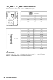
... Ground ⚠⚠Important Make sure that all the power cables are securely connected to a proper ATX power supply to ensure stable operation of the motherboard. 36 Overview of Components
... Ground ⚠⚠Important Make sure that all the power cables are securely connected to a proper ATX power supply to ensure stable operation of the motherboard. 36 Overview of Components

User Manual
Page 46
... of Components Keep Data (default) Clear CMOS/ Reset BIOS Resetting BIOS to save system configuration data. Remove the jumper cap from a battery located on the motherboard to default values 1. JBAT1: Clear CMOS (Reset BIOS) Jumper There is CMOS memory onboard that is external powered from JBAT1. 4. POWER1, RESET1: Power Button, Reset...
... of Components Keep Data (default) Clear CMOS/ Reset BIOS Resetting BIOS to save system configuration data. Remove the jumper cap from a battery located on the motherboard to default values 1. JBAT1: Clear CMOS (Reset BIOS) Jumper There is CMOS memory onboard that is external powered from JBAT1. 4. POWER1, RESET1: Power Button, Reset...

User Manual
Page 49
... between models. Any fan not connected in series. 1 > 2 > 3 > 4 > 5 > 6. Once all items are connected properly, you to the motherboard specification. ∙∙CORSAIR RGB LED Fan and CORSAIR Lighting Node PRO can control the CORSAIR RGB LED strips and fans with the CORSAIR fan... hub. Please refer to connect the CORSAIR Individually Addressable Lighting PRO RGB LED strips 5V or CORSAIR RGB fans with MSI's software. 1 JCORSAIR1 1 +5V 2 3 Ground Data CORSAIR RGB Fan Connection CORSAIR RGB LED fan SATA power SYS_FAN SYS_FAN CORSAIR fan hub 4 5 ...
... between models. Any fan not connected in series. 1 > 2 > 3 > 4 > 5 > 6. Once all items are connected properly, you to the motherboard specification. ∙∙CORSAIR RGB LED Fan and CORSAIR Lighting Node PRO can control the CORSAIR RGB LED strips and fans with the CORSAIR fan... hub. Please refer to connect the CORSAIR Individually Addressable Lighting PRO RGB LED strips 5V or CORSAIR RGB fans with MSI's software. 1 JCORSAIR1 1 +5V 2 3 Ground Data CORSAIR RGB Fan Connection CORSAIR RGB LED fan SATA power SYS_FAN SYS_FAN CORSAIR fan hub 4 5 ...

User Manual
Page 50
XMP LED This LED indicates the XMP (Extreme Memory Profile) mode is used by retailers to demonstrate onboard LED lights. XMP LED JPWRLED1: LED power input This connector is enabled. LED power input 50 Onboard LEDs indicates DRAM is not detected or fail. BOOT - indicates CPU is not detected or fail. indicates GPU is not detected or fail. indicates the booting device is not detected or fail. JPWRLED1 - CPU - DRAM - Onboard LEDs EZ Debug LED These LEDs indicate the debug status of the motherboard. VGA -
XMP LED This LED indicates the XMP (Extreme Memory Profile) mode is used by retailers to demonstrate onboard LED lights. XMP LED JPWRLED1: LED power input This connector is enabled. LED power input 50 Onboard LEDs indicates DRAM is not detected or fail. BOOT - indicates CPU is not detected or fail. indicates GPU is not detected or fail. indicates the booting device is not detected or fail. JPWRLED1 - CPU - DRAM - Onboard LEDs EZ Debug LED These LEDs indicate the debug status of the motherboard. VGA -
User Manual
Page 51
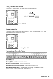
Refer to switch on/ off all the LEDs of motherboard. main hardware initialization Boot Device Selection (BDS) - initial low-level initialization Pre-EFI Initialization (PEI) - Debug Code LED Hexadecimal Character Table Hexadecimal 0 1 2 3 4 5 6 7 8 9 A B C D E F Debug Code LED ...
Refer to switch on/ off all the LEDs of motherboard. main hardware initialization Boot Device Selection (BDS) - initial low-level initialization Pre-EFI Initialization (PEI) - Debug Code LED Hexadecimal Character Table Hexadecimal 0 1 2 3 4 5 6 7 8 9 A B C D E F Debug Code LED ...

User Manual
Page 58
... BIOS unless otherwise noted. When display a warning message There is compatible with UEFI (Unified Extensible Firmware Interface) architecture. After entering the BIOS, find the BIOS Mode at the... top of the operating system to check the BIOS mode? UEFI BIOS MSI UEFI BIOS is no malware tampers with the startup process. And also eliminates the time...detected in this graphics card. ⚠⚠Important We recommend that traditional BIOS cannot achieve. this motherboard supports only 64-bit Windows 10 operating system. ∙∙ Older graphics card - Incompatible ...
... BIOS unless otherwise noted. When display a warning message There is compatible with UEFI (Unified Extensible Firmware Interface) architecture. After entering the BIOS, find the BIOS Mode at the... top of the operating system to check the BIOS mode? UEFI BIOS MSI UEFI BIOS is no malware tampers with the startup process. And also eliminates the time...detected in this graphics card. ⚠⚠Important We recommend that traditional BIOS cannot achieve. this motherboard supports only 64-bit Windows 10 operating system. ∙∙ Older graphics card - Incompatible ...

User Manual
Page 60
...reset BIOS: ∙∙Go to BIOS and press F6 to load optimized defaults. ∙∙Short the Clear CMOS jumper on the motherboard. ⚠⚠Important Be sure the computer is 100% completed, the system will reboot automatically. 60 UEFI BIOS Click the M-FLASH button...to start recovering BIOS. 5. After the flashing process is off before clearing CMOS data. Insert the USB flash drive that matches your motherboard model from MSI website. Updating BIOS: 1. When prompted click on Yes to reboot the system. Updating BIOS Updating BIOS with M-FLASH Before updating: Please...
...reset BIOS: ∙∙Go to BIOS and press F6 to load optimized defaults. ∙∙Short the Clear CMOS jumper on the motherboard. ⚠⚠Important Be sure the computer is 100% completed, the system will reboot automatically. 60 UEFI BIOS Click the M-FLASH button...to start recovering BIOS. 5. After the flashing process is off before clearing CMOS data. Insert the USB flash drive that matches your motherboard model from MSI website. Updating BIOS: 1. When prompted click on Yes to reboot the system. Updating BIOS Updating BIOS with M-FLASH Before updating: Please...
User Manual
Page 61
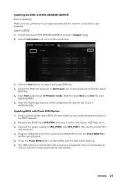
... start updating BIOS. 6. Click on Scan button to achieve by reset button. And then click Next and Start to the root of your motherboard model from the MSI® website. 2. Connect the power supply to CPU_PWR1 and ATX_PWR1. (No need to flash BIOS, and the LED starts flashing. 6. Updating... BIOS file. 5. Updating the BIOS with Flash BIOS Button 1. Select the BIOS file and click on Advance button. 3. Updating BIOS with MSI DRAGON CENTER Before updating: Make sure the LAN driver is already installed and the internet connection is 100% completed, the system will be turned...
... start updating BIOS. 6. Click on Scan button to achieve by reset button. And then click Next and Start to the root of your motherboard model from the MSI® website. 2. Connect the power supply to CPU_PWR1 and ATX_PWR1. (No need to flash BIOS, and the LED starts flashing. 6. Updating... BIOS file. 5. Updating the BIOS with Flash BIOS Button 1. Select the BIOS file and click on Advance button. 3. Updating BIOS with MSI DRAGON CENTER Before updating: Make sure the LAN driver is already installed and the internet connection is 100% completed, the system will be turned...

User Manual
Page 62
... (FAT/ FAT32 format only). ∙∙ Search - allows you to select the XMP profile for overclocking. This function is only available when both of the motherboard and CPU are supporting this function. ∙∙ Setup Mode switch - click on this tab or the F12 key to take a screenshot and save it...
... (FAT/ FAT32 format only). ∙∙ Search - allows you to select the XMP profile for overclocking. This function is only available when both of the motherboard and CPU are supporting this function. ∙∙ Setup Mode switch - click on this tab or the F12 key to take a screenshot and save it...
User Manual
Page 63
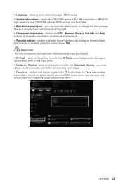
.... The function is left to change the boot priority. click on the CPU, Memory, Storage, Fan Info and Help buttons to update BIOS with the motherboard you to show the information of BIOS setup. ∙∙ System information - It provides 5 menus for you can move the device icons to right. ∙...
.... The function is left to change the boot priority. click on the CPU, Memory, Storage, Fan Info and Help buttons to update BIOS with the motherboard you to show the information of BIOS setup. ∙∙ System information - It provides 5 menus for you can move the device icons to right. ∙...

User Manual
Page 65
allows you to adjust the frequency and voltage. allows you to set the speeds of fans and monitor voltages of installed devices on this motherboard. ∙∙ Menu display - BIOS menu selection BIOS menu selection Menu display ∙∙ BIOS menu selection - provides the way to manage overclocking profiles. ▪&#...
allows you to adjust the frequency and voltage. allows you to set the speeds of fans and monitor voltages of installed devices on this motherboard. ∙∙ Menu display - BIOS menu selection BIOS menu selection Menu display ∙∙ BIOS menu selection - provides the way to manage overclocking profiles. ▪&#...
User Manual
Page 66
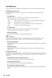
... information. ▶▶System Date Sets the system date. The time format is . ▶▶SATA PortX/ M2_X Shows the information of the device and motherboard. ▶▶System Information Shows detailed system information, including CPU type, BIOS version, and Memory (read only). ▶▶DMI Information Shows system information, desktop...
... information. ▶▶System Date Sets the system date. The time format is . ▶▶SATA PortX/ M2_X Shows the information of the device and motherboard. ▶▶System Information Shows detailed system information, including CPU type, BIOS version, and Memory (read only). ▶▶DMI Information Shows system information, desktop...

User Manual
Page 72
... to reboot and enter the flash mode. 3. Click on M-FLASH tab, a demand message will be prompted. Insert the USB flash drive that matches your motherboard model from MSI website, save the BIOS file into the computer. 2. The system will enter the flash mode and a file selection menu will reboot automatically. 72 UEFI...
... to reboot and enter the flash mode. 3. Click on M-FLASH tab, a demand message will be prompted. Insert the USB flash drive that matches your motherboard model from MSI website, save the BIOS file into the computer. 2. The system will enter the flash mode and a file selection menu will reboot automatically. 72 UEFI...


