User Manual
Page 12
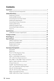
... a Processor 3 Installing DDR4 memory 4 Connecting the Front Panel Header 5 Installing the Motherboard 6 Connecting the Power Connectors 7 Installing SATA Drives 8 Installing a Graphics Card 9 Connecting Peripheral Devices 10 Power On...11 Specifications...15 JCORSAIR1 Connector Specification 20 Package contents 20 Block Diagram ...21 Rear I/O Panel...22 LAN Port LED Status Table 22 Audio Ports Configuration 22 Realtek Audio Console 23 Installing Antennas 25 Overview of Components 26 CPU Socket...28 DIMM Slots...29 PCI_E1~5: PCIe Expansion Slots 30 M2_1~3: M.2 Slots (Key M 32...
... a Processor 3 Installing DDR4 memory 4 Connecting the Front Panel Header 5 Installing the Motherboard 6 Connecting the Power Connectors 7 Installing SATA Drives 8 Installing a Graphics Card 9 Connecting Peripheral Devices 10 Power On...11 Specifications...15 JCORSAIR1 Connector Specification 20 Package contents 20 Block Diagram ...21 Rear I/O Panel...22 LAN Port LED Status Table 22 Audio Ports Configuration 22 Realtek Audio Console 23 Installing Antennas 25 Overview of Components 26 CPU Socket...28 DIMM Slots...29 PCI_E1~5: PCIe Expansion Slots 30 M2_1~3: M.2 Slots (Key M 32...
User Manual
Page 13
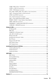
... RGB LED connectors 48 JCORSAIR1: CORSAIR Connector 49 Onboard LEDs...50 EZ Debug LED...50 XMP LED...50 JPWRLED1: LED power input 50 LED_SW1: EZ LED Control 51 Debug Code LED...51 Hexadecimal Character Table 51 Boot Phases...51 Debug Code LED Table 52 ACPI States Codes 56 CPU Temperature 56 Installing OS, Drivers & Utilities 57 Installing Windows® 10 57 Installing Drivers 57 Installing Utilities 57 UEFI BIOS...58 BIOS Setup...59 Entering BIOS Setup 59 Resetting BIOS...60 Updating BIOS...60 EZ Mode...62 Advanced Mode ...65 SETTINGS Menu...66 OC Menu...68 M-FLASH Menu...
... RGB LED connectors 48 JCORSAIR1: CORSAIR Connector 49 Onboard LEDs...50 EZ Debug LED...50 XMP LED...50 JPWRLED1: LED power input 50 LED_SW1: EZ LED Control 51 Debug Code LED...51 Hexadecimal Character Table 51 Boot Phases...51 Debug Code LED Table 52 ACPI States Codes 56 CPU Temperature 56 Installing OS, Drivers & Utilities 57 Installing Windows® 10 57 Installing Drivers 57 Installing Utilities 57 UEFI BIOS...58 BIOS Setup...59 Entering BIOS Setup 59 Resetting BIOS...60 Updating BIOS...60 EZ Mode...62 Advanced Mode ...65 SETTINGS Menu...66 OC Menu...68 M-FLASH Menu...
User Manual
Page 14
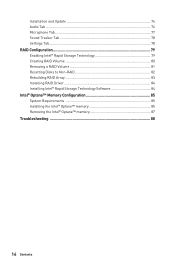
Installation and Update 76 Audio Tab...76 Microphone Tab...77 Sound Tracker Tab 78 Settings Tab...78 RAID Configuration 79 Enabling Intel® Rapid Storage Technology 79 Creating RAID Volume 80 Removing a RAID Volume 81 Resetting Disks to Non-RAID 82 Rebuilding RAID Array 83 Installing RAID Driver 84 Installing Intel® Rapid Storage Technology Software 84 Intel® Optane™ Memory Configuration 85 System Requirements 85 Installing the Intel® Optane™ memory 85 Removing the Intel® Optane™ memory 87 Troubleshooting 88 14 Contents
Installation and Update 76 Audio Tab...76 Microphone Tab...77 Sound Tracker Tab 78 Settings Tab...78 RAID Configuration 79 Enabling Intel® Rapid Storage Technology 79 Creating RAID Volume 80 Removing a RAID Volume 81 Resetting Disks to Non-RAID 82 Rebuilding RAID Array 83 Installing RAID Driver 84 Installing Intel® Rapid Storage Technology Software 84 Intel® Optane™ Memory Configuration 85 System Requirements 85 Installing the Intel® Optane™ memory 85 Removing the Intel® Optane™ memory 87 Troubleshooting 88 14 Contents
User Manual
Page 20
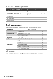
It should contain: Motherboard MEG Z490 UNIFY User manual 1 Documentation Case stand-off notification 1 Quick installation guide 1 Application Driver DVD 1 Cables SATA 6G cables (2 cables/pack) 2 Wi-Fi Antenna 1 Case badge 1 Accessories SATA cable stickers 1 Product registration card 1 M.2 screws (3 pcs./pack) 1 ⚠⚠Important If any of your retailer. 20 Package contents JCORSAIR1 Connector Specification Supporting CORSAIR RGB Products Lighting Node PRO LED Strip HD120 RGB Fan SP120 RGB Fan LL120 RGB Fan Maximum connection 20* * 20% brightness is ...
It should contain: Motherboard MEG Z490 UNIFY User manual 1 Documentation Case stand-off notification 1 Quick installation guide 1 Application Driver DVD 1 Cables SATA 6G cables (2 cables/pack) 2 Wi-Fi Antenna 1 Case badge 1 Accessories SATA cable stickers 1 Product registration card 1 M.2 screws (3 pcs./pack) 1 ⚠⚠Important If any of your retailer. 20 Package contents JCORSAIR1 Connector Specification Supporting CORSAIR RGB Products Lighting Node PRO LED Strip HD120 RGB Fan SP120 RGB Fan LL120 RGB Fan Maximum connection 20* * 20% brightness is ...
User Manual
Page 31
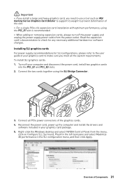
... SLI configurations, please refer to the user guide of the slot. ∙∙For a single PCIe x16 expansion card installation with optimum performance, using the SLI Bridge Connector. 3. Connect the two cards together using the PCI_E1 slot is recommended. ∙∙When adding or removing expansion cards, always turn off your graphics card package. 5. Installing SLI graphics cards For power supply recommendations for any necessary additional hardware or software changes. Right-click the Windows desktop and select NVIDIA Control Panel from the power...
... SLI configurations, please refer to the user guide of the slot. ∙∙For a single PCIe x16 expansion card installation with optimum performance, using the SLI Bridge Connector. 3. Connect the two cards together using the PCI_E1 slot is recommended. ∙∙When adding or removing expansion cards, always turn off your graphics card package. 5. Installing SLI graphics cards For power supply recommendations for any necessary additional hardware or software changes. Right-click the Windows desktop and select NVIDIA Control Panel from the power...
User Manual
Page 48
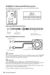
... the power outlet before installing or removing the RGB LED strip. ∙∙Please use MSI's software to control the extended LED strip. 48 Overview of LED strips. JRAINBOW1~2: Addressable RGB LED connectors The JRAINBOW connectors allow you to connect the WS2812B Individually Addressable RGB LED strips 5V. 1 JRAINBOW1~2 1 +5V 2 Data 3 No Pin 4 Ground Addressable RGB LED Strip Connection 1 +5V D JRAINBOW connector Rainbow RGB LED extension cable Addressable RGB LED Fan Connection JRAINBOW connector 1 WS2812B...
... the power outlet before installing or removing the RGB LED strip. ∙∙Please use MSI's software to control the extended LED strip. 48 Overview of LED strips. JRAINBOW1~2: Addressable RGB LED connectors The JRAINBOW connectors allow you to connect the WS2812B Individually Addressable RGB LED strips 5V. 1 JRAINBOW1~2 1 +5V 2 Data 3 No Pin 4 Ground Addressable RGB LED Strip Connection 1 +5V D JRAINBOW connector Rainbow RGB LED extension cable Addressable RGB LED Fan Connection JRAINBOW connector 1 WS2812B...

User Manual
Page 52
... - 3A 3B PEI Core is started Pre-memory CPU initialization is started Pre-memory CPU initialization (CPU module specific) Pre-memory System Agent initialization is started Pre-Memory System Agent initialization (System Agent module specific) Pre-memory PCH initialization is started CPU post-memory initialization. Boot Strap Processor (BSP) selection CPU post-memory initialization. Configuring memory Memory initialization (other) Memory Installed CPU post-memory initialization is started 52 Onboard LEDs Cache initialization CPU post-memory initialization. Debug Code LED Table SEC...
... - 3A 3B PEI Core is started Pre-memory CPU initialization is started Pre-memory CPU initialization (CPU module specific) Pre-memory System Agent initialization is started Pre-Memory System Agent initialization (System Agent module specific) Pre-memory PCH initialization is started CPU post-memory initialization. Boot Strap Processor (BSP) selection CPU post-memory initialization. Configuring memory Memory initialization (other) Memory Installed CPU post-memory initialization is started 52 Onboard LEDs Cache initialization CPU post-memory initialization. Debug Code LED Table SEC...
User Manual
Page 53
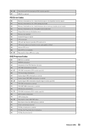
... DXE initialization is started PCH DXE SMM initialization is started PCH devices initialization PCH DXE Initialization (PCH module specific) ACPI module initialization CSM initialization Reserved for future AMI DXE codes Boot Device Selection (BDS) phase is started Driver connecting is started PCI Bus initialization is started PCI Bus Hot Plug Controller Initialization PCI Bus Enumeration 32 Onboard LEDs 53 Invalid memory type or incompatible memory speed Memory initialization error. Invalid memory size or memory modules do not match Memory initialization error. SPD reading has...
... DXE initialization is started PCH DXE SMM initialization is started PCH devices initialization PCH DXE Initialization (PCH module specific) ACPI module initialization CSM initialization Reserved for future AMI DXE codes Boot Device Selection (BDS) phase is started Driver connecting is started PCI Bus initialization is started PCI Bus Hot Plug Controller Initialization PCI Bus Enumeration 32 Onboard LEDs 53 Invalid memory type or incompatible memory speed Memory initialization error. Invalid memory size or memory modules do not match Memory initialization error. SPD reading has...

User Manual
Page 54
...USB initialization is started USB Reset USB Detect USB Enable Reserved for future AMI codes IDE initialization is started IDE Reset IDE Detect IDE Enable SCSI initialization is started SCSI Reset SCSI Detect SCSI Enable Setup Verifying Password Start of Setup Setup Input Wait Ready To Boot event Legacy Boot event Exit Boot Services event Runtime Set Virtual Address MAP Begin Runtime Set Virtual Address MAP End Legacy Option ROM Initialization System Reset USB hot plug PCI bus hot plug Clean-up of NVRAM Configuration Reset (reset of NVRAM settings) Reserved for future AMI codes DXE Error Codes...
...USB initialization is started USB Reset USB Detect USB Enable Reserved for future AMI codes IDE initialization is started IDE Reset IDE Detect IDE Enable SCSI initialization is started SCSI Reset SCSI Detect SCSI Enable Setup Verifying Password Start of Setup Setup Input Wait Ready To Boot event Legacy Boot event Exit Boot Services event Runtime Set Virtual Address MAP Begin Runtime Set Virtual Address MAP End Legacy Option ROM Initialization System Reset USB hot plug PCI bus hot plug Clean-up of NVRAM Configuration Reset (reset of NVRAM settings) Reserved for future AMI codes DXE Error Codes...
User Manual
Page 57
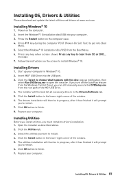
... turn off the AutoPlay feature from the root path of the MSI USB Drive. 4. Click the Install button in the Drivers/Software tab. 5. Installing Utilities Before you install utilities, you can still manually execute the DVDSetup.exe from the Windows Control Panel, you must complete drivers installation. 1. Press F11 key during the computer POST (Power-On Self Test) to boot from the Boot Menu. 6. Press any key when screen shows Press any key to get into the USB port. 3. Start...
... turn off the AutoPlay feature from the root path of the MSI USB Drive. 4. Click the Install button in the Drivers/Software tab. 5. Installing Utilities Before you install utilities, you can still manually execute the DVDSetup.exe from the Windows Control Panel, you must complete drivers installation. 1. Press F11 key during the computer POST (Power-On Self Test) to boot from the Boot Menu. 6. Press any key when screen shows Press any key to get into the USB port. 3. Start...

User Manual
Page 60
... save the BIOS file into the USB port. 2. Press to activate M-Flash for resetting BIOS. Insert the USB flash drive that matches your motherboard model from MSI website. Resetting BIOS You might need to restore the default BIOS setting to solve certain problems. There are several ways to reset BIOS: ∙∙Go to BIOS and press F6 to load optimized defaults. ∙∙Short the Clear CMOS jumper on Yes to start recovering BIOS. 5. Select a BIOS file to perform the BIOS update process...
... save the BIOS file into the USB port. 2. Press to activate M-Flash for resetting BIOS. Insert the USB flash drive that matches your motherboard model from MSI website. Resetting BIOS You might need to restore the default BIOS setting to solve certain problems. There are several ways to reset BIOS: ∙∙Go to BIOS and press F6 to load optimized defaults. ∙∙Short the Clear CMOS jumper on Yes to start recovering BIOS. 5. Select a BIOS file to perform the BIOS update process...
User Manual
Page 61
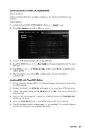
... the Flash BIOS Button to install CPU and memory.) 4. After the flashing process is set properly. Click on Download icon to achieve by reset button. Select the BIOS file and click on Scan button to the root of your motherboard model from the MSI® website. 2. Plug the USB flash drive that matches your USB flash drive. 3. The LED will restart automatically. Connect the power supply to CPU_PWR1 and ATX_PWR1. (No need to flash BIOS, and the LED starts flashing. 6. Rename the BIOS file to MSI.ROM...
... the Flash BIOS Button to install CPU and memory.) 4. After the flashing process is set properly. Click on Download icon to achieve by reset button. Select the BIOS file and click on Scan button to the root of your motherboard model from the MSI® website. 2. Plug the USB flash drive that matches your USB flash drive. 3. The LED will restart automatically. Connect the power supply to CPU_PWR1 and ATX_PWR1. (No need to flash BIOS, and the LED starts flashing. 6. Rename the BIOS file to MSI.ROM...
User Manual
Page 63
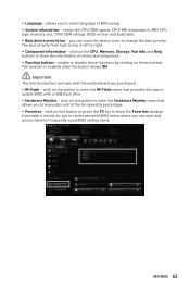
... create personal BIOS menu where you can save and access favorite/ frequently-used BIOS setting items. UEFI BIOS 63 shows the CPU/ DDR speed, CPU/ MB temperature, MB/ CPU type, memory size, CPU/ DDR voltage, BIOS version and build date. ∙∙ Boot device priority bar - ∙∙ Language - click on this button or press the F3 key to show the Favorites window. click on the CPU, Memory, Storage, Fan Info and Help buttons to show the information of BIOS setup. ∙...
... create personal BIOS menu where you can save and access favorite/ frequently-used BIOS setting items. UEFI BIOS 63 shows the CPU/ DDR speed, CPU/ MB temperature, MB/ CPU type, memory size, CPU/ DDR voltage, BIOS version and build date. ∙∙ Boot device priority bar - ∙∙ Language - click on this button or press the F3 key to show the Favorites window. click on the CPU, Memory, Storage, Fan Info and Help buttons to show the information of BIOS setup. ∙...

User Manual
Page 67
... Setup sub-menu Sets system wake up behaviors for different sleep modes. ▶▶Secure Erase+ Enables or disables Secure Erase+ function. Once the password is only available when using the Intel thunderbolt device. ▶▶USB Configuration sub-menu Sets the onboard USB controller and device function. Press Enter to enter the sub-menu. ▶▶Power Management Setup sub-menu Sets system Power Management of system boot devices. ▶▶Security sub-menu Use this menu to set password from a SSD. To clear a set...
... Setup sub-menu Sets system wake up behaviors for different sleep modes. ▶▶Secure Erase+ Enables or disables Secure Erase+ function. Once the password is only available when using the Intel thunderbolt device. ▶▶USB Configuration sub-menu Sets the onboard USB controller and device function. Press Enter to enter the sub-menu. ▶▶Power Management Setup sub-menu Sets system Power Management of system boot devices. ▶▶Security sub-menu Use this menu to set password from a SSD. To clear a set...
User Manual
Page 69
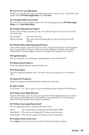
... when the installed CPU supports this setting automatically. Read-only. ▶▶GT Ratio [Auto] Sets the integrated graphics ratio. This item appears when a CPU that overclocking behavior and stability is installed. ▶▶CPU Base Clock Apply Mode [Auto]* Sets the applying mode for heat dissipation when running AVX instructions. This item only appears when CPU Ratio Apply Mode set to CPU features. ▶▶CPU Base Clock (MHz) [Default] Sets the CPU Base clock. key to...
... when the installed CPU supports this setting automatically. Read-only. ▶▶GT Ratio [Auto] Sets the integrated graphics ratio. This item appears when a CPU that overclocking behavior and stability is installed. ▶▶CPU Base Clock Apply Mode [Auto]* Sets the applying mode for heat dissipation when running AVX instructions. This item only appears when CPU Ratio Apply Mode set to CPU features. ▶▶CPU Base Clock (MHz) [Default] Sets the CPU Base clock. key to...

User Manual
Page 70
... CPU Core/ GT voltage mode. 70 UEFI BIOS The valid value range depends on the installed CPU. Please note the overclocking behavior is installed. ▶▶DRAM Frequency [Auto] Sets the DRAM frequency. The system may become unstable or unbootable after changing memory timing. If it occurs, please clear the CMOS data and restore the default settings. (Refer to the Clear CMOS jumper/ button section to clear the CMOS data, and enter the BIOS to load the default settings.) ▶▶Memory Fast Boot [Auto] * Enables or disables...
... CPU Core/ GT voltage mode. 70 UEFI BIOS The valid value range depends on the installed CPU. Please note the overclocking behavior is installed. ▶▶DRAM Frequency [Auto] Sets the DRAM frequency. The system may become unstable or unbootable after changing memory timing. If it occurs, please clear the CMOS data and restore the default settings. (Refer to the Clear CMOS jumper/ button section to clear the CMOS data, and enter the BIOS to load the default settings.) ▶▶Memory Fast Boot [Auto] * Enables or disables...
User Manual
Page 76
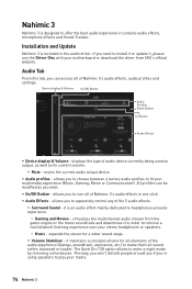
... audio experience it in the audio driver. Audio Tab From this tab, you to retrieve a multichannel listening experience over your media. 76 Nahimic 3 displays the type of Nahimic 3's audio effects, audio profiles and settings. Nahimic 3 Nahimic 3 is designed to enter a night mode by removing some basses. allows you can be modified as its current volume. ▪▪Mute - virtualizes the multichannel audio stream from MSI...
... audio experience it in the audio driver. Audio Tab From this tab, you to retrieve a multichannel listening experience over your media. 76 Nahimic 3 displays the type of Nahimic 3's audio effects, audio profiles and settings. Nahimic 3 Nahimic 3 is designed to enter a night mode by removing some basses. allows you can be modified as its current volume. ▪▪Mute - virtualizes the multichannel audio stream from MSI...
User Manual
Page 84
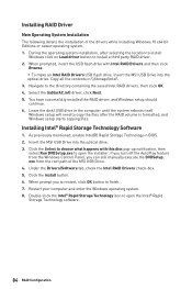
... an Intel RAID Drivers USB flash drive. If you turn off the AutoPlay feature from the root path of the drivers while installing Windows 10 x64 bit Editions or newer operating system. 1. Click the Install button. 6. Restart your computer and enter the Windows operating system. 8. Insert the MSI USB Drive into the optical drive. 3. Insert the MSI USB Drive into the optical drive. Installing Intel® Rapid Storage Technology Software 1. When prompt you can still manually execute...
... an Intel RAID Drivers USB flash drive. If you turn off the AutoPlay feature from the root path of the drivers while installing Windows 10 x64 bit Editions or newer operating system. 1. Click the Install button. 6. Restart your computer and enter the Windows operating system. 8. Insert the MSI USB Drive into the optical drive. 3. Insert the MSI USB Drive into the optical drive. Installing Intel® Rapid Storage Technology Software 1. When prompt you can still manually execute...
User Manual
Page 85
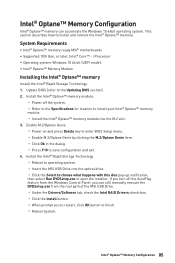
...® Optane™ memory ready MSI® motherboards ∙∙Supported 10th Gen, or later, Intel® Core™ - i Processor ∙∙Operating system: Windows 10 64 bit (UEFI mode). ∙∙Intel® Optane™ Memory Module Installing the Intel® Optane™ memory Install the Intel® Rapid Storage Technology. 1. Enable M.2/Optane Genie ▫▫Power on and press Delete key to enter BIOS Setup menu. ▫▫Enable M.2/Optane Genie by...
...® Optane™ memory ready MSI® motherboards ∙∙Supported 10th Gen, or later, Intel® Core™ - i Processor ∙∙Operating system: Windows 10 64 bit (UEFI mode). ∙∙Intel® Optane™ Memory Module Installing the Intel® Optane™ memory Install the Intel® Rapid Storage Technology. 1. Enable M.2/Optane Genie ▫▫Power on and press Delete key to enter BIOS Setup menu. ▫▫Enable M.2/Optane Genie by...
User Manual
Page 88
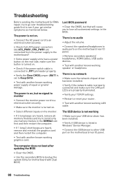
... working speaker or headphone. There is no network ∙∙Make sure the network chipset driver has been installed. ∙∙Verify if the network cable is properly connected and make sure the LAN port LEDs are connected from the power supply to the motherboard? ∙∙Some power supply units have a power button on the rear side, make sure the button is turned on. ∙∙Check if the power switch cable is connected to JFP1 pin header...
... working speaker or headphone. There is no network ∙∙Make sure the network chipset driver has been installed. ∙∙Verify if the network cable is properly connected and make sure the LAN port LEDs are connected from the power supply to the motherboard? ∙∙Some power supply units have a power button on the rear side, make sure the button is turned on. ∙∙Check if the power switch cable is connected to JFP1 pin header...


