User Manual
Page 1
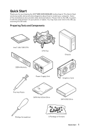
.... Some of Screws Quick Start 1 You may have even link to the URL by scanning the QR code. Quick Start Thank you for purchasing the MSI® MEG Z490 GODLIKE motherboard.
.... Some of Screws Quick Start 1 You may have even link to the URL by scanning the QR code. Quick Start Thank you for purchasing the MSI® MEG Z490 GODLIKE motherboard.

User Manual
Page 2
... you can not step on it may cause the computer to not recognize a component or fail to start. ∙∙Hold the motherboard by the edges to avoid touching sensitive components. ∙∙It is recommended to wear an electrostatic discharge (ESD) wrist strap when handling...any of static electricity by service personnel: ▪▪Liquid has penetrated into the computer. ▪▪The motherboard has been exposed to moisture. ▪▪The motherboard does not work according to prevent electrostatic damage. This could cause permanent damage to the components as well as ...
... you can not step on it may cause the computer to not recognize a component or fail to start. ∙∙Hold the motherboard by the edges to avoid touching sensitive components. ∙∙It is recommended to wear an electrostatic discharge (ESD) wrist strap when handling...any of static electricity by service personnel: ▪▪Liquid has penetrated into the computer. ▪▪The motherboard has been exposed to moisture. ▪▪The motherboard does not work according to prevent electrostatic damage. This could cause permanent damage to the components as well as ...

User Manual
Page 6
Installing the Motherboard 1 Torque: 3 kgf·cm* 2 *3 kgf·cm = 0.3 N·m = 2.6 lbf·in 6 Quick Start
Installing the Motherboard 1 Torque: 3 kgf·cm* 2 *3 kgf·cm = 0.3 N·m = 2.6 lbf·in 6 Quick Start

User Manual
Page 12
Contents Quick Start ...1 Preparing Tools and Components 1 Safety Information 2 Installing a Processor 3 Installing DDR4 memory 4 Connecting the Front Panel Header 5 Installing the Motherboard 6 Connecting the Power Connectors 7 Installing SATA Drives 8 Installing a Graphics Card 9 Connecting Peripheral Devices 10 Power On...11 Specifications...15 JCORSAIR1 Connector Specification 22 Package contents ...
Contents Quick Start ...1 Preparing Tools and Components 1 Safety Information 2 Installing a Processor 3 Installing DDR4 memory 4 Connecting the Front Panel Header 5 Installing the Motherboard 6 Connecting the Power Connectors 7 Installing SATA Drives 8 Installing a Graphics Card 9 Connecting Peripheral Devices 10 Power On...11 Specifications...15 JCORSAIR1 Connector Specification 22 Package contents ...
User Manual
Page 23
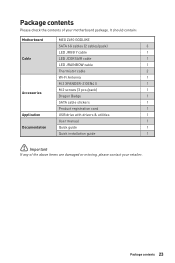
Package contents Please check the contents of the above items are damaged or missing, please contact your motherboard package. Package contents 23 It should contain: Motherboard MEG Z490 GODLIKE SATA 6G cables (2 cables/pack) 3 LED JRGB Y cable 1 Cable LED JCORSAIR cable 1 LED JRAINBOW cable 1 Thermistor cable 2 Wi-Fi Antenna 1 M.2 XPANDER-Z GEN4 S 1 M.2 screws (3 pcs./pack) 1 ...
Package contents Please check the contents of the above items are damaged or missing, please contact your motherboard package. Package contents 23 It should contain: Motherboard MEG Z490 GODLIKE SATA 6G cables (2 cables/pack) 3 LED JRGB Y cable 1 Cable LED JCORSAIR cable 1 LED JRAINBOW cable 1 Thermistor cable 2 Wi-Fi Antenna 1 M.2 XPANDER-Z GEN4 S 1 M.2 screws (3 pcs./pack) 1 ...
User Manual
Page 31
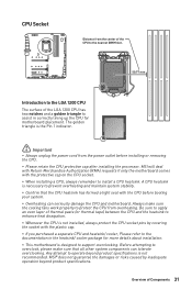
..., Please refer to the documentation in correctly lining up the CPU for more details about installation. ∙∙This motherboard is necessary to prevent overheating and maintain system stability. ∙∙Confirm that all other system components can seriously damage the CPU... a CPU, always remember to install a CPU heatsink. A CPU heatsink is designed to support overclocking. MSI will deal with Return Merchandise Authorization (RMA) requests if only the motherboard comes with the CPU before installing or removing the CPU. ∙∙Please retain the CPU protective cap...
..., Please refer to the documentation in correctly lining up the CPU for more details about installation. ∙∙This motherboard is necessary to prevent overheating and maintain system stability. ∙∙Confirm that all other system components can seriously damage the CPU... a CPU, always remember to install a CPU heatsink. A CPU heatsink is designed to support overclocking. MSI will deal with Return Merchandise Authorization (RMA) requests if only the motherboard comes with the CPU before installing or removing the CPU. ∙∙Please retain the CPU protective cap...

User Manual
Page 38
... supplied JSMB cable to secure the card. 10 9 PCI_E2 11. Use a screw to connect the JSMB connector on the card and JSMB1 connector on the motherboard. Insert the card into the PCI_E2 slot. 10. 9. Using the supplied HDD LED cable to connect the JMB connector and JFP1's HDD pins (pin 1 & pin3...
... supplied JSMB cable to secure the card. 10 9 PCI_E2 11. Use a screw to connect the JSMB connector on the card and JSMB1 connector on the motherboard. Insert the card into the PCI_E2 slot. 10. 9. Using the supplied HDD LED cable to connect the JMB connector and JFP1's HDD pins (pin 1 & pin3...

User Manual
Page 40
... flat connector be connected to one SATA device. SATA1~6: SATA 6Gb/s Connectors These connectors are SATA 6Gb/s interface ports. Each connector can connect to the motherboard for space saving purposes. ∙∙SATA2 will be unavailable when installing M.2 SATA SSD in the M2_1 slot. ∙∙SATA5 & SATA6 will be unavailable...
... flat connector be connected to one SATA device. SATA1~6: SATA 6Gb/s Connectors These connectors are SATA 6Gb/s interface ports. Each connector can connect to the motherboard for space saving purposes. ∙∙SATA2 will be unavailable when installing M.2 SATA SSD in the M2_1 slot. ∙∙SATA5 & SATA6 will be unavailable...

User Manual
Page 41
Overview of the motherboard. CPU_PWR1~2, ATX_PWR1, PCIE_PWR1: Power Connectors These connectors allow you to connect an ATX power supply. 8 5 CPU_PWR1~2 4 1 1 Ground 5 2 Ground 6 3 Ground 7 4 Ground 8 +12V +12V +12V +12V 1 +3.3V ...
Overview of the motherboard. CPU_PWR1~2, ATX_PWR1, PCIE_PWR1: Power Connectors These connectors allow you to connect an ATX power supply. 8 5 CPU_PWR1~2 4 1 1 Ground 5 2 Ground 6 3 Ground 7 4 Ground 8 +12V +12V +12V +12V 1 +3.3V ...

User Manual
Page 49
.... 2. Keep Data (default) Clear CMOS/ Reset BIOS Resetting BIOS to short JBAT1 for about 5-10 seconds. 3. Remove the jumper cap from a battery located on the motherboard to save system configuration data. If you to clear the CMOS memory. POWER1, RESET1: Power Button, Reset Button The Power / Reset button allows you want...
.... 2. Keep Data (default) Clear CMOS/ Reset BIOS Resetting BIOS to short JBAT1 for about 5-10 seconds. 3. Remove the jumper cap from a battery located on the motherboard to save system configuration data. If you to clear the CMOS memory. POWER1, RESET1: Power Button, Reset Button The Power / Reset button allows you want...

User Manual
Page 50
...Multi-BIOS switch. 3. Power on Yes to enter BIOS setup during POST. 5. Before recovering, please download the latest BIOS file that matches your motherboard model from MSI website. Insert the USB flash drive into the computer. 4. Select the M-FLASH tab and click on the computer and press Del key to reboot... the flash mode. 6. Select a BIOS file to the other for details. 50 Overview of the USB flash drive. 1. BIOS_SW1: Multi-BIOS Switch This motherboard has two built-in BIOS ROMs. If one is booting up. ∙∙You can also use the Multi-BIOS switch when system is crashed...
...Multi-BIOS switch. 3. Power on Yes to enter BIOS setup during POST. 5. Before recovering, please download the latest BIOS file that matches your motherboard model from MSI website. Insert the USB flash drive into the computer. 4. Select the M-FLASH tab and click on the computer and press Del key to reboot... the flash mode. 6. Select a BIOS file to the other for details. 50 Overview of the USB flash drive. 1. BIOS_SW1: Multi-BIOS Switch This motherboard has two built-in BIOS ROMs. If one is booting up. ∙∙You can also use the Multi-BIOS switch when system is crashed...

User Manual
Page 53
...9888;⚠Important JCORSAIR1 connector ∙∙Fans must start at the same time. Once all items are connected properly, you to the motherboard specification. ∙∙CORSAIR RGB LED Fan and CORSAIR Lighting Node PRO can control the CORSAIR RGB LED strips and fans with the... CORSAIR fan hub. Please refer to connect the CORSAIR Individually Addressable Lighting PRO RGB LED strips 5V or CORSAIR RGB fans with MSI's software. Overview of RGB LED Fans or RGB LED Lighting PRO strips supported may differ between models. JCORSAIR1: CORSAIR Connector The JCORSAIR1...
...9888;⚠Important JCORSAIR1 connector ∙∙Fans must start at the same time. Once all items are connected properly, you to the motherboard specification. ∙∙CORSAIR RGB LED Fan and CORSAIR Lighting Node PRO can control the CORSAIR RGB LED strips and fans with the... CORSAIR fan hub. Please refer to connect the CORSAIR Individually Addressable Lighting PRO RGB LED strips 5V or CORSAIR RGB fans with MSI's software. Overview of RGB LED Fans or RGB LED Lighting PRO strips supported may differ between models. JCORSAIR1: CORSAIR Connector The JCORSAIR1...

User Manual
Page 55
Onboard LEDs EZ Debug LED These LEDs indicate the debug status of the motherboard. CPU - DRAM - BOOT - XMP LED JPWRLED1: LED power input This connector is not detected or fail. indicates CPU is used by retailers to demonstrate onboard LED lights. indicates DRAM is not detected or fail. indicates the booting device is not detected or fail. JPWRLED1 - VGA - XMP LED This LED indicates the XMP (Extreme Memory Profile) mode is not detected or fail. LED power input Onboard LEDs 55 indicates GPU is enabled.
Onboard LEDs EZ Debug LED These LEDs indicate the debug status of the motherboard. CPU - DRAM - BOOT - XMP LED JPWRLED1: LED power input This connector is not detected or fail. indicates CPU is used by retailers to demonstrate onboard LED lights. indicates DRAM is not detected or fail. indicates the booting device is not detected or fail. JPWRLED1 - VGA - XMP LED This LED indicates the XMP (Extreme Memory Profile) mode is not detected or fail. LED power input Onboard LEDs 55 indicates GPU is enabled.

User Manual
Page 57
... to the Debug Code LED table for details. initial low-level initialization Pre-EFI Initialization (PEI) - Refer to switch on/ off all the LEDs of motherboard. Debug Code LED Hexadecimal Character Table Hexadecimal 0 1 2 3 4 5 6 7 8 9 A B C D E F Debug Code LED display 0123456789ABCDEF Boot Phases Security (SEC) - system setup, pre-OS user interface & selecting a bootable device...
... to the Debug Code LED table for details. initial low-level initialization Pre-EFI Initialization (PEI) - Refer to switch on/ off all the LEDs of motherboard. Debug Code LED Hexadecimal Character Table Hexadecimal 0 1 2 3 4 5 6 7 8 9 A B C D E F Debug Code LED display 0123456789ABCDEF Boot Phases Security (SEC) - system setup, pre-OS user interface & selecting a bootable device...

User Manual
Page 64
...GUID Partition Table (GPT). ∙∙Supports unlimited number of partitions. ∙∙Supports full capabilities of the new chipset's capabilities. this motherboard supports only Windows 10 64-bit operating system. ∙∙ Older graphics card - That allows you to use a GOP/ UEFI compatible ...: VCore: DDR Voltage: BIOS Mode: UEFI/CSM UEFI boot mode CPU Temperature: Motherboard Temperature: VCore: DDR Voltage: BIOS Mode: UEFI/CSM CSM boot mode 64 UEFI BIOS UEFI BIOS MSI UEFI BIOS is no malware tampers with UEFI compatible devices during POST. ∙∙Supports...
...GUID Partition Table (GPT). ∙∙Supports unlimited number of partitions. ∙∙Supports full capabilities of the new chipset's capabilities. this motherboard supports only Windows 10 64-bit operating system. ∙∙ Older graphics card - That allows you to use a GOP/ UEFI compatible ...: VCore: DDR Voltage: BIOS Mode: UEFI/CSM UEFI boot mode CPU Temperature: Motherboard Temperature: VCore: DDR Voltage: BIOS Mode: UEFI/CSM CSM boot mode 64 UEFI BIOS UEFI BIOS MSI UEFI BIOS is no malware tampers with UEFI compatible devices during POST. ∙∙Supports...

User Manual
Page 66
...: Please download the latest BIOS file that contains the update file into the USB flash drive. Insert the USB flash drive that matches your motherboard model from MSI website. Updating BIOS: 1. And then save the BIOS file into the USB port. 2. Please refer to the Clear CMOS jumper/ button section ... ways to reset BIOS: ∙∙Go to BIOS and press F6 to load optimized defaults. ∙∙Short the Clear CMOS jumper on the motherboard. ∙∙Press the Clear CMOS button on the rear I/O panel. ⚠⚠Important Be sure the computer is 100% completed, the system ...
...: Please download the latest BIOS file that contains the update file into the USB flash drive. Insert the USB flash drive that matches your motherboard model from MSI website. Updating BIOS: 1. And then save the BIOS file into the USB port. 2. Please refer to the Clear CMOS jumper/ button section ... ways to reset BIOS: ∙∙Go to BIOS and press F6 to load optimized defaults. ∙∙Short the Clear CMOS jumper on the motherboard. ∙∙Press the Clear CMOS button on the rear I/O panel. ⚠⚠Important Be sure the computer is 100% completed, the system ...
User Manual
Page 67
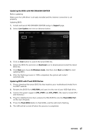
... search the latest BIOS file. 4. Plug the USB flash drive that matches your USB flash drive. 3. Updating BIOS: 1. Updating BIOS with MSI DRAGON CENTER Before updating: Make sure the LAN driver is already installed and the internet connection is completed. The LED will restart automatically. Please download... Live Update and click on the rear I/O panel. 5. Select the BIOS file and click on Scan button to the root of your motherboard model from the MSI® website. 2. UEFI BIOS 67 And then click Next and Start to download and install the latest BIOS file. 5. Install and ...
... search the latest BIOS file. 4. Plug the USB flash drive that matches your USB flash drive. 3. Updating BIOS: 1. Updating BIOS with MSI DRAGON CENTER Before updating: Make sure the LAN driver is already installed and the internet connection is completed. The LED will restart automatically. Please download... Live Update and click on the rear I/O panel. 5. Select the BIOS file and click on Scan button to the root of your motherboard model from the MSI® website. 2. UEFI BIOS 67 And then click Next and Start to download and install the latest BIOS file. 5. Install and ...

User Manual
Page 68
... switch - To configure the advanced BIOS settings, please enter the Advanced Mode by BIOS item name. This function is only available when both of the motherboard and CPU are available. 68 UEFI BIOS click on this tab or the F7 key to configure the basic setting.
... switch - To configure the advanced BIOS settings, please enter the Advanced Mode by BIOS item name. This function is only available when both of the motherboard and CPU are available. 68 UEFI BIOS click on this tab or the F7 key to configure the basic setting.

User Manual
Page 69
... reset button to select language of connected component. ∙∙ Function buttons - allows you to reboot the system and the system will vary with the motherboard you can move the device icons to be forced into BIOS with the previous BIOS settings. ▪▪Turbo Fan - ∙∙ Smart Button - Click...
... reset button to select language of connected component. ∙∙ Function buttons - allows you to reboot the system and the system will vary with the motherboard you can move the device icons to be forced into BIOS with the previous BIOS settings. ▪▪Turbo Fan - ∙∙ Smart Button - Click...

User Manual
Page 72
... you to manage overclocking profiles. ▪▪HARDWARE MONITOR - allows you to set the speeds of fans and monitor voltages of installed devices on this motherboard. ∙∙ Menu display -
... you to manage overclocking profiles. ▪▪HARDWARE MONITOR - allows you to set the speeds of fans and monitor voltages of installed devices on this motherboard. ∙∙ Menu display -


