
User Manual
Page 12
... a Processor 3 Installing DDR4 memory 4 Connecting the Front Panel Header 5 Installing the Motherboard 6 Connecting the Power Connectors 7 Installing SATA Drives 8 Installing a Graphics Card 9 Connecting Peripheral Devices 10 Power On...11 Specifications...15 JCORSAIR1 Connector Specification 22 Package contents 23 Block Diagram ...24 Rear I/O Panel ...25 LAN Port LED Status Table 25 Audio Ports Configuration 25 Realtek Audio Console 26 Installing Antennas 28 Overview of Components 29 CPU Socket ...31 DIMM Slots...32 PCI_E1~4: PCIe Expansion Slots 33 M2_1~3: M.2 Slots (Key...
... a Processor 3 Installing DDR4 memory 4 Connecting the Front Panel Header 5 Installing the Motherboard 6 Connecting the Power Connectors 7 Installing SATA Drives 8 Installing a Graphics Card 9 Connecting Peripheral Devices 10 Power On...11 Specifications...15 JCORSAIR1 Connector Specification 22 Package contents 23 Block Diagram ...24 Rear I/O Panel ...25 LAN Port LED Status Table 25 Audio Ports Configuration 25 Realtek Audio Console 26 Installing Antennas 28 Overview of Components 29 CPU Socket ...31 DIMM Slots...32 PCI_E1~4: PCIe Expansion Slots 33 M2_1~3: M.2 Slots (Key...

User Manual
Page 13
... Status Table 54 Onboard LEDs ...55 EZ Debug LED...55 XMP LED ...55 JPWRLED1: LED power input 55 CPU Power LED ...56 LED_SW1: EZ LED Control 57 Debug Code LED 57 Hexadecimal Character Table 57 Boot Phases...57 Debug Code LED Table 58 ACPI States Codes 62 CPU core /CPU socket / System / MOS / PCH Temperature 62 Installing OS, Drivers & Utilities 63 Installing Windows® 10 63 Installing Drivers 63 Installing Utilities 63 UEFI BIOS...64 BIOS Setup...65 Entering BIOS Setup 65 Resetting BIOS...66 Updating BIOS...66 EZ Mode ...68 Advanced Mode ...72 Contents...
... Status Table 54 Onboard LEDs ...55 EZ Debug LED...55 XMP LED ...55 JPWRLED1: LED power input 55 CPU Power LED ...56 LED_SW1: EZ LED Control 57 Debug Code LED 57 Hexadecimal Character Table 57 Boot Phases...57 Debug Code LED Table 58 ACPI States Codes 62 CPU core /CPU socket / System / MOS / PCH Temperature 62 Installing OS, Drivers & Utilities 63 Installing Windows® 10 63 Installing Drivers 63 Installing Utilities 63 UEFI BIOS...64 BIOS Setup...65 Entering BIOS Setup 65 Resetting BIOS...66 Updating BIOS...66 EZ Mode ...68 Advanced Mode ...72 Contents...
User Manual
Page 14
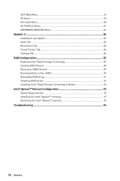
SETTINGS Menu 73 OC Menu...75 M-FLASH Menu ...80 OC PROFILE Menu 81 HARDWARE MONITOR Menu 82 Nahimic 3 ...84 Installation and Update 84 Audio Tab ...84 Microphone Tab ...85 Sound Tracker Tab 86 Settings Tab ...86 RAID Configuration 87 Enabling Intel® Rapid Storage Technology 87 Creating RAID Volume 88 Removing a RAID Volume 89 Resetting Disks to Non-RAID 90 Rebuilding RAID Array 91 Installing RAID Driver 92 Installing Intel® Rapid Storage Technology Software 92 Intel® Optane™ Memory Configuration 93 System Requirements...
SETTINGS Menu 73 OC Menu...75 M-FLASH Menu ...80 OC PROFILE Menu 81 HARDWARE MONITOR Menu 82 Nahimic 3 ...84 Installation and Update 84 Audio Tab ...84 Microphone Tab ...85 Sound Tracker Tab 86 Settings Tab ...86 RAID Configuration 87 Enabling Intel® Rapid Storage Technology 87 Creating RAID Volume 88 Removing a RAID Volume 89 Resetting Disks to Non-RAID 90 Rebuilding RAID Array 91 Installing RAID Driver 92 Installing Intel® Rapid Storage Technology Software 92 Intel® Optane™ Memory Configuration 93 System Requirements...

User Manual
Page 33
... adding or removing expansion cards, always turn off the power supply and unplug the power supply power cable from the power outlet. Read the expansion card's documentation to operate PCIe 3.0 x4 speed. PCIe bandwidth configuration table for any necessary additional hardware or software changes. Overview of the slot. ∙∙For a single PCIe x16 expansion card installation with PCIE x4 card and M2_3 in BIOS for installed M.2 device to check for PCIe & M.2 slots Slot Single 2-Way 3-Way* PCI_E1 (CPU) @ 3.0 x16...
... adding or removing expansion cards, always turn off the power supply and unplug the power supply power cable from the power outlet. Read the expansion card's documentation to operate PCIe 3.0 x4 speed. PCIe bandwidth configuration table for any necessary additional hardware or software changes. Overview of the slot. ∙∙For a single PCIe x16 expansion card installation with PCIE x4 card and M2_3 in BIOS for installed M.2 device to check for PCIe & M.2 slots Slot Single 2-Way 3-Way* PCI_E1 (CPU) @ 3.0 x16...

User Manual
Page 52
... the power outlet before installing or removing the RGB LED strip. ∙∙Please use MSI's software to control the extended LED strip. 52 Overview of LED strips. JRAINBOW1~2: Addressable RGB LED connectors The JRAINBOW connectors allow you to connect the WS2812B Individually Addressable RGB LED strips 5V. 1 JRAINBOW1 1 +5V 3 No Pin 1 JRAINBOW2 2 Data 4 Ground Addressable RGB LED Strip Connection 1 +5V D JRAINBOW connector Rainbow RGB LED extension cable Addressable RGB LED Fan Connection JRAINBOW connector...
... the power outlet before installing or removing the RGB LED strip. ∙∙Please use MSI's software to control the extended LED strip. 52 Overview of LED strips. JRAINBOW1~2: Addressable RGB LED connectors The JRAINBOW connectors allow you to connect the WS2812B Individually Addressable RGB LED strips 5V. 1 JRAINBOW1 1 +5V 3 No Pin 1 JRAINBOW2 2 Data 4 Ground Addressable RGB LED Strip Connection 1 +5V D JRAINBOW connector Rainbow RGB LED extension cable Addressable RGB LED Fan Connection JRAINBOW connector...

User Manual
Page 58
...initialization is started Pre-Memory System Agent initialization (System Agent module specific) Pre-memory PCH initialization is started CPU post-memory initialization. Programming memory timing information Memory initialization. Cache initialization CPU post-memory initialization. Memory presence detection Memory initialization. Configuring memory Memory initialization (other) Memory Installed CPU post-memory initialization is started 58 Onboard LEDs Serial Presence Detect (SPD) data reading Memory initialization. Boot Strap Processor (BSP) selection CPU post-memory initialization...
...initialization is started Pre-Memory System Agent initialization (System Agent module specific) Pre-memory PCH initialization is started CPU post-memory initialization. Programming memory timing information Memory initialization. Cache initialization CPU post-memory initialization. Memory presence detection Memory initialization. Configuring memory Memory initialization (other) Memory Installed CPU post-memory initialization is started 58 Onboard LEDs Serial Presence Detect (SPD) data reading Memory initialization. Boot Strap Processor (BSP) selection CPU post-memory initialization...
User Manual
Page 59
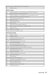
... module specific) PCH DXE initialization is started PCH DXE SMM initialization is started PCH devices initialization PCH DXE Initialization (PCH module specific) ACPI module initialization CSM initialization Reserved for future AMI DXE codes Boot Device Selection (BDS) phase is started Driver connecting is started PCI Bus initialization is started PCI Bus Hot Plug Controller Initialization PCI Bus Enumeration 32 Onboard LEDs 59 Invalid memory type or incompatible memory speed Memory initialization error. Invalid memory size or memory modules do not match Memory initialization error.
... module specific) PCH DXE initialization is started PCH DXE SMM initialization is started PCH devices initialization PCH DXE Initialization (PCH module specific) ACPI module initialization CSM initialization Reserved for future AMI DXE codes Boot Device Selection (BDS) phase is started Driver connecting is started PCI Bus initialization is started PCI Bus Hot Plug Controller Initialization PCI Bus Enumeration 32 Onboard LEDs 59 Invalid memory type or incompatible memory speed Memory initialization error. Invalid memory size or memory modules do not match Memory initialization error.
User Manual
Page 60
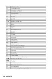
...USB initialization is started USB Reset USB Detect USB Enable Reserved for future AMI codes IDE initialization is started IDE Reset IDE Detect IDE Enable SCSI initialization is started SCSI Reset SCSI Detect SCSI Enable Setup Verifying Password Start of Setup Setup Input Wait Ready To Boot event Legacy Boot event Exit Boot Services event Runtime Set Virtual Address MAP Begin Runtime Set Virtual Address MAP End Legacy Option ROM Initialization System Reset USB hot plug PCI bus hot plug Clean-up of NVRAM Configuration Reset (reset of NVRAM settings) Reserved for future AMI codes DXE Error Codes...
...USB initialization is started USB Reset USB Detect USB Enable Reserved for future AMI codes IDE initialization is started IDE Reset IDE Detect IDE Enable SCSI initialization is started SCSI Reset SCSI Detect SCSI Enable Setup Verifying Password Start of Setup Setup Input Wait Ready To Boot event Legacy Boot event Exit Boot Services event Runtime Set Virtual Address MAP Begin Runtime Set Virtual Address MAP End Legacy Option ROM Initialization System Reset USB hot plug PCI bus hot plug Clean-up of NVRAM Configuration Reset (reset of NVRAM settings) Reserved for future AMI codes DXE Error Codes...
User Manual
Page 63
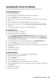
... computer POST (Power-On Self Test) to open the installer. Insert MSI® USB Drive into Boot Menu. 5. Click the Select to choose what happens with this disc pop-up your computer. Click the Install button in Windows® 10. 2. Click OK button to boot from the Windows Control Panel, you must complete drivers installation. 1. Installing OS, Drivers & Utilities 63 Insert the Windows® 10 installation disc/USB into your computer. message. 7. If you turn...
... computer POST (Power-On Self Test) to open the installer. Insert MSI® USB Drive into Boot Menu. 5. Click the Select to choose what happens with this disc pop-up your computer. Click the Install button in Windows® 10. 2. Click OK button to boot from the Windows Control Panel, you must complete drivers installation. 1. Installing OS, Drivers & Utilities 63 Insert the Windows® 10 installation disc/USB into your computer. message. 7. If you turn...

User Manual
Page 66
... to the target BIOS ROM with M-FLASH Before updating: Please download the latest BIOS file that contains the update file into the USB flash drive. Resetting BIOS You might need to restore the default BIOS setting to solve certain problems. There are several ways to reset BIOS: ∙∙Go to BIOS and press F6 to load optimized defaults. ∙∙Short the Clear CMOS jumper on the motherboard. ∙∙Press the Clear CMOS button on the rear I/O panel. ⚠⚠...
... to the target BIOS ROM with M-FLASH Before updating: Please download the latest BIOS file that contains the update file into the USB flash drive. Resetting BIOS You might need to restore the default BIOS setting to solve certain problems. There are several ways to reset BIOS: ∙∙Go to BIOS and press F6 to load optimized defaults. ∙∙Short the Clear CMOS jumper on the motherboard. ∙∙Press the Clear CMOS button on the rear I/O panel. ⚠⚠...
User Manual
Page 67
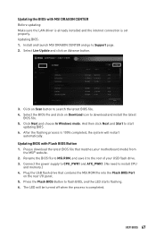
... the LAN driver is already installed and the internet connection is set properly. Please download the latest BIOS file that contains the MSI.ROM file into the Flash BIOS Port on Download icon to search the latest BIOS file. 4. Connect the power supply to CPU_PWR1 and ATX_PWR1. (No need to Support page. 2. Press the Flash BIOS Button to start updating BIOS. 6. Click Next and choose In Windows mode. Rename the BIOS file to MSI.ROM, and save it to the root of your motherboard model...
... the LAN driver is already installed and the internet connection is set properly. Please download the latest BIOS file that contains the MSI.ROM file into the Flash BIOS Port on Download icon to search the latest BIOS file. 4. Connect the power supply to CPU_PWR1 and ATX_PWR1. (No need to Support page. 2. Press the Flash BIOS Button to start updating BIOS. 6. Click Next and choose In Windows mode. Rename the BIOS file to MSI.ROM, and save it to the root of your motherboard model...

User Manual
Page 69
... onboard LEDs. ⚠⚠Important The Mystic Light on the CPU, Memory, Storage, Fan Info and Help buttons to reset the system. ▪▪Mystic Light on these buttons. Click on / off all fans to select language of connected component. ∙∙ Function buttons - shows the CPU/ DDR speed, CPU/ MB temperature, MB/ CPU type, memory size, CPU/ DDR voltage, BIOS version and build date. ∙∙ Boot device priority bar - you to operate full speed or default speeds. ▪▪Configuring Smart Button...
... onboard LEDs. ⚠⚠Important The Mystic Light on the CPU, Memory, Storage, Fan Info and Help buttons to reset the system. ▪▪Mystic Light on these buttons. Click on / off all fans to select language of connected component. ∙∙ Function buttons - shows the CPU/ DDR speed, CPU/ MB temperature, MB/ CPU type, memory size, CPU/ DDR voltage, BIOS version and build date. ∙∙ Boot device priority bar - you to operate full speed or default speeds. ▪▪Configuring Smart Button...

User Manual
Page 73
... SATA/ M.2 cable and power cable connections of the device and motherboard. ▶▶System Information Shows detailed system information, including CPU type, BIOS version, and Memory (read only). ▶▶DMI Information Shows system information, desktop Board Information and chassis Information. (Read only). ▶▶Advanced sub-menu The Advanced sub-menu allows you to set the parameters and behaviors of PCIe, ACPI, integrated peripherals, integrated graphics, USB, power management and Windows . ▶▶PCIe/ PCI...
... SATA/ M.2 cable and power cable connections of the device and motherboard. ▶▶System Information Shows detailed system information, including CPU type, BIOS version, and Memory (read only). ▶▶DMI Information Shows system information, desktop Board Information and chassis Information. (Read only). ▶▶Advanced sub-menu The Advanced sub-menu allows you to set the parameters and behaviors of PCIe, ACPI, integrated peripherals, integrated graphics, USB, power management and Windows . ▶▶PCIe/ PCI...

User Manual
Page 74
... / User Password items, a password box will confirm the password is only available when using the CPU which integrate with or without changes. 74 UEFI BIOS Once the password is only supported with NVMe 1.3 compatible (and above) SSD devices. ▶▶M.2 XPANDER-Z GEN-4 Fan Control Use this sub-menu to set the fan duty cycle and the LED color of the card. ▶▶Boot sub-menu Use this menu to enter a new password. You can enter the setup and...
... / User Password items, a password box will confirm the password is only available when using the CPU which integrate with or without changes. 74 UEFI BIOS Once the password is only supported with NVMe 1.3 compatible (and above) SSD devices. ▶▶M.2 XPANDER-Z GEN-4 Fan Control Use this sub-menu to set the fan duty cycle and the LED color of the card. ▶▶Boot sub-menu Use this menu to enter a new password. You can enter the setup and...
User Manual
Page 76
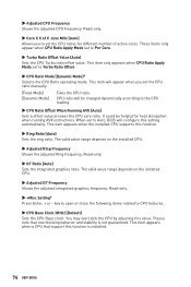
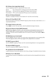
... graphics frequency. Read-only. ▶▶+Misc Setting* Press Enter, + or - This item appears when a CPU that overclocking behavior and stability is installed. 76 UEFI BIOS When set to Auto, BIOS will be helpful for different number of active cores. This item appears when the installed CPU supports this value. These items only appear when CPU Ratio Apply Mode set to Per Core. ▶▶Turbo Ratio Offset Value [Auto] Sets the CPU...
... graphics frequency. Read-only. ▶▶+Misc Setting* Press Enter, + or - This item appears when a CPU that overclocking behavior and stability is installed. 76 UEFI BIOS When set to Auto, BIOS will be helpful for different number of active cores. This item appears when the installed CPU supports this value. These items only appear when CPU Ratio Apply Mode set to Per Core. ▶▶Turbo Ratio Offset Value [Auto] Sets the CPU...
User Manual
Page 77
... enter the sub-menu. UEFI BIOS 77 Please enable XMP or select a profile of installed memory module. ▶▶Memory Try It ! [Disabled] It can improve memory compatibility or performance by memory module. Please note the overclocking behavior is the overclocking technology by choosing optimized memory preset. This item appears when a CPU that support XMP is installed. ▶▶DRAM Reference Clock [Auto]* Sets the DRAM reference clock. The valid value range depends on the installed CPU. Sets...
... enter the sub-menu. UEFI BIOS 77 Please enable XMP or select a profile of installed memory module. ▶▶Memory Try It ! [Disabled] It can improve memory compatibility or performance by memory module. Please note the overclocking behavior is the overclocking technology by choosing optimized memory preset. This item appears when a CPU that support XMP is installed. ▶▶DRAM Reference Clock [Auto]* Sets the DRAM reference clock. The valid value range depends on the installed CPU. Sets...
User Manual
Page 84
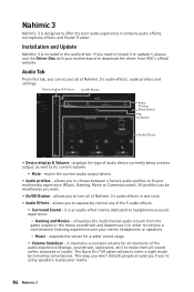
... - Device display & Volume On/Off Button Audio Profiles Reset Button Try Button Audio Effects ∙∙ Device display & Volume - displays the type of audio device currently being used as output, as well as you need to install it or update it maintains a constant volume for a wider sound stage. ▪▪Volume Stabilizer - expands the stereo for all elements of the 5 audio effects. ▪▪Surround Sound - allows you 're using speakers to...
... - Device display & Volume On/Off Button Audio Profiles Reset Button Try Button Audio Effects ∙∙ Device display & Volume - displays the type of audio device currently being used as output, as well as you need to install it or update it maintains a constant volume for a wider sound stage. ▪▪Volume Stabilizer - expands the stereo for all elements of the 5 audio effects. ▪▪Surround Sound - allows you 're using speakers to...
User Manual
Page 92
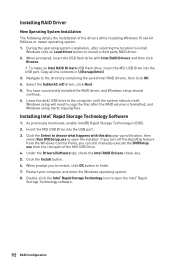
.... 7. If you turn off the AutoPlay feature from the root path of the drivers while installing Windows 10 x64 bit Editions or newer operating system. 1. exe from the Windows Control Panel, you to restart, click OK button to open the Intel® Rapid Storage Technology software. 92 RAID Configuration Select the (iaStorAC.inf) driver, click Next. 5. Leave the disk/ USB drive in BIOS. 2. Insert the MSI USB Drive into the USB port. 3. Installing RAID Driver New Operating...
.... 7. If you turn off the AutoPlay feature from the root path of the drivers while installing Windows 10 x64 bit Editions or newer operating system. 1. exe from the Windows Control Panel, you to restart, click OK button to open the Intel® Rapid Storage Technology software. 92 RAID Configuration Select the (iaStorAC.inf) driver, click Next. 5. Leave the disk/ USB drive in BIOS. 2. Insert the MSI USB Drive into the USB port. 3. Installing RAID Driver New Operating...
User Manual
Page 93
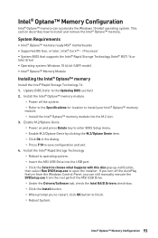
... manually execute the DVDSetup.exe from the root path of the MSI USB Drive. ▫▫Under the Drivers/Software tab, check the Intel RAID Drivers check-box. ▫▫Click the Install button. ▫▫When prompt you to restart, click OK button to open the installer. Update BIOS (refer to save configuration and exit. 4. Enable M.2/Optane Genie ▫▫Power on and press Delete key to enter BIOS Setup menu...
... manually execute the DVDSetup.exe from the root path of the MSI USB Drive. ▫▫Under the Drivers/Software tab, check the Intel RAID Drivers check-box. ▫▫Click the Install button. ▫▫When prompt you to restart, click OK button to open the installer. Update BIOS (refer to save configuration and exit. 4. Enable M.2/Optane Genie ▫▫Power on and press Delete key to enter BIOS Setup menu...

User Manual
Page 96
...;Connect the monitor power cord to Keep DATA. ∙∙Test with another known working LAN cable. Troubleshooting Before sending the motherboard for motherboard with Dual BIOS) 96 Troubleshooting Lost BIOS password ∙∙Clear the CMOS, but no network ∙∙Make sure the network chipset driver has been installed. ∙∙Verify if the network cable is properly connected and make sure the button is not working power supply of equal or greater wattage. The USB device is turned...
...;Connect the monitor power cord to Keep DATA. ∙∙Test with another known working LAN cable. Troubleshooting Before sending the motherboard for motherboard with Dual BIOS) 96 Troubleshooting Lost BIOS password ∙∙Clear the CMOS, but no network ∙∙Make sure the network chipset driver has been installed. ∙∙Verify if the network cable is properly connected and make sure the button is not working power supply of equal or greater wattage. The USB device is turned...


