
User Manual
Page 17
... 6.3mm Gold-plated stereo headphone jack y 5x OFC audio jacks y 1x Optical S/PDIF OUT connector Internal Connectors y 1x 24-pin ATX main power connector y 2x 8-pin ATX 12V power connectors y 1x 6-pin ATX PCIe power connector y 6x SATA 6Gb/s connectors y 3x M.2 slots (M-Key) y 1x U.2 port y 2x USB 3.1 Gen2 Type-C ports y 2x USB 3.1 Gen1...
... 6.3mm Gold-plated stereo headphone jack y 5x OFC audio jacks y 1x Optical S/PDIF OUT connector Internal Connectors y 1x 24-pin ATX main power connector y 2x 8-pin ATX 12V power connectors y 1x 6-pin ATX PCIe power connector y 6x SATA 6Gb/s connectors y 3x M.2 slots (M-Key) y 1x U.2 port y 2x USB 3.1 Gen2 Type-C ports y 2x USB 3.1 Gen1...

User Manual
Page 18
... y Displays system information NUVOTON NCT6797 Controller Chip Hardware Monitor y CPU/System temperature detection y CPU/System fan speed detection y CPU/System fan speed control Form Factor y E-ATX Form Factor y 12 in . (30.5 cm x 27.2 cm) BIOS Features y Dual BIOS y 2x 128 Mb flash y UEFI AMI BIOS y ACPI 6.1, SMBIOS 2.8 y Multi-language Continued on...
... y Displays system information NUVOTON NCT6797 Controller Chip Hardware Monitor y CPU/System temperature detection y CPU/System fan speed detection y CPU/System fan speed control Form Factor y E-ATX Form Factor y 12 in . (30.5 cm x 27.2 cm) BIOS Features y Dual BIOS y 2x 128 Mb flash y UEFI AMI BIOS y ACPI 6.1, SMBIOS 2.8 y Multi-language Continued on...
User Manual
Page 43
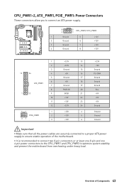
... and CPU_PWR2 to ensure stable operation of Components 43 Overview of the motherboard. CPU_PWR1~2, ATX_PWR1, PCIE_PWR1: Power Connectors These connectors allow you to connect an ATX power supply. 8 5 CPU_PWR1/ CPU_PWR2 4 1 1 Ground 5 2 Ground 6 3 Ground 7 4 Ground 8 +12V +12V +12V +12V 1 +3.3V 13 2 +3.3V 14 3 Ground 15 12 24 4 +... +5V +5V Ground Ground Ground Ground Important y Make sure that all the power cables are securely connected to a proper ATX power supply to optimize system stability and prevent the motherboard from overheating under heavy load.
... and CPU_PWR2 to ensure stable operation of Components 43 Overview of the motherboard. CPU_PWR1~2, ATX_PWR1, PCIE_PWR1: Power Connectors These connectors allow you to connect an ATX power supply. 8 5 CPU_PWR1/ CPU_PWR2 4 1 1 Ground 5 2 Ground 6 3 Ground 7 4 Ground 8 +12V +12V +12V +12V 1 +3.3V 13 2 +3.3V 14 3 Ground 15 12 24 4 +... +5V +5V Ground Ground Ground Ground Important y Make sure that all the power cables are securely connected to a proper ATX power supply to optimize system stability and prevent the motherboard from overheating under heavy load.
User Manual
Page 107
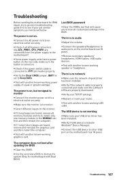
y Check if all ATX power connectors like ATX_PWR1, CPU_PWR1 are heard, remove and reinstall the graphics card and then restart the computer. y Verify the Clear CMOS jumper JBAT1 is ...
y Check if all ATX power connectors like ATX_PWR1, CPU_PWR1 are heard, remove and reinstall the graphics card and then restart the computer. y Verify the Clear CMOS jumper JBAT1 is ...


