User Manual
Page 11
... SATA1~6: SATA 6Gb/s Connectors 34 JFP1, JFP2: Front Panel Connectors 35 OC1: GAME BOOST Knob 35 OC_RT1: OC Retry Jumper 37 OC_FS1: OC Force Enter BIOS Jumper 37 JSLOW1: Slow Mode Booting Jumper 37 JLN1: Low Temperature Booting Jumper 37 CPU_PWR1~2, ATX_PWR1: Power Connectors 38 V-Check Points ...38 JUSB1, JUSB3: USB...
... SATA1~6: SATA 6Gb/s Connectors 34 JFP1, JFP2: Front Panel Connectors 35 OC1: GAME BOOST Knob 35 OC_RT1: OC Retry Jumper 37 OC_FS1: OC Force Enter BIOS Jumper 37 JSLOW1: Slow Mode Booting Jumper 37 JLN1: Low Temperature Booting Jumper 37 CPU_PWR1~2, ATX_PWR1: Power Connectors 38 V-Check Points ...38 JUSB1, JUSB3: USB...
User Manual
Page 12
... 41 JAUD1: Front Audio Connector 42 JCI1: Chassis Intrusion Connector 42 POWER1, RESET1: Power Button, Reset Button 43 JBAT1: Clear CMOS (Reset BIOS) Jumper 43 JRGB1, JRGB2, JRAINBOW1: RGB LED connectors 44 JCORSAIR1: CORSAIR Connector 45 Onboard LEDs ...46 EZ Debug LED...46 DIMM LEDs ... 53 Installing Drivers 53 Installing Utilities 53 MYSTIC LIGHT...54 Device LED effect control screen 54 Nahimic 3 ...57 BIOS Setup ...60 Entering BIOS Setup 60 Resetting BIOS...61 Updating BIOS...61 EZ Mode ...63 Advanced Mode ...65 SETTINGS...66 Advanced...66 Boot...71 Security ...72 Save & Exit...73...
... 41 JAUD1: Front Audio Connector 42 JCI1: Chassis Intrusion Connector 42 POWER1, RESET1: Power Button, Reset Button 43 JBAT1: Clear CMOS (Reset BIOS) Jumper 43 JRGB1, JRGB2, JRAINBOW1: RGB LED connectors 44 JCORSAIR1: CORSAIR Connector 45 Onboard LEDs ...46 EZ Debug LED...46 DIMM LEDs ... 53 Installing Drivers 53 Installing Utilities 53 MYSTIC LIGHT...54 Device LED effect control screen 54 Nahimic 3 ...57 BIOS Setup ...60 Entering BIOS Setup 60 Resetting BIOS...61 Updating BIOS...61 EZ Mode ...63 Advanced Mode ...65 SETTINGS...66 Advanced...66 Boot...71 Security ...72 Save & Exit...73...

User Manual
Page 14
.../ x4/ x4 modes y 3x PCIe 3.0 x1 slots y Supports 2-Way NVIDIA® SLI™ Technology y Supports 3-Way AMD® CrossFire™ Technology Intel® Z390 Chipset y 6x SATA 6Gb/s ports* y 3x M.2 slots (Key M)* ƒ M2_1 supports up to PCIe 3.0 x4 and SATA 6Gb/s, 2242/ 2260/ 2280/ 22110 ...intel.com for details. ** Before using Intel® Optane™ memory modules, please ensure that you have updated the drivers and BIOS to the latest version from MSI website. Continued on compatible memory. Please refer to page 34 for more information on next page 14 Specifications
.../ x4/ x4 modes y 3x PCIe 3.0 x1 slots y Supports 2-Way NVIDIA® SLI™ Technology y Supports 3-Way AMD® CrossFire™ Technology Intel® Z390 Chipset y 6x SATA 6Gb/s ports* y 3x M.2 slots (Key M)* ƒ M2_1 supports up to PCIe 3.0 x4 and SATA 6Gb/s, 2242/ 2260/ 2280/ 22110 ...intel.com for details. ** Before using Intel® Optane™ memory modules, please ensure that you have updated the drivers and BIOS to the latest version from MSI website. Continued on compatible memory. Please refer to page 34 for more information on next page 14 Specifications
User Manual
Page 16
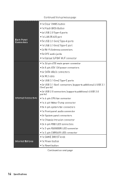
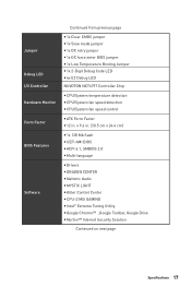
Continued from previous page Back Panel Connectors y 1x Clear CMOS button y 1x Flash BIOS Button y 4x USB 2.0 Type-A ports y 1x LAN (RJ45) port y 5x USB 3.1 Gen2 Type-A ports y 1x USB 3.1 Gen2 Type-C port y 2x Wi-Fi Antenna connectors y 5x ...
Continued from previous page Back Panel Connectors y 1x Clear CMOS button y 1x Flash BIOS Button y 4x USB 2.0 Type-A ports y 1x LAN (RJ45) port y 5x USB 3.1 Gen2 Type-A ports y 1x USB 3.1 Gen2 Type-C port y 2x Wi-Fi Antenna connectors y 5x ...
User Manual
Page 17
... Software Continued from previous page y 1x Clear CMOS jumper y 1x Slow mode jumper y 1x OC retry jumper y 1x OC force enter BIOS jumper y 1x Low Temperature Booting Jumper y 1x 2-Digit Debug Code LED y 4x EZ Debug LED NUVOTON NCT6797 Controller Chip y CPU/System ...ATX Form Factor y 12 in . (30.5 cm x 24.4 cm) y 1x 128 Mb flash y UEFI AMI BIOS y ACPI 6.1, SMBIOS 2.8 y Multi-language y Drivers y DRAGON CENTER y Nahimic Audio y MYSTIC LIGHT y Killer Control Center y CPU-Z MSI GAMING y Intel® Extreme Tuning Utility y Google Chrome™ ,Google Toolbar, Google Drive y Norton™ Internet ...
... Software Continued from previous page y 1x Clear CMOS jumper y 1x Slow mode jumper y 1x OC retry jumper y 1x OC force enter BIOS jumper y 1x Low Temperature Booting Jumper y 1x 2-Digit Debug Code LED y 4x EZ Debug LED NUVOTON NCT6797 Controller Chip y CPU/System ...ATX Form Factor y 12 in . (30.5 cm x 24.4 cm) y 1x 128 Mb flash y UEFI AMI BIOS y ACPI 6.1, SMBIOS 2.8 y Multi-language y Drivers y DRAGON CENTER y Nahimic Audio y MYSTIC LIGHT y Killer Control Center y CPU-Z MSI GAMING y Intel® Extreme Tuning Utility y Google Chrome™ ,Google Toolbar, Google Drive y Norton™ Internet ...
User Manual
Page 19
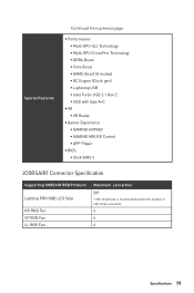
...; Intel Turbo USB 3.1 Gen 2 ƒ USB with type A+C y VR ƒ VR Ready y Gamer Experience ƒ GAMING HOTKEY ƒ GAMING MOUSE Control ƒ APP Player y BIOS ƒ Click BIOS 5 JCORSAIR1 Connector Specification Supporting CORSAIR RGB Products Lighting PRO RGB LED Strip HD RGB Fan SP RGB Fan LL RGB Fan Maximum connection 20...
...; Intel Turbo USB 3.1 Gen 2 ƒ USB with type A+C y VR ƒ VR Ready y Gamer Experience ƒ GAMING HOTKEY ƒ GAMING MOUSE Control ƒ APP Player y BIOS ƒ Click BIOS 5 JCORSAIR1 Connector Specification Supporting CORSAIR RGB Products Lighting PRO RGB LED Strip HD RGB Fan SP RGB Fan LL RGB Fan Maximum connection 20...

User Manual
Page 22
Press and hold the Clear CMOS button for Updating BIOS with Flash BIOS Button. Please refer to page 62 for about 5-10 seconds to reset BIOS to default values. LAN Port LED Status Table Link/ Activity LED Status Off Yellow Blinking Description No link Linked Data activity Speed LED Status Off ... Out ●●● Line-In/ Side Speaker Out ● Line-Out/ Front Speaker Out Mic In (●: connected, Blank: empty) 22 Rear I /O Panel Flash BIOS Port USB 2.0 LAN Clear CMOS button Wi-Fi Antenna connectors Audio Ports USB 3.1 Gen2 USB 3.1 Gen2 USB 3.1 Gen2 Type-C Flash...
Press and hold the Clear CMOS button for Updating BIOS with Flash BIOS Button. Please refer to page 62 for about 5-10 seconds to reset BIOS to default values. LAN Port LED Status Table Link/ Activity LED Status Off Yellow Blinking Description No link Linked Data activity Speed LED Status Off ... Out ●●● Line-In/ Side Speaker Out ● Line-Out/ Front Speaker Out Mic In (●: connected, Blank: empty) 22 Rear I /O Panel Flash BIOS Port USB 2.0 LAN Clear CMOS button Wi-Fi Antenna connectors Audio Ports USB 3.1 Gen2 USB 3.1 Gen2 USB 3.1 Gen2 Type-C Flash...
User Manual
Page 29
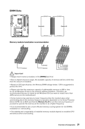
... that you to install 64-bit Windows OS if you want to install more efficient memory cooling system for 32-bit Windows OS due to BIOS and find the Memory Try It! DIMM Slots DIMMA1 DIMMB1 Channel A Channel B DIMMA2 Memory module installation recommendation DIMMB2 DIMMA2 DIMMB2 DIMMA2 DIMMB2 DIMMB1 DIMMA2 DIMMA1...
... that you to install 64-bit Windows OS if you want to install more efficient memory cooling system for 32-bit Windows OS due to BIOS and find the Memory Try It! DIMM Slots DIMMA1 DIMMB1 Channel A Channel B DIMMA2 Memory module installation recommendation DIMMB2 DIMMA2 DIMMB2 DIMMA2 DIMMB2 DIMMB1 DIMMA2 DIMMA1...
User Manual
Page 36
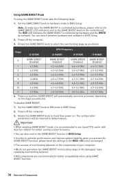
...GAME BOOST overclocking range or the damages/ risks caused by software. Power off the computer. 3. y The success of overclocking depends on . y MSI components are recommended for better cooling and performance. Stage i3-8350K CPU Frequency i5-8600K i7-8700K i7-8086K 0 GAME BOOST Disabled GAME BOOST ... RED LED indicates the GAME BOOST is controlled by hardware and the WHITE by overclocking behavior. y In order to hardware mode in the BIOS > OC menu unchanged. Power on and then GAME BOOST will be returned to 0 and then power on the components of Components Set the...
...GAME BOOST overclocking range or the damages/ risks caused by software. Power off the computer. 3. y The success of overclocking depends on . y MSI components are recommended for better cooling and performance. Stage i3-8350K CPU Frequency i5-8600K i7-8700K i7-8086K 0 GAME BOOST Disabled GAME BOOST ... RED LED indicates the GAME BOOST is controlled by hardware and the WHITE by overclocking behavior. y In order to hardware mode in the BIOS > OC menu unchanged. Power on and then GAME BOOST will be returned to 0 and then power on the components of Components Set the...
User Manual
Page 37
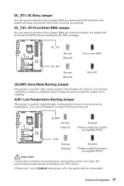
... retrying OC items until it Enabled to increase the boot success rate. Overview of Components 37 When you press and hold this jumper during BIOS POST.) JLN1 Normal (Default) Enabled (Please enable this button, the system will vary according to boot at a stable processor frequency and ...LN2 cooling solution, that provides the extreme overclocking conditions, to boot at an extreme low temperature. OC_FS1 Normal (Default) Force enter BIOS OC_RT1 Normal (Default) Retry OC JSLOW1: Slow Mode Booting Jumper This jumper is used for liquid nitrogen cooling system to the CPU version.
... retrying OC items until it Enabled to increase the boot success rate. Overview of Components 37 When you press and hold this jumper during BIOS POST.) JLN1 Normal (Default) Enabled (Please enable this button, the system will vary according to boot at a stable processor frequency and ...LN2 cooling solution, that provides the extreme overclocking conditions, to boot at an extreme low temperature. OC_FS1 Normal (Default) Force enter BIOS OC_RT1 Normal (Default) Retry OC JSLOW1: Slow Mode Booting Jumper This jumper is used for liquid nitrogen cooling system to the CPU version.
User Manual
Page 41
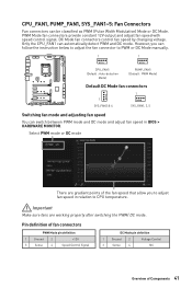
... mode and adjusting fan speed You can switch between PWM mode and DC mode and adjust fan speed in relation to adjust fan speed in BIOS > HARDWARE MONITOR.
... mode and adjusting fan speed You can switch between PWM mode and DC mode and adjust fan speed in relation to adjust fan speed in BIOS > HARDWARE MONITOR.

User Manual
Page 42
...key to select Yes. 6. JAUD1: Front Audio Connector This connector allows you to connect audio jacks on the chassis. 2. Set Chassis Intrusion to BIOS > SETTINGS > Security > Chassis Intrusion Configuration. 2. Go to Enabled. 5. Resetting the chassis intrusion warning 1. Connect the JCI1 connector to the ... Press F10 to save and exit and then press the Enter key to connect the chassis intrusion switch cable. Set Chassis Intrusion to BIOS > SETTINGS > Security > Chassis Intrusion Configuration. 4. Once the chassis cover is opened again, a warning message will be displayed on...
...key to select Yes. 6. JAUD1: Front Audio Connector This connector allows you to connect audio jacks on the chassis. 2. Set Chassis Intrusion to BIOS > SETTINGS > Security > Chassis Intrusion Configuration. 2. Go to Enabled. 5. Resetting the chassis intrusion warning 1. Connect the JCI1 connector to the ... Press F10 to save and exit and then press the Enter key to connect the chassis intrusion switch cable. Set Chassis Intrusion to BIOS > SETTINGS > Security > Chassis Intrusion Configuration. 4. Once the chassis cover is opened again, a warning message will be displayed on...

User Manual
Page 43
... the motherboard to reset the computer. Remove the jumper cap from a battery located on the computer. Reset Power button Reset button JBAT1: Clear CMOS (Reset BIOS) Jumper There is CMOS memory onboard that is external powered from JBAT1. 4. Keep Data (default) Clear CMOS/ Reset...
... the motherboard to reset the computer. Remove the jumper cap from a battery located on the computer. Reset Power button Reset button JBAT1: Clear CMOS (Reset BIOS) Jumper There is CMOS memory onboard that is external powered from JBAT1. 4. Keep Data (default) Clear CMOS/ Reset...
User Manual
Page 60
...: Save Overclocking Profile F10: Save Change and Reset* F12: Take a screenshot and save it provides the modification information. The system will reboot and enter BIOS setup directly. y In MSI Dragon Center application, click on the screen during the boot process. Function key F1: General Help F2: Add/ Remove a favorite item F3: Enter...
...: Save Overclocking Profile F10: Save Change and Reset* F12: Take a screenshot and save it provides the modification information. The system will reboot and enter BIOS setup directly. y In MSI Dragon Center application, click on the screen during the boot process. Function key F1: General Help F2: Add/ Remove a favorite item F3: Enter...
User Manual
Page 61
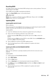
...100% completed, the system will restart automatically. Select BIOS Update. 3. BIOS Setup 61 After the flashing process is off before clearing CMOS data. Install and launch MSI DRAGON CENTER. 2. Resetting BIOS You might need to restore the default BIOS setting to solve certain problems. There are several ...ways to reset BIOS: y Go to BIOS and press F6 to the Clear CMOS jumper section for resetting BIOS. Please refer the following...
...100% completed, the system will restart automatically. Select BIOS Update. 3. BIOS Setup 61 After the flashing process is off before clearing CMOS data. Install and launch MSI DRAGON CENTER. 2. Resetting BIOS You might need to restore the default BIOS setting to solve certain problems. There are several ...ways to reset BIOS: y Go to BIOS and press F6 to the Clear CMOS jumper section for resetting BIOS. Please refer the following...
User Manual
Page 62
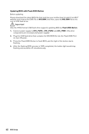
... button light would stop flashing and would be off simultaneously. 62 BIOS Setup Updating BIOS with Flash BIOS Button Before updating: Please download the latest BIOS file that contains the MSI.ROM file into the Flash BIOS Port on rear I/O panel. 3. And then, save the MSI.ROM file to CPU_PWR1,CPU_PWR2 and ATX_PWR1. (No other components are...
... button light would stop flashing and would be off simultaneously. 62 BIOS Setup Updating BIOS with Flash BIOS Button Before updating: Please download the latest BIOS file that contains the MSI.ROM file into the Flash BIOS Port on rear I/O panel. 3. And then, save the MSI.ROM file to CPU_PWR1,CPU_PWR2 and ATX_PWR1. (No other components are...
User Manual
Page 63
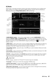
...show. Important In search page, only the F6, F10 and F12 function keys are available. y System information - You can move the device icons to search BIOS item by pressing the Setup Mode switch or F7 function key. y XMP switch - press this tab or the F12 key to take a screenshot and save... it provides the basic system information and allows you to select the language of BIOS setup. Move the mouse over a blank space and right click the mouse to enable/ disable the X.M.P. (Extreme Memory Profile). allows you to USB flash...
...show. Important In search page, only the F6, F10 and F12 function keys are available. y System information - You can move the device icons to search BIOS item by pressing the Setup Mode switch or F7 function key. y XMP switch - press this tab or the F12 key to take a screenshot and save... it provides the basic system information and allows you to select the language of BIOS setup. Move the mouse over a blank space and right click the mouse to enable/ disable the X.M.P. (Extreme Memory Profile). allows you to USB flash...
User Manual
Page 64
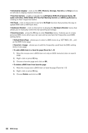
...on this button to display the Hardware Monitor menu that provides the way to enter Favorites menu. Move the mouse over a BIOS item not only on BIOS menu but also on this button to perform M-Flash function that allows you to a favorite page (Favorite 1~5) 1. Choose ...display related information. Right-click or press F2 key. 3. y Information display - y Function buttons - allows you can save and access favorite/ frequently-used BIOS setting items. ƒ Default HomePage - click on search page. 2. click on the CPU, Memory, Storage, Fan Info and Help buttons on OK. &#...
...on this button to display the Hardware Monitor menu that provides the way to enter Favorites menu. Move the mouse over a BIOS item not only on BIOS menu but also on this button to perform M-Flash function that allows you to a favorite page (Favorite 1~5) 1. Choose ...display related information. Right-click or press F2 key. 3. y Information display - y Function buttons - allows you can save and access favorite/ frequently-used BIOS setting items. ƒ Default HomePage - click on search page. 2. click on the CPU, Memory, Storage, Fan Info and Help buttons on OK. &#...
User Manual
Page 65
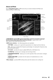
... and voltage. Increasing the frequency may get better performance. ƒ M-FLASH - provides BIOS setting items and information to update BIOS with a USB flash drive. ƒ OC PROFILE - BIOS Setup 65 the following options are available: ƒ SETTINGS - provides the way to ...be configured. XMP switch Setup Mode switch Screenshot GAME BOOST switch Search Language System information Boot device priority bar BIOS menu selection BIOS menu selection Menu display y GAME BOOST switch/ XMP switch/ Setup Mode switch/ Screenshot/ Language/ Search/ System information/ ...
... and voltage. Increasing the frequency may get better performance. ƒ M-FLASH - provides BIOS setting items and information to update BIOS with a USB flash drive. ƒ OC PROFILE - BIOS Setup 65 the following options are available: ƒ SETTINGS - provides the way to ...be configured. XMP switch Setup Mode switch Screenshot GAME BOOST switch Search Language System information Boot device priority bar BIOS menu selection BIOS menu selection Menu display y GAME BOOST switch/ XMP switch/ Setup Mode switch/ Screenshot/ Language/ Search/ System information/ ...

User Manual
Page 66
...SATA/ M.2 devices. f SATA PortX/ M2_X Shows the information of the week, from Jan. The date from 1 to 31 can be keyed by BIOS. Use tab key to switch between time elements. Read-only. Use tab key to switch between date elements. f System Information Shows detailed system information,... including CPU type, BIOS version, and Memory (read only). SETTINGS System Status f System Date Sets the system date. The month from Sun to enter the sub-menu...
...SATA/ M.2 devices. f SATA PortX/ M2_X Shows the information of the week, from Jan. The date from 1 to 31 can be keyed by BIOS. Use tab key to switch between time elements. Read-only. Use tab key to switch between date elements. f System Information Shows detailed system information,... including CPU type, BIOS version, and Memory (read only). SETTINGS System Status f System Date Sets the system date. The month from Sun to enter the sub-menu...


