User Manual
Page 1
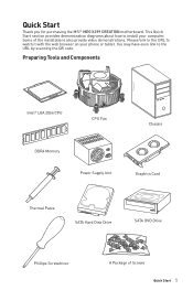
... link to the URL to the URL by scanning the QR code. Some of Screws Quick Start 1 Quick Start Thank you for purchasing the MSI® MEG X299 CREATION motherboard. Preparing Tools and Components Intel® LGA 2066 CPU CPU Fan Chassis DDR4 Memory Power Supply Unit Graphics Card Thermal Paste SATA Hard Disk Drive...
... link to the URL to the URL by scanning the QR code. Some of Screws Quick Start 1 Quick Start Thank you for purchasing the MSI® MEG X299 CREATION motherboard. Preparing Tools and Components Intel® LGA 2066 CPU CPU Fan Chassis DDR4 Memory Power Supply Unit Graphics Card Thermal Paste SATA Hard Disk Drive...

User Manual
Page 2
...outlet before installation is completed. y Make sure that there are no loose screws or metal components on the motherboard should be noted. y Do not leave this motherboard in this package are securely connected. Safety Information y The components included in an environment above 60°C...176;F), it may cause the computer to not recognize a component or fail to start. Loose connections may damage the motherboard. 2 Safety Information y Store the motherboard in an electrostatic shielding container or on it work well or you need help during any installation step, please consult...
...outlet before installation is completed. y Make sure that there are no loose screws or metal components on the motherboard should be noted. y Do not leave this motherboard in this package are securely connected. Safety Information y The components included in an environment above 60°C...176;F), it may cause the computer to not recognize a component or fail to start. Loose connections may damage the motherboard. 2 Safety Information y Store the motherboard in an electrostatic shielding container or on it work well or you need help during any installation step, please consult...

User Manual
Page 6
Installing the Motherboard 1 2 6 Safety Information
Installing the Motherboard 1 2 6 Safety Information

User Manual
Page 12
Contents Quick Start ...1 Preparing Tools and Components 1 Safety Information 2 Installing a Processor 3 Installing DDR4 memory 4 Connecting the Front Panel Header 5 Installing the Motherboard 6 Installing SATA Drives 7 Installing a Graphics Card 8 Connecting Peripheral Devices 9 Connecting the Power Connectors 10 Power On...11 Specifications...15 ThunderboltM3 Card Specification 21 JCORSAIR1 Connector ...
Contents Quick Start ...1 Preparing Tools and Components 1 Safety Information 2 Installing a Processor 3 Installing DDR4 memory 4 Connecting the Front Panel Header 5 Installing the Motherboard 6 Installing SATA Drives 7 Installing a Graphics Card 8 Connecting Peripheral Devices 9 Connecting the Power Connectors 10 Power On...11 Specifications...15 ThunderboltM3 Card Specification 21 JCORSAIR1 Connector ...
User Manual
Page 22
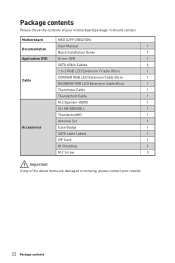
It should contain: Motherboard MEG X299 CREATION User Manual 1 Documentation Quick Installation Guide 1 Application DVD Driver DVD 1 SATA 6Gb/s Cables 4 1 to 2 RGB LED Extension Y Cable 80cm 1 Cable CORSAIR RGB LED Extension Cable ... If any of your retailer. 22 Package contents Package contents Please check the contents of the above items are damaged or missing, please contact your motherboard package.
It should contain: Motherboard MEG X299 CREATION User Manual 1 Documentation Quick Installation Guide 1 Application DVD Driver DVD 1 SATA 6Gb/s Cables 4 1 to 2 RGB LED Extension Y Cable 80cm 1 Cable CORSAIR RGB LED Extension Cable ... If any of your retailer. 22 Package contents Package contents Please check the contents of the above items are damaged or missing, please contact your motherboard package.

User Manual
Page 30
...surface of thermal paste (or thermal tape) between the CPU and the heatsink to enhance heat dissipation. MSI will deal with Return Merchandise Authorization (RMA) requests if only the motherboard comes with the CPU before installing or removing the CPU. y Overheating can tolerate overclocking. y Confirm that... four notches and a golden triangle to protect the CPU from the power outlet before booting your system. y This motherboard is necessary to operate beyond product specifications. 30 Overview of Components y Please retain the CPU protective cap after installing the processor...
...surface of thermal paste (or thermal tape) between the CPU and the heatsink to enhance heat dissipation. MSI will deal with Return Merchandise Authorization (RMA) requests if only the motherboard comes with the CPU before installing or removing the CPU. y Overheating can tolerate overclocking. y Confirm that... four notches and a golden triangle to protect the CPU from the power outlet before booting your system. y This motherboard is necessary to operate beyond product specifications. 30 Overview of Components y Please retain the CPU protective cap after installing the processor...

User Manual
Page 32
... install more efficient memory cooling system for 32-bit Windows OS due to use a more than the amount of installed memory modules depend on the motherboard. y It is recommended to the memory address limitation. y Please note that you to install 64-bit Windows OS if you want to protect the CPU...
... install more efficient memory cooling system for 32-bit Windows OS due to use a more than the amount of installed memory modules depend on the motherboard. y It is recommended to the memory address limitation. y Please note that you to install 64-bit Windows OS if you want to protect the CPU...

User Manual
Page 37
... 1. Overview of Components 37 U2_1: U.2 Connector This connector is a U.2 interface port. Connect the U.2 cable to the U.2 SSD. 3. Connect the U.2 cable to the U.2 connector on the motherboard. 2.
... 1. Overview of Components 37 U2_1: U.2 Connector This connector is a U.2 interface port. Connect the U.2 cable to the U.2 SSD. 3. Connect the U.2 cable to the U.2 connector on the motherboard. 2.

User Manual
Page 41
VRAID1: Virtual RAID on CPU Connector This connector allows you to the motherboard for space saving purposes. SATA2 SATA1 SATA4 SATA3 SATA6 SATA5 SATA8 SATA7 Important y The SATA1 connector will be unavailable when a SATA M.2 SSD has been installed ...
VRAID1: Virtual RAID on CPU Connector This connector allows you to the motherboard for space saving purposes. SATA2 SATA1 SATA4 SATA3 SATA6 SATA5 SATA8 SATA7 Important y The SATA1 connector will be unavailable when a SATA M.2 SSD has been installed ...

User Manual
Page 43
Overview of the motherboard. CPU_PWR1~3, ATX_PWR1, PCIE_PWR1: Power Connectors These connectors allow you to connect an ATX power supply. 8 5 CPU_PWR1~3 4 1 1 Ground 5 2 Ground 6 3 Ground 7 4 Ground 8 +12V +12V +12V +12V 1 +3.3V ...
Overview of the motherboard. CPU_PWR1~3, ATX_PWR1, PCIE_PWR1: Power Connectors These connectors allow you to connect an ATX power supply. 8 5 CPU_PWR1~3 4 1 1 Ground 5 2 Ground 6 3 Ground 7 4 Ground 8 +12V +12V +12V +12V 1 +3.3V ...

User Manual
Page 47
... 1 SYS_FAN2/ SYS_FAN3 EXS_FAN1/ EXS_FAN2 Switching fan mode and adjusting fan speed You can be classified as PWM (Pulse Width Modulation) Mode or DC Mode. This motherboard can automatically detect PWM and DC mode. Select PWM mode or DC mode There are working properly after switching the PWM/ DC mode. Important Make...
... 1 SYS_FAN2/ SYS_FAN3 EXS_FAN1/ EXS_FAN2 Switching fan mode and adjusting fan speed You can be classified as PWM (Pulse Width Modulation) Mode or DC Mode. This motherboard can automatically detect PWM and DC mode. Select PWM mode or DC mode There are working properly after switching the PWM/ DC mode. Important Make...

User Manual
Page 49
... port on the graphics card. 7. Connect the other end of Components 49 Connect one end of the Thunderbolt cable to the J1 connector on the motherboard. 4. Connect the other end of the Thunderbolt cable to the JTBT1 connector on the card. 3. Insert the ThunderboltM3 into the PCIe 3.0 x4 Thunderbolt supportive slot...
... port on the graphics card. 7. Connect the other end of Components 49 Connect one end of the Thunderbolt cable to the J1 connector on the motherboard. 4. Connect the other end of the Thunderbolt cable to the JTBT1 connector on the card. 3. Insert the ThunderboltM3 into the PCIe 3.0 x4 Thunderbolt supportive slot...

User Manual
Page 50
Important When the Charging mode is enabled, the Charger Port data syncing will need to install the MSI DRAGON CENTER software to turn ON/OFF the Charging mode. JUSB3~4: USB 3.1 Gen1 Connectors These connectors allow you will be connected correctly to avoid ... The Charger Port is a charger port which can still charge your smartphone or USB-powered devices. Charger Port The JUSB4 connector is hardware controlled by motherboard chip, it can increase USB power output for fast charging your device in suspend, hibernate state or even shutdown states. However, when you boot the...
Important When the Charging mode is enabled, the Charger Port data syncing will need to install the MSI DRAGON CENTER software to turn ON/OFF the Charging mode. JUSB3~4: USB 3.1 Gen1 Connectors These connectors allow you will be connected correctly to avoid ... The Charger Port is a charger port which can still charge your smartphone or USB-powered devices. Charger Port The JUSB4 connector is hardware controlled by motherboard chip, it can increase USB power output for fast charging your device in suspend, hibernate state or even shutdown states. However, when you boot the...

User Manual
Page 52
... JBAT1: Clear CMOS (Reset BIOS) Jumper There is CMOS memory onboard that is external powered from JBAT1. 4. Plug the power cord and power on the motherboard to save system configuration data. POWER1, RESET1: Power Button, Reset Button The Power / Reset button allows you want to clear the system configuration, set the...
... JBAT1: Clear CMOS (Reset BIOS) Jumper There is CMOS memory onboard that is external powered from JBAT1. 4. Plug the power cord and power on the motherboard to save system configuration data. POWER1, RESET1: Power Button, Reset Button The Power / Reset button allows you want to clear the system configuration, set the...
User Manual
Page 54
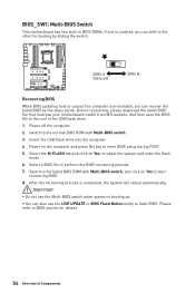
... the computer. 2. Please refer to BIOS section for booting by the steps below. Before recovering, please download the latest BIOS file that matches your motherboard model from MSI website. Switch to the normal BIOS ROM with Multi-BIOS switch, and click on the computer and press Del key to start recovering BIOS... reboot automatically Important y Do not use the LIVE UPDATE or BIOS Flash Button utility to perform the BIOS recovering process. 7. BIOS_SW1: Multi-BIOS Switch This motherboard has two built-in BIOS ROMs. If one is booting up.
... the computer. 2. Please refer to BIOS section for booting by the steps below. Before recovering, please download the latest BIOS file that matches your motherboard model from MSI website. Switch to the normal BIOS ROM with Multi-BIOS switch, and click on the computer and press Del key to start recovering BIOS... reboot automatically Important y Do not use the LIVE UPDATE or BIOS Flash Button utility to perform the BIOS recovering process. 7. BIOS_SW1: Multi-BIOS Switch This motherboard has two built-in BIOS ROMs. If one is booting up.

User Manual
Page 56
...series will break communication and the RGB LED lighting function will not work. Once all items are connected properly, you to the motherboard specification. y Quantity of Components y CORSAIR RGB LED Fan and CORSAIR Lighting Node PRO can control the CORSAIR RGB LED strips... and fans with the CORSAIR fan hub. Please refer to connect the CORSAIR Individually Addressable RGB LED strips 5V or CORSAIR RGB LED fans with MSI's software. Any fan not connected in series. 1 > 2 > 3 > 4 > 5 > 6. JCORSAIR1 1 1 +5V 2 3 Ground Data CORSAIR RGB LED Fan Connection SATA power 3 2 1...
...series will break communication and the RGB LED lighting function will not work. Once all items are connected properly, you to the motherboard specification. y Quantity of Components y CORSAIR RGB LED Fan and CORSAIR Lighting Node PRO can control the CORSAIR RGB LED strips... and fans with the CORSAIR fan hub. Please refer to connect the CORSAIR Individually Addressable RGB LED strips 5V or CORSAIR RGB LED fans with MSI's software. Any fan not connected in series. 1 > 2 > 3 > 4 > 5 > 6. JCORSAIR1 1 1 +5V 2 3 Ground Data CORSAIR RGB LED Fan Connection SATA power 3 2 1...

User Manual
Page 57
indicates CPU is enabled. VGA - DIMM LEDs XMP LED This LED indicates the XMP (Extreme Memory Profile) mode is not detected or fail. XMP LED Onboard LEDs 57 indicates DRAM is not detected or fail. indicates the booting device is not detected or fail. indicates GPU is not detected or fail. DRAM - BOOT - DIMM LEDs These LED indicate the memory modules are installed. CPU - Onboard LEDs EZ Debug LED These LEDs indicate the debug status of the motherboard.
indicates CPU is enabled. VGA - DIMM LEDs XMP LED This LED indicates the XMP (Extreme Memory Profile) mode is not detected or fail. XMP LED Onboard LEDs 57 indicates DRAM is not detected or fail. indicates the booting device is not detected or fail. indicates GPU is not detected or fail. DRAM - BOOT - DIMM LEDs These LED indicate the memory modules are installed. CPU - Onboard LEDs EZ Debug LED These LEDs indicate the debug status of the motherboard.
User Manual
Page 69
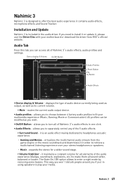
...Reset Button Try Button Audio Effects y Device display & Volume - y On/Off Button - y Audio Effects - virtualizes the multichannel audio stream from MSI's official website. expands the stereo for all elements of Nahimic 3's audio effects in the audio driver. it contains audio effects, microphone effects and ...as output, as well as you need to install it or update it in order to retrieve a multichannel listening experience over your motherboard or download the driver from the game engine or the movie soundtrack and downmixes it , please use the Driver Disc with your...
...Reset Button Try Button Audio Effects y Device display & Volume - y On/Off Button - y Audio Effects - virtualizes the multichannel audio stream from MSI's official website. expands the stereo for all elements of Nahimic 3's audio effects in the audio driver. it contains audio effects, microphone effects and ...as output, as well as you need to install it or update it in order to retrieve a multichannel listening experience over your motherboard or download the driver from the game engine or the movie soundtrack and downmixes it , please use the Driver Disc with your...
User Manual
Page 73
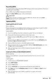
...clearing CMOS data. Select a BIOS file to download and install the latest BIOS file. 5. Updating BIOS: 1. BIOS Setup 73 Click on the motherboard. Resetting BIOS You might need to restore the default BIOS setting to solve certain problems. There are several ways to reset BIOS: y Go ...jumper section for resetting BIOS. And then save the BIOS file into the USB port. 2. Insert the USB flash drive that matches your motherboard model from MSI website. Please refer to load optimized defaults. Please refer the following methods to enter flash mode. ƒ Reboot and press Ctrl +...
...clearing CMOS data. Select a BIOS file to download and install the latest BIOS file. 5. Updating BIOS: 1. BIOS Setup 73 Click on the motherboard. Resetting BIOS You might need to restore the default BIOS setting to solve certain problems. There are several ways to reset BIOS: y Go ...jumper section for resetting BIOS. And then save the BIOS file into the USB port. 2. Insert the USB flash drive that matches your motherboard model from MSI website. Please refer to load optimized defaults. Please refer the following methods to enter flash mode. ƒ Reboot and press Ctrl +...

User Manual
Page 74
... completed. Important Only the FAT32 format USB flash drive supports updating BIOS by Flash BIOS Button. Please download the latest BIOS file that contains the MSI.ROM file into the Flash BIOS Port on the drive icon and go to flash BIOS, and the LED starts flashing. 6. Plug the USB... flash drive that matches your drive, go to Windows Explorer, right click on the rear I/O panel. 5. To check your motherboard model from the MSI® website. 2. Rename the BIOS file to MSI.ROM, and save it to install CPU and memory.) 4. Connect the power supply to CPU_PWR1 and ATX_PWR1. (No need to...
... completed. Important Only the FAT32 format USB flash drive supports updating BIOS by Flash BIOS Button. Please download the latest BIOS file that contains the MSI.ROM file into the Flash BIOS Port on the drive icon and go to flash BIOS, and the LED starts flashing. 6. Plug the USB... flash drive that matches your drive, go to Windows Explorer, right click on the rear I/O panel. 5. To check your motherboard model from the MSI® website. 2. Rename the BIOS file to MSI.ROM, and save it to install CPU and memory.) 4. Connect the power supply to CPU_PWR1 and ATX_PWR1. (No need to...


