User Manual
Page 1
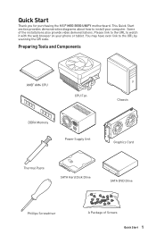
... tablet. This Quick Start section provides demonstration diagrams about how to the URL by scanning the QR code. Quick Start Thank you for purchasing the MSI® MEG B550 UNIFY motherboard. Some of Screws Quick Start 1
... tablet. This Quick Start section provides demonstration diagrams about how to the URL by scanning the QR code. Quick Start Thank you for purchasing the MSI® MEG B550 UNIFY motherboard. Some of Screws Quick Start 1
User Manual
Page 2
...power supply and unplug the power cord from the power outlet before installing or removing any of the following situations arises, get the motherboard checked by touching another metal object before installation is completed. Do not place anything over the power cord. ∙∙All ...cautions and warnings on it work according to user guide. ▪▪The motherboard has been dropped and damaged. ▪▪The motherboard has obvious sign of static electricity by service personnel: ▪▪Liquid has penetrated into the computer. ▪...
...power supply and unplug the power cord from the power outlet before installing or removing any of the following situations arises, get the motherboard checked by touching another metal object before installation is completed. Do not place anything over the power cord. ∙∙All ...cautions and warnings on it work according to user guide. ▪▪The motherboard has been dropped and damaged. ▪▪The motherboard has obvious sign of static electricity by service personnel: ▪▪Liquid has penetrated into the computer. ▪...
User Manual
Page 7
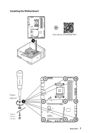
Installing the Motherboard ⚽ ⚽ https://youtu.be/wWI6Qt51Wnc 1 Torque: 3 kgf·cm* 2 *3 kgf·cm = 0.3 N·m = 2.6 lbf·in BAT1 Quick Start 7
Installing the Motherboard ⚽ ⚽ https://youtu.be/wWI6Qt51Wnc 1 Torque: 3 kgf·cm* 2 *3 kgf·cm = 0.3 N·m = 2.6 lbf·in BAT1 Quick Start 7
User Manual
Page 13
Contents Quick Start...1 Preparing Tools and Components 1 Safety Information 2 Installing a Processor 3 Installing DDR4 memory 5 Connecting the Front Panel Header 6 Installing the Motherboard 7 Connecting the Power Connectors 8 Installing SATA Drives 9 Installing a Graphics Card 10 Connecting Peripheral Devices 11 Power On...12 Specifications...15 Package contents 22 Block Diagram ......
Contents Quick Start...1 Preparing Tools and Components 1 Safety Information 2 Installing a Processor 3 Installing DDR4 memory 5 Connecting the Front Panel Header 6 Installing the Motherboard 7 Connecting the Power Connectors 8 Installing SATA Drives 9 Installing a Graphics Card 10 Connecting Peripheral Devices 11 Power On...12 Specifications...15 Package contents 22 Block Diagram ......
User Manual
Page 22
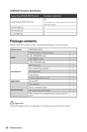
...It should contain: Motherboard Cable Accessories Application Documentation MEG B550 UNIFY SATA 6G cables (2 cables/pack) 1 LED JRAINBOW cable 1 LED JRGB Y cable 1 LED JCORSAIR cable 1 Wi-Fi Antenna 1 M.2 screws (3 pcs./pack) 2 DIY Stands Set 1 Case Badge 1 Product registration card 1 Driver DVD 1 User manual 1 Quick installation guide 1 DIY Stands Set Quick Guide 1 MSI components compatibility & ...the number of LED strips exceeds 8. 6 6 6 Package contents Please check the contents of the above items are damaged or missing, please contact your motherboard package.
...It should contain: Motherboard Cable Accessories Application Documentation MEG B550 UNIFY SATA 6G cables (2 cables/pack) 1 LED JRAINBOW cable 1 LED JRGB Y cable 1 LED JCORSAIR cable 1 Wi-Fi Antenna 1 M.2 screws (3 pcs./pack) 2 DIY Stands Set 1 Case Badge 1 Product registration card 1 Driver DVD 1 User manual 1 Quick installation guide 1 DIY Stands Set Quick Guide 1 MSI components compatibility & ...the number of LED strips exceeds 8. 6 6 6 Package contents Please check the contents of the above items are damaged or missing, please contact your motherboard package.
User Manual
Page 30
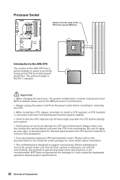
... heat dissipation. ∙∙If you purchased a separate CPU and heatsink/ cooler, Please refer to the documentation in correctly lining up the CPU for motherboard placement. MSI® does not guarantee the damages or risks caused by inadequate operation beyond product specifications is designed to assist in the heatsink/ cooler package for...
... heat dissipation. ∙∙If you purchased a separate CPU and heatsink/ cooler, Please refer to the documentation in correctly lining up the CPU for motherboard placement. MSI® does not guarantee the damages or risks caused by inadequate operation beyond product specifications is designed to assist in the heatsink/ cooler package for...
User Manual
Page 38
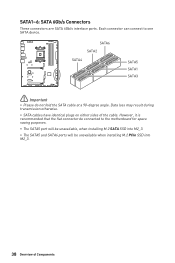
.... Data loss may result during transmission otherwise. ∙∙SATA cables have identical plugs on either sides of Components Each connector can connect to the motherboard for space saving purposes. ∙∙The SATA5 port will be unavailable, when installing M.2 SATA SSD into M2_3. ∙∙The SATA5 and SATA6 ports...
.... Data loss may result during transmission otherwise. ∙∙SATA cables have identical plugs on either sides of Components Each connector can connect to the motherboard for space saving purposes. ∙∙The SATA5 port will be unavailable, when installing M.2 SATA SSD into M2_3. ∙∙The SATA5 and SATA6 ports...
User Manual
Page 40
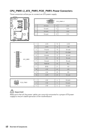
... 6 Ground ⚠⚠Important Make sure that all the power cables are securely connected to a proper ATX power supply to ensure stable operation of the motherboard. 40 Overview of Components
... 6 Ground ⚠⚠Important Make sure that all the power cables are securely connected to a proper ATX power supply to ensure stable operation of the motherboard. 40 Overview of Components
User Manual
Page 45
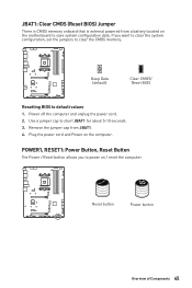
... is CMOS memory onboard that is external powered from JBAT1. 4. Plug the power cord and Power on the computer. If you to power on the motherboard to clear the CMOS memory.
... is CMOS memory onboard that is external powered from JBAT1. 4. Plug the power cord and Power on the computer. If you to power on the motherboard to clear the CMOS memory.
User Manual
Page 48
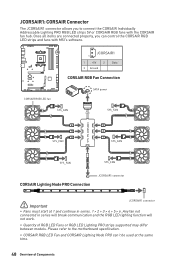
... not connected in series. 1 > 2 > 3 > 4 > 5 > 6. Once all items are connected properly, you to the motherboard specification. ∙∙CORSAIR RGB LED Fan and CORSAIR Lighting Node PRO can control the CORSAIR RGB LED strips and fans with the CORSAIR... fan hub. Please refer to connect the CORSAIR Individually Addressable Lighting PRO RGB LED strips 5V or CORSAIR RGB fans with MSI's software. JCORSAIR1 1 1 +5V 2 3 Ground Data CORSAIR RGB Fan Connection CORSAIR RGB LED fan SATA power SYS_FAN SYS_FAN CORSAIR fan hub 4 5 6 SYS_FAN 3 2 1 SYS_FAN...
... not connected in series. 1 > 2 > 3 > 4 > 5 > 6. Once all items are connected properly, you to the motherboard specification. ∙∙CORSAIR RGB LED Fan and CORSAIR Lighting Node PRO can control the CORSAIR RGB LED strips and fans with the CORSAIR... fan hub. Please refer to connect the CORSAIR Individually Addressable Lighting PRO RGB LED strips 5V or CORSAIR RGB fans with MSI's software. JCORSAIR1 1 1 +5V 2 3 Ground Data CORSAIR RGB Fan Connection CORSAIR RGB LED fan SATA power SYS_FAN SYS_FAN CORSAIR fan hub 4 5 6 SYS_FAN 3 2 1 SYS_FAN...
User Manual
Page 49
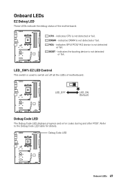
.... Debug Code LED Onboard LEDs 49 indicates the booting device is not detected or fail. Refer to switch on/ off all the LEDs of the motherboard. Onboard LEDs EZ Debug LED These LEDs indicate the debug status of...
.... Debug Code LED Onboard LEDs 49 indicates the booting device is not detected or fail. Refer to switch on/ off all the LEDs of the motherboard. Onboard LEDs EZ Debug LED These LEDs indicate the debug status of...
User Manual
Page 56
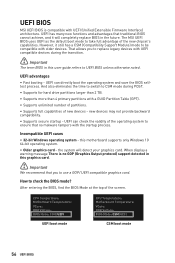
...GOP (Graphics Output protocol) support detected in the future. When display a warning message There is compatible with UEFI (Unified Extensible Firmware Interface) architecture. The MSI UEFI BIOS uses UEFI as the default boot mode to CSM mode during the transition. ⚠⚠Important The ... still has a CSM (Compatibility Support Module) mode to check the BIOS mode? CPU Temperature: Motherboard Temperature: VCore: DDR Voltage: BIOS Mode: CSM/UEFI UEFI boot mode CPU Temperature: Motherboard Temperature: VCore: DDR Voltage: BIOS Mode: CSM/UEFI CSM boot mode 56 UEFI BIOS How ...
...GOP (Graphics Output protocol) support detected in the future. When display a warning message There is compatible with UEFI (Unified Extensible Firmware Interface) architecture. The MSI UEFI BIOS uses UEFI as the default boot mode to CSM mode during the transition. ⚠⚠Important The ... still has a CSM (Compatibility Support Module) mode to check the BIOS mode? CPU Temperature: Motherboard Temperature: VCore: DDR Voltage: BIOS Mode: CSM/UEFI UEFI boot mode CPU Temperature: Motherboard Temperature: VCore: DDR Voltage: BIOS Mode: CSM/UEFI CSM boot mode 56 UEFI BIOS How ...
User Manual
Page 58
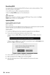
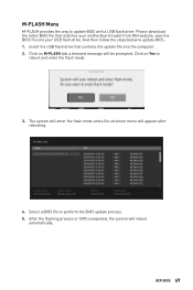
...click on Yes to reboot the system. Please refer to perform the BIOS update process. 4. Insert the USB flash drive that matches your motherboard model from MSI website. Please refer the following methods to enter flash mode. ▪▪Reboot and press Ctrl + F5 key during POST to enter ...Clear CMOS jumper on Yes to start recovering BIOS. 5. After the flashing process is off before clearing CMOS data. When prompted click on the motherboard. ⚠⚠Important Be sure the computer is 100% completed, the system will reboot automatically. 58 UEFI BIOS Select a BIOS file to ...
...click on Yes to reboot the system. Please refer to perform the BIOS update process. 4. Insert the USB flash drive that matches your motherboard model from MSI website. Please refer the following methods to enter flash mode. ▪▪Reboot and press Ctrl + F5 key during POST to enter ...Clear CMOS jumper on Yes to start recovering BIOS. 5. After the flashing process is off before clearing CMOS data. When prompted click on the motherboard. ⚠⚠Important Be sure the computer is 100% completed, the system will reboot automatically. 58 UEFI BIOS Select a BIOS file to ...
User Manual
Page 59
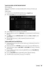
... BIOS file. 5. After the flashing process is completed. Connect the power supply to CPU_PWR1 and ATX_PWR1. (No need to the root of your motherboard model from the MSI® website. 2. UEFI BIOS 59 Updating BIOS: 1. Select the BIOS file and click on Scan button to start updating BIOS. 6. Updating ... on the rear I/O panel. 5. Click Next and choose In Windows mode. Press the Flash BIOS Button to Support page. 2. Install and launch MSI DRAGON CENTER and go to flash BIOS, and the LED starts flashing. 6. And then click Next and Start to search the latest BIOS file. 4.
... BIOS file. 5. After the flashing process is completed. Connect the power supply to CPU_PWR1 and ATX_PWR1. (No need to the root of your motherboard model from the MSI® website. 2. UEFI BIOS 59 Updating BIOS: 1. Select the BIOS file and click on Scan button to start updating BIOS. 6. Updating ... on the rear I/O panel. 5. Click Next and choose In Windows mode. Press the Flash BIOS Button to Support page. 2. Install and launch MSI DRAGON CENTER and go to flash BIOS, and the LED starts flashing. 6. And then click Next and Start to search the latest BIOS file. 4.
User Manual
Page 60
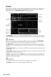
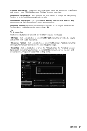
... between Advanced mode and EZ mode. ∙∙ Screenshot - press this tab or the F7 key to overclock. allows you to select language of the motherboard and CPU are supporting this tab or the F12 key to take a screenshot and save it to enter the search page. EZ Mode At EZ...
... between Advanced mode and EZ mode. ∙∙ Screenshot - press this tab or the F7 key to overclock. allows you to select language of the motherboard and CPU are supporting this tab or the F12 key to take a screenshot and save it to enter the search page. EZ Mode At EZ...
User Manual
Page 61
.... ∙∙ Boot device priority bar - click on this button to enter the Hardware Monitor menu that provides the way to update BIOS with the motherboard you to manually control the fan speed by clicking on this button to enter the M-Flash menu that allows you purchased. ∙∙ M-Flash - The...
.... ∙∙ Boot device priority bar - click on this button to enter the Hardware Monitor menu that provides the way to update BIOS with the motherboard you to manually control the fan speed by clicking on this button to enter the M-Flash menu that allows you purchased. ∙∙ M-Flash - The...

User Manual
Page 63
... system. ▪▪BOARD EXPLORER - provides BIOS setting items and information to set the speeds of fans and monitor voltages of installed devices on this motherboard. ∙∙ Menu display - allows you to specify the parameters for chipset and boot devices. ▪▪OC - allows you to adjust the frequency and...
... system. ▪▪BOARD EXPLORER - provides BIOS setting items and information to set the speeds of fans and monitor voltages of installed devices on this motherboard. ∙∙ Menu display - allows you to specify the parameters for chipset and boot devices. ▪▪OC - allows you to adjust the frequency and...
User Manual
Page 64
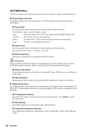
... Sets the system date. The format is not displayed, turn off computer and re-check SATA/ M.2 cable and power cable connections of the device and motherboard. ▶▶System Information Shows detailed system information, including CPU type, BIOS version, and Memory (read only). ▶▶DMI Information Shows system information, desktop...
... Sets the system date. The format is not displayed, turn off computer and re-check SATA/ M.2 cable and power cable connections of the device and motherboard. ▶▶System Information Shows detailed system information, including CPU type, BIOS version, and Memory (read only). ▶▶DMI Information Shows system information, desktop...
User Manual
Page 66
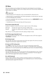
... [Disabled] Please enable A-XMP or select a profile of memory module for CPU ratio. User can only be available when the installed processor, memory modules and motherboard support this function is not guaranteed. Please note that support this function. 66 UEFI BIOS The system may overclock the CPU by adjusting this function...
... [Disabled] Please enable A-XMP or select a profile of memory module for CPU ratio. User can only be available when the installed processor, memory modules and motherboard support this function is not guaranteed. Please note that support this function. 66 UEFI BIOS The system may overclock the CPU by adjusting this function...
User Manual
Page 69
... enter the flash mode. 3. And then follow the steps below to perform the BIOS update process. 5. Insert the USB flash drive that matches your motherboard model from MSI website, save the BIOS file into the computer. 2. Select a BIOS file to update BIOS. 1. The system will enter the flash mode and a file selection...
... enter the flash mode. 3. And then follow the steps below to perform the BIOS update process. 5. Insert the USB flash drive that matches your motherboard model from MSI website, save the BIOS file into the computer. 2. Select a BIOS file to update BIOS. 1. The system will enter the flash mode and a file selection...


