User Manual
Page 1
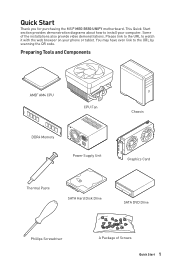
... Components AMD® AM4 CPU CPU Fan DDR4 Memory Power Supply Unit Chassis Graphics Card Thermal Paste SATA Hard Disk Drive SATA DVD Drive Phillips Screwdriver A Package of the installations also provide video demonstrations. Some of Screws Quick Start 1 Please link to the URL to watch it with the web browser on your computer. This Quick Start section provides demonstration diagrams about how to the URL by scanning the QR code. Quick Start Thank...
... Components AMD® AM4 CPU CPU Fan DDR4 Memory Power Supply Unit Chassis Graphics Card Thermal Paste SATA Hard Disk Drive SATA DVD Drive Phillips Screwdriver A Package of the installations also provide video demonstrations. Some of Screws Quick Start 1 Please link to the URL to watch it with the web browser on your computer. This Quick Start section provides demonstration diagrams about how to the URL by scanning the QR code. Quick Start Thank...
User Manual
Page 13
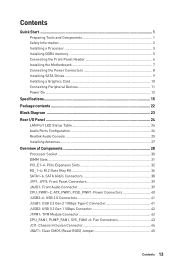
...Quick Start...1 Preparing Tools and Components 1 Safety Information 2 Installing a Processor 3 Installing DDR4 memory 5 Connecting the Front Panel Header 6 Installing the Motherboard 7 Connecting the Power Connectors 8 Installing SATA Drives 9 Installing a Graphics Card 10 Connecting Peripheral Devices 11 Power On...12 Specifications...15 Package contents 22 Block Diagram ...23 Rear I/O Panel...24 LAN Port LED Status Table 24 Audio Ports Configuration 24 Realtek Audio Console 25 Installing Antennas 27 Overview of Components 28 Processor Socket 30 DIMM Slots...31 PCI_E1~4: PCIe...
...Quick Start...1 Preparing Tools and Components 1 Safety Information 2 Installing a Processor 3 Installing DDR4 memory 5 Connecting the Front Panel Header 6 Installing the Motherboard 7 Connecting the Power Connectors 8 Installing SATA Drives 9 Installing a Graphics Card 10 Connecting Peripheral Devices 11 Power On...12 Specifications...15 Package contents 22 Block Diagram ...23 Rear I/O Panel...24 LAN Port LED Status Table 24 Audio Ports Configuration 24 Realtek Audio Console 25 Installing Antennas 27 Overview of Components 28 Processor Socket 30 DIMM Slots...31 PCI_E1~4: PCIe...
User Manual
Page 14
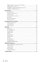
...RGB LED connectors 47 JCORSAIR1: CORSAIR Connector 48 Onboard LEDs...49 EZ Debug LED...49 LED_SW1: EZ LED Control 49 Debug Code LED...49 Hexadecimal Character Table 50 Boot Phases...50 Debug Code LED Table 50 ACPI States Codes 54 Installing OS, Drivers & Utilities 55 Installing Windows® 10 55 Installing Drivers 55 Installing Utilities 55 UEFI BIOS...56 BIOS Setup...57 Entering BIOS Setup 57 Resetting BIOS...58 Updating BIOS...58 EZ Mode...60 Advanced Mode ...63 SETTINGS Menu...64 OC Menu...66 M-FLASH Menu...69 OC PROFILE Menu 70 HARDWARE MONITOR Menu 71 AMD RAID Configuration...
...RGB LED connectors 47 JCORSAIR1: CORSAIR Connector 48 Onboard LEDs...49 EZ Debug LED...49 LED_SW1: EZ LED Control 49 Debug Code LED...49 Hexadecimal Character Table 50 Boot Phases...50 Debug Code LED Table 50 ACPI States Codes 54 Installing OS, Drivers & Utilities 55 Installing Windows® 10 55 Installing Drivers 55 Installing Utilities 55 UEFI BIOS...56 BIOS Setup...57 Entering BIOS Setup 57 Resetting BIOS...58 Updating BIOS...58 EZ Mode...60 Advanced Mode ...63 SETTINGS Menu...64 OC Menu...66 M-FLASH Menu...69 OC PROFILE Menu 70 HARDWARE MONITOR Menu 71 AMD RAID Configuration...
User Manual
Page 29
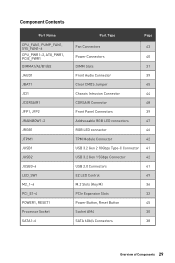
...PCI_E1~4 POWER1, RESET1 Processor Socket SATA1~6 Port Type Page Fan Connectors 43 Power Connectors 40 DIMM Slots 31 Front Audio Connector 39 Clear CMOS Jumper 45 Chassis Intrusion Connector 44 CORSAIR Connector 48 Front Panel Connectors 39 Addressable RGB LED connectors 47 RGB LED connector 46 TPM Module Connector 42 USB 3.2 Gen 2 10Gbps Type-C Connector 41 USB 3.2 Gen 1 5Gbps Connector 42 USB 2.0 Connectors 41 EZ LED Control 49 M.2 Slots (Key M) 36 PCIe Expansion Slots 32 Power Button, Reset Button 45 Socket AM4 30 SATA 6Gb/s Connectors 38 Overview of...
...PCI_E1~4 POWER1, RESET1 Processor Socket SATA1~6 Port Type Page Fan Connectors 43 Power Connectors 40 DIMM Slots 31 Front Audio Connector 39 Clear CMOS Jumper 45 Chassis Intrusion Connector 44 CORSAIR Connector 48 Front Panel Connectors 39 Addressable RGB LED connectors 47 RGB LED connector 46 TPM Module Connector 42 USB 3.2 Gen 2 10Gbps Type-C Connector 41 USB 3.2 Gen 1 5Gbps Connector 42 USB 2.0 Connectors 41 EZ LED Control 49 M.2 Slots (Key M) 36 PCIe Expansion Slots 32 Power Button, Reset Button 45 Socket AM4 30 SATA 6Gb/s Connectors 38 Overview of...
User Manual
Page 47
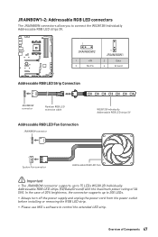
... LED Strip Connection 1 +5V D JRAINBOW connector Rainbow RGB LED extension cable Addressable RGB LED Fan Connection JRAINBOW connector 1 WS2812B Individually Addressable RGB LED strips 5V 1 System Fan connector Addressable RGB LED Fan ⚠⚠Important ∙∙The JRAINBOW connector supports up to 200 LEDs. ∙∙Always turn off the power supply and unplug the power cord from the power outlet before installing or removing the RGB LED strip. ∙∙Please use MSI's software to 75 LEDs...
... LED Strip Connection 1 +5V D JRAINBOW connector Rainbow RGB LED extension cable Addressable RGB LED Fan Connection JRAINBOW connector 1 WS2812B Individually Addressable RGB LED strips 5V 1 System Fan connector Addressable RGB LED Fan ⚠⚠Important ∙∙The JRAINBOW connector supports up to 200 LEDs. ∙∙Always turn off the power supply and unplug the power cord from the power outlet before installing or removing the RGB LED strip. ∙∙Please use MSI's software to 75 LEDs...
User Manual
Page 50
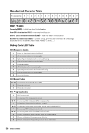
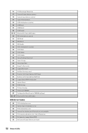
... a bootable device (CD/DVD, HDD, USB, Network, Shell, ...) Debug Code LED Table SEC Progress Codes 01 Power on. Programming memory timing information 50 Onboard LEDs initial low-level initialization Pre-EFI Initialization (PEI) - Serial Presence Detect (SPD) data reading 2C Memory initialization. Memory presence detection 2D Memory initialization. memory initialization Driver Execution Environment (DXE) - Hexadecimal Character Table Hexadecimal 0 1 2 3 4 5 6 7 8 9 A B C D E F Debug Code LED display 0123456789ABCDEF Boot Phases Security (SEC) - Reset type detection (soft/hard) 02 AP...
... a bootable device (CD/DVD, HDD, USB, Network, Shell, ...) Debug Code LED Table SEC Progress Codes 01 Power on. Programming memory timing information 50 Onboard LEDs initial low-level initialization Pre-EFI Initialization (PEI) - Serial Presence Detect (SPD) data reading 2C Memory initialization. Memory presence detection 2D Memory initialization. memory initialization Driver Execution Environment (DXE) - Hexadecimal Character Table Hexadecimal 0 1 2 3 4 5 6 7 8 9 A B C D E F Debug Code LED display 0123456789ABCDEF Boot Phases Security (SEC) - Reset type detection (soft/hard) 02 AP...
User Manual
Page 51
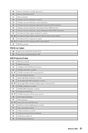
Boot Strap Processor (BSP) selection 36 CPU post-memory initialization. Application Processor(s) (AP) initialization 35 CPU post-memory initialization. Cache initialization 34 CPU post-memory initialization. 2E Memory initialization. Configuring memory 2F Memory initialization (other) 31 Memory Installed 32 CPU post-memory initialization is started 33 CPU post-memory initialization. System Management Mode (SMM) initialization 37 Post-Memory System Agent initialization is started 38 - 3A Post-Memory System Agent initialization (System Agent module specific) 3B Post-Memory PCH ...
Boot Strap Processor (BSP) selection 36 CPU post-memory initialization. Application Processor(s) (AP) initialization 35 CPU post-memory initialization. Cache initialization 34 CPU post-memory initialization. 2E Memory initialization. Configuring memory 2F Memory initialization (other) 31 Memory Installed 32 CPU post-memory initialization is started 33 CPU post-memory initialization. System Management Mode (SMM) initialization 37 Post-Memory System Agent initialization is started 38 - 3A Post-Memory System Agent initialization (System Agent module specific) 3B Post-Memory PCH ...
User Manual
Page 52
... Set Virtual Address MAP End B2 Legacy Option ROM Initialization B3 System Reset B4 USB hot plug B5 PCI bus hot plug B6 Clean-up of NVRAM B7 Configuration Reset (reset of Resources D5 No Space for Legacy Option ROM D6 No Console Output Devices are not available D4 PCI resource allocation error. BF Reserved for future AMI codes A0 IDE initialization is started A1 IDE Reset A2 IDE Detect A3 IDE Enable A4 SCSI initialization is started 9B USB Reset...
... Set Virtual Address MAP End B2 Legacy Option ROM Initialization B3 System Reset B4 USB hot plug B5 PCI bus hot plug B6 Clean-up of NVRAM B7 Configuration Reset (reset of Resources D5 No Space for Legacy Option ROM D6 No Console Output Devices are not available D4 PCI resource allocation error. BF Reserved for future AMI codes A0 IDE initialization is started A1 IDE Reset A2 IDE Detect A3 IDE Enable A4 SCSI initialization is started 9B USB Reset...
User Manual
Page 55
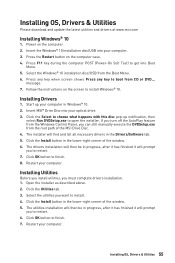
... window. 5. Installing Utilities Before you install utilities, you want to install Windows® 10. Power on the screen to install. 4. Press the Restart button on the computer case. 4. Press any key when screen shows Press any key to restart. 6. If you turn off the AutoPlay feature from the Windows Control Panel, you to boot from the Boot Menu. 6. The drivers installation will then be in progress, after it has finished it will find and list...
... window. 5. Installing Utilities Before you install utilities, you want to install Windows® 10. Power on the screen to install. 4. Press the Restart button on the computer case. 4. Press any key when screen shows Press any key to restart. 6. If you turn off the AutoPlay feature from the Windows Control Panel, you to boot from the Boot Menu. 6. The drivers installation will then be in progress, after it has finished it will find and list...
User Manual
Page 58
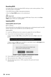
Press to activate M-Flash for resetting BIOS. Insert the USB flash drive that matches your motherboard model from MSI website. And then save the BIOS file into the USB port. 2. Select a BIOS file to enter BIOS. Please refer to the Clear CMOS jumper section for BIOS update. ▪▪Reboot and press Del key during POST and click on Yes to start recovering BIOS. 5. Updating BIOS: 1. After the flashing process is off before clearing CMOS data. Click the M-FLASH button and click on the...
Press to activate M-Flash for resetting BIOS. Insert the USB flash drive that matches your motherboard model from MSI website. And then save the BIOS file into the USB port. 2. Select a BIOS file to enter BIOS. Please refer to the Clear CMOS jumper section for BIOS update. ▪▪Reboot and press Del key during POST and click on Yes to start recovering BIOS. 5. Updating BIOS: 1. After the flashing process is off before clearing CMOS data. Click the M-FLASH button and click on the...
User Manual
Page 59
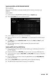
... to flash BIOS, and the LED starts flashing. 6. Click on Download icon to download and install the latest BIOS file. 5. Select the BIOS file and click on Scan button to the root of your motherboard model from the MSI® website. 2. Updating BIOS with MSI DRAGON CENTER Before updating: Make sure the LAN driver is already installed and the internet connection is set properly. Plug the USB flash drive that matches your USB flash drive. 3. Press the Flash BIOS Button to Support page. 2. After the flashing process...
... to flash BIOS, and the LED starts flashing. 6. Click on Download icon to download and install the latest BIOS file. 5. Select the BIOS file and click on Scan button to the root of your motherboard model from the MSI® website. 2. Updating BIOS with MSI DRAGON CENTER Before updating: Make sure the LAN driver is already installed and the internet connection is set properly. Plug the USB flash drive that matches your USB flash drive. 3. Press the Flash BIOS Button to Support page. 2. After the flashing process...
User Manual
Page 61
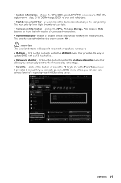
... this button to enter the Hardware Monitor menu that provides the way to change the boot priority. The boot priority from high to low is enabled when the button shows ON . ⚠⚠Important The function buttons will vary with a USB flash drive. ∙∙ Hardware Monitor - The function is left to manually control the fan speed by clicking on the CPU, Memory, Storage, Fan Info and Help buttons to show the Favorites window. It...
... this button to enter the Hardware Monitor menu that provides the way to change the boot priority. The boot priority from high to low is enabled when the button shows ON . ⚠⚠Important The function buttons will vary with a USB flash drive. ∙∙ Hardware Monitor - The function is left to manually control the fan speed by clicking on the CPU, Memory, Storage, Fan Info and Help buttons to show the Favorites window. It...

User Manual
Page 63
... a USB flash drive. ▪▪OC PROFILE - UEFI BIOS 63 provides the information of system. ▪▪BOARD EXPLORER - provides BIOS setting items and information to specify the parameters for chipset and boot devices. ▪▪OC - Advanced Mode Press Setup Mode switch or F7 function key can switch between EZ Mode and Advanced Mode in BIOS setup. allows you to set the speeds of fans and monitor voltages of installed devices on this motherboard. ∙∙ Menu display - the following options...
... a USB flash drive. ▪▪OC PROFILE - UEFI BIOS 63 provides the information of system. ▪▪BOARD EXPLORER - provides BIOS setting items and information to specify the parameters for chipset and boot devices. ▪▪OC - Advanced Mode Press Setup Mode switch or F7 function key can switch between EZ Mode and Advanced Mode in BIOS setup. allows you to set the speeds of fans and monitor voltages of installed devices on this motherboard. ∙∙ Menu display - the following options...
User Manual
Page 64
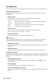
...-check SATA/ M.2 cable and power cable connections of the device and motherboard. ▶▶System Information Shows detailed system information, including CPU type, BIOS version, and Memory (read only). ▶▶DMI Information Shows system information, desktop board information and chassis information. ▶▶Advanced sub-menu The Advanced sub-menu allows you to set the parameters and behaviors of PCIe, ACPI, integrated peripherals, integrated graphics, USB, power management and Windows . ▶▶PCI Subsystem Settings Sets PCI, PCI express...
...-check SATA/ M.2 cable and power cable connections of the device and motherboard. ▶▶System Information Shows detailed system information, including CPU type, BIOS version, and Memory (read only). ▶▶DMI Information Shows system information, desktop board information and chassis information. ▶▶Advanced sub-menu The Advanced sub-menu allows you to set the parameters and behaviors of PCIe, ACPI, integrated peripherals, integrated graphics, USB, power management and Windows . ▶▶PCI Subsystem Settings Sets PCI, PCI express...
User Manual
Page 65
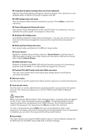
... BIOS setup utility with IGP. ▶▶USB Configuration sub-menu Sets the onboard USB controller and device function. To clear a set password, press Enter when you to set the secure boot and control key management to set the system boot states and the sequence of ErP and AC Power Loss behaviors. The password typed now will confirm the password is the best way to set password from a SSD. A message will replace any previous set the administrator password and the user password...
... BIOS setup utility with IGP. ▶▶USB Configuration sub-menu Sets the onboard USB controller and device function. To clear a set password, press Enter when you to set the secure boot and control key management to set the system boot states and the sequence of ErP and AC Power Loss behaviors. The password typed now will confirm the password is the best way to set password from a SSD. A message will replace any previous set the administrator password and the user password...
User Manual
Page 66
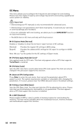
... mode. ▶▶CPU Ratio Apply Mode [All Core]* Sets applied mode for CPU ratio. OC Menu This menu allows you to use * as the symbol for the OC settings of memory module for overclocking the memory. You may overclock the CPU by adjusting this function. 66 UEFI BIOS Please note that support this function. ▶▶Advanced CPU Configuration Press Enter to configure the frequencies and voltages for overclocking. This item can set the parameters about CPU power...
... mode. ▶▶CPU Ratio Apply Mode [All Core]* Sets applied mode for CPU ratio. OC Menu This menu allows you to use * as the symbol for the OC settings of memory module for overclocking the memory. You may overclock the CPU by adjusting this function. 66 UEFI BIOS Please note that support this function. ▶▶Advanced CPU Configuration Press Enter to configure the frequencies and voltages for overclocking. This item can set the parameters about CPU power...
User Manual
Page 67
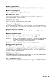
... about voltage/ current/ temputure for CPU. ▶▶CPU Voltages control [Auto] These options allows you can set it occurs, please clear the CMOS data and restore the default settings. (Refer to the Clear CMOS jumper section to clear the CMOS data, and enter the BIOS to load the default settings.) ▶▶DigitALL Power sub-menu Press Enter to enter the sub-menu. System will be available when the installed processor supports this function. ▶▶Memory Failure Retry [Enabled] Enables or disables the...
... about voltage/ current/ temputure for CPU. ▶▶CPU Voltages control [Auto] These options allows you can set it occurs, please clear the CMOS data and restore the default settings. (Refer to the Clear CMOS jumper section to clear the CMOS data, and enter the BIOS to load the default settings.) ▶▶DigitALL Power sub-menu Press Enter to enter the sub-menu. System will be available when the installed processor supports this function. ▶▶Memory Failure Retry [Enabled] Enables or disables the...
User Manual
Page 69
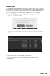
Please download the latest BIOS file that contains the update file into your motherboard model from MSI website, save the BIOS file into the computer. 2. The system will enter the flash mode and a file selection menu will reboot automatically. Select a BIOS file to reboot and enter the flash mode. 3. UEFI BIOS 69 Insert the USB flash drive that matches your USB flash drive. Click on M-FLASH tab, a demand message will be prompted. After the flashing process is 100% completed, the system...
Please download the latest BIOS file that contains the update file into your motherboard model from MSI website, save the BIOS file into the computer. 2. The system will enter the flash mode and a file selection menu will reboot automatically. Select a BIOS file to reboot and enter the flash mode. 3. UEFI BIOS 69 Insert the USB flash drive that matches your USB flash drive. Click on M-FLASH tab, a demand message will be prompted. After the flashing process is 100% completed, the system...
User Manual
Page 77
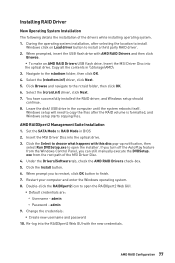
... system installation, after the RAID volume is formatted, and Windows setup starts copying files. Leave the disk/ USB drive in \\Storage\AMD\ 3. Click the Install button. 6. When prompted, insert the USB flash drive with the new credentials. Navigate to RAID Mode in BIOS 2. Set the SATA Mode to the rcbottom folder, then click OK. 4. admin 9. Re-log into the RAIDXpert2 Web GUI with AMD RAID Drivers and then click Browse. ▪▪To make an AMD RAID Drivers USB flash drive...
... system installation, after the RAID volume is formatted, and Windows setup starts copying files. Leave the disk/ USB drive in \\Storage\AMD\ 3. Click the Install button. 6. When prompted, insert the USB flash drive with the new credentials. Navigate to RAID Mode in BIOS 2. Set the SATA Mode to the rcbottom folder, then click OK. 4. admin 9. Re-log into the RAIDXpert2 Web GUI with AMD RAID Drivers and then click Browse. ▪▪To make an AMD RAID Drivers USB flash drive...
User Manual
Page 78
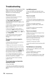
...;Verify the Clear CMOS jumper JBAT1 is no audio ∙∙Adjust the volume. ∙∙Connect the speakers/headphones to lose all customized settings in the BIOS. The USB device is not working ∙∙Make sure your USB drive driver has been installed. ∙∙Verify if USB device is turned on. ∙∙Select different inputs on the monitor. ∙∙If 3 long beeps are heard, remove all ATX power connectors like...
...;Verify the Clear CMOS jumper JBAT1 is no audio ∙∙Adjust the volume. ∙∙Connect the speakers/headphones to lose all customized settings in the BIOS. The USB device is not working ∙∙Make sure your USB drive driver has been installed. ∙∙Verify if USB device is turned on. ∙∙Select different inputs on the monitor. ∙∙If 3 long beeps are heard, remove all ATX power connectors like...


