
User Manual
Page 11
... CPU_FAN1, PUMP_FAN1, SYS_FAN1~5: Fan Connectors 34 JCOM1: Serial Port Connector 35 JCI1: Chassis Intrusion Connector 35 JTPM1: TPM Module Connector 36 JBAT1: Clear CMOS (Reset BIOS) Jumper 36 JRGB1~2, JRAINBOW1: RGB LED connectors 37 Onboard LEDs ...38 EZ Debug LED...38 Contents 11
... CPU_FAN1, PUMP_FAN1, SYS_FAN1~5: Fan Connectors 34 JCOM1: Serial Port Connector 35 JCI1: Chassis Intrusion Connector 35 JTPM1: TPM Module Connector 36 JBAT1: Clear CMOS (Reset BIOS) Jumper 36 JRGB1~2, JRAINBOW1: RGB LED connectors 37 Onboard LEDs ...38 EZ Debug LED...38 Contents 11

User Manual
Page 12
... 39 Installing Windows® 10 39 Installing Drivers 39 Installing Utilities 39 MYSTIC LIGHT...40 Device LED effect control screen 40 BIOS Setup ...43 Entering BIOS Setup 43 Resetting BIOS...44 Updating BIOS...44 EZ Mode ...45 Advanced Mode ...47 SETTINGS...48 Advanced...48 Boot...55 Security ...56 Save & Exit...57 OC...58 M-FLASH...
... 39 Installing Windows® 10 39 Installing Drivers 39 Installing Utilities 39 MYSTIC LIGHT...40 Device LED effect control screen 40 BIOS Setup ...43 Entering BIOS Setup 43 Resetting BIOS...44 Updating BIOS...44 EZ Mode ...45 Advanced Mode ...47 SETTINGS...48 Advanced...48 Boot...55 Security ...56 Save & Exit...57 OC...58 M-FLASH...
User Manual
Page 13
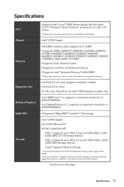
...bandwidth. Please refer to page 29 for details. ** Before using Intel® Optane™ memory modules, please ensure that you have updated the drivers and BIOS to 64GB* y Supports DDR4 4400(OC)/ 4300(OC)/ 4266(OC)/ 4200(OC)/ 4133(OC)/ 4000(OC)/ 3866(OC)/ 3733(OC)/ 3600(OC)/...Dual-Channel mode y Supports non-ECC, un-buffered memory y Supports Intel® Extreme Memory Profile (XMP) * Please refer www.msi.com for more compatibility information. Intel® Z390 Chipset y 4x DDR4 memory slots, support up to www.intel.com for more information on next page Specifications 13 Continued...
...bandwidth. Please refer to page 29 for details. ** Before using Intel® Optane™ memory modules, please ensure that you have updated the drivers and BIOS to 64GB* y Supports DDR4 4400(OC)/ 4300(OC)/ 4266(OC)/ 4200(OC)/ 4133(OC)/ 4000(OC)/ 3866(OC)/ 3733(OC)/ 3600(OC)/...Dual-Channel mode y Supports non-ECC, un-buffered memory y Supports Intel® Extreme Memory Profile (XMP) * Please refer www.msi.com for more compatibility information. Intel® Z390 Chipset y 4x DDR4 memory slots, support up to www.intel.com for more information on next page Specifications 13 Continued...
User Manual
Page 15
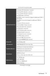
... Monitor y CPU/System temperature detection y CPU/System fan speed detection y CPU/System fan speed control Form Factor y ATX Form Factor y 9.6 in . (24.3 cm x 30.4 cm) BIOS Features y 1x 128 Mb flash y UEFI AMI BIOS y ACPI 6.1, SMBIOS 2.8 y Multi-language Continued on next page Specifications 15
... Monitor y CPU/System temperature detection y CPU/System fan speed detection y CPU/System fan speed control Form Factor y ATX Form Factor y 9.6 in . (24.3 cm x 30.4 cm) BIOS Features y 1x 128 Mb flash y UEFI AMI BIOS y ACPI 6.1, SMBIOS 2.8 y Multi-language Continued on next page Specifications 15
User Manual
Page 17
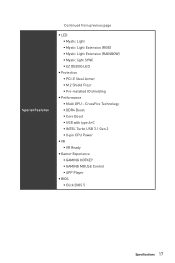
...; INTEL Turbo USB 3.1 Gen 2 ƒ 8-pin CPU Power y VR ƒ VR Ready y Gamer Experience ƒ GAMING HOTKEY ƒ GAMING MOUSE Control ƒ APP Player y BIOS ƒ Click BIOS 5 Specifications 17 Special Features Continued from previous page y LED ƒ Mystic Light ƒ Mystic Light Extension (RGB) ƒ Mystic Light Extension (RAINBOW...
...; INTEL Turbo USB 3.1 Gen 2 ƒ 8-pin CPU Power y VR ƒ VR Ready y Gamer Experience ƒ GAMING HOTKEY ƒ GAMING MOUSE Control ƒ APP Player y BIOS ƒ Click BIOS 5 Specifications 17 Special Features Continued from previous page y LED ƒ Mystic Light ƒ Mystic Light Extension (RGB) ƒ Mystic Light Extension (RAINBOW...
User Manual
Page 24
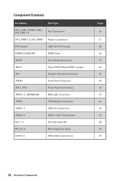
...~5 Fan Connectors CPU_PWR1~2, ATX_PWR1 Power Connectors CPU Socket LGA1151 CPU Socket DIMMA1/A2/B1/B2 DIMM Slots JAUD1 Front Audio Connector JBAT1 Clear CMOS (Reset BIOS) Jumper JCI1 Chassis Intrusion Connector JCOM1 Serial Port Connector JFP1, JFP2 Front Panel Connectors JRGB1~2, JRAINBOW1 RGB LED connectors JTPM1 TPM Module Connector JUSB1~2 USB...
...~5 Fan Connectors CPU_PWR1~2, ATX_PWR1 Power Connectors CPU Socket LGA1151 CPU Socket DIMMA1/A2/B1/B2 DIMM Slots JAUD1 Front Audio Connector JBAT1 Clear CMOS (Reset BIOS) Jumper JCI1 Chassis Intrusion Connector JCOM1 Serial Port Connector JFP1, JFP2 Front Panel Connectors JRGB1~2, JRAINBOW1 RGB LED connectors JTPM1 TPM Module Connector JUSB1~2 USB...
User Manual
Page 26
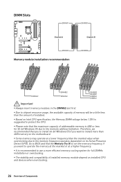
... memory is 4GB or less for full DIMMs installation or overclocking. y Please note that you to install 64-bit Windows OS if you want to BIOS and find the Memory Try It! y Some memory may operate at a higher frequency. y It is suggested to the memory frequency operates dependent on installed CPU...
... memory is 4GB or less for full DIMMs installation or overclocking. y Please note that you to install 64-bit Windows OS if you want to BIOS and find the Memory Try It! y Some memory may operate at a higher frequency. y It is suggested to the memory frequency operates dependent on installed CPU...
User Manual
Page 34
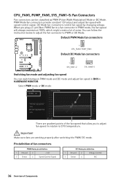
...) Mode or DC Mode. CPU_FAN1, PUMP_FAN1, SYS_FAN1~5: Fan Connectors Fan connectors can follow the instruction below to adjust the fan connector to a fan connector in BIOS > HARDWARE MONITOR. DC Mode fan connectors control fan speed by changing voltage. Important Make sure fans are gradient points of Components Pin definition of fan...
...) Mode or DC Mode. CPU_FAN1, PUMP_FAN1, SYS_FAN1~5: Fan Connectors Fan connectors can follow the instruction below to adjust the fan connector to a fan connector in BIOS > HARDWARE MONITOR. DC Mode fan connectors control fan speed by changing voltage. Important Make sure fans are gradient points of Components Pin definition of fan...
User Manual
Page 35
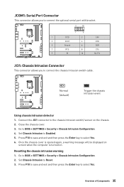
... intrusion switch/ sensor on . Overview of Components 35 Go to select Yes. Press F10 to save and exit and then press the Enter key to BIOS > SETTINGS > Security > Chassis Intrusion Configuration. 2. Connect the JCI1 connector to select Yes. 6. Set Chassis Intrusion to...
... intrusion switch/ sensor on . Overview of Components 35 Go to select Yes. Press F10 to save and exit and then press the Enter key to BIOS > SETTINGS > Security > Chassis Intrusion Configuration. 2. Connect the JCI1 connector to select Yes. 6. Set Chassis Intrusion to...
User Manual
Page 36
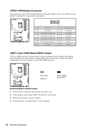
... 8 5V Power 9 LPC address & data pin2 10 No Pin 11 LPC address & data pin3 12 Ground 13 LPC Frame 14 Ground JBAT1: Clear CMOS (Reset BIOS) Jumper There is CMOS memory onboard that is for about 5-10 seconds. 3. Keep Data (default) Clear CMOS/ Reset...
... 8 5V Power 9 LPC address & data pin2 10 No Pin 11 LPC address & data pin3 12 Ground 13 LPC Frame 14 Ground JBAT1: Clear CMOS (Reset BIOS) Jumper There is CMOS memory onboard that is for about 5-10 seconds. 3. Keep Data (default) Clear CMOS/ Reset...
User Manual
Page 43
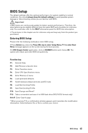
... or failure booting unless you press F10, a confirmation window appears and it to confirm your choice. Important y BIOS items are familiar with BIOS. BIOS Setup The default settings offer the optimal performance for system stability in this chapter are for reference only and may be...y The pictures in normal conditions. Ctrl+F: Enter Search page * When you are continuously update for better system performance. BIOS Setup 43 You should be slightly different from the product you purchased. y In MSI Dragon Center application, click on the screen during the boot process.
... or failure booting unless you press F10, a confirmation window appears and it to confirm your choice. Important y BIOS items are familiar with BIOS. BIOS Setup The default settings offer the optimal performance for system stability in this chapter are for reference only and may be...y The pictures in normal conditions. Ctrl+F: Enter Search page * When you are continuously update for better system performance. BIOS Setup 43 You should be slightly different from the product you purchased. y In MSI Dragon Center application, click on the screen during the boot process.
User Manual
Page 44
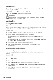
... is 100% completed, the system will reboot automatically. Insert the USB flash drive that matches your motherboard model from MSI website. Select a BIOS file to reboot the system. 3. Important Be sure the computer is 100% completed, the system will restart automatically. 44... that contains the update file into the USB flash drive. Install and launch MSI LIVE UPDATE 6. 2. Select BIOS Update. 3. Updating BIOS: 1. Please refer to download and install the latest BIOS file. 5. And then save the BIOS file into the USB port. 2. Click on Yes to reboot the system. ƒ ...
... is 100% completed, the system will reboot automatically. Insert the USB flash drive that matches your motherboard model from MSI website. Select a BIOS file to reboot the system. 3. Important Be sure the computer is 100% completed, the system will restart automatically. 44... that contains the update file into the USB flash drive. Install and launch MSI LIVE UPDATE 6. 2. Select BIOS Update. 3. Updating BIOS: 1. Please refer to download and install the latest BIOS file. 5. And then save the BIOS file into the USB port. 2. Click on Yes to reboot the system. ƒ ...
User Manual
Page 45
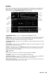
...only). Move the mouse over a blank space and right click the mouse to select the X.M.P. y Setup Mode switch - y Language - y System information - BIOS Setup 45 This switch will show. y Search - The boot priority from high to low is installed. click on this tab or the F12 key to... the X.M.P. (Extreme Memory Profile). shows the CPU/ DDR speed, CPU/ MB temperature, MB/ CPU type, memory size, CPU/ DDR voltage, BIOS version and build date. profile. Important In search page, only the F6, F10 and F12 function keys are available. XMP switch Setup Mode switch ...
...only). Move the mouse over a blank space and right click the mouse to select the X.M.P. y Setup Mode switch - y Language - y System information - BIOS Setup 45 This switch will show. y Search - The boot priority from high to low is installed. click on this tab or the F12 key to... the X.M.P. (Extreme Memory Profile). shows the CPU/ DDR speed, CPU/ MB temperature, MB/ CPU type, memory size, CPU/ DDR voltage, BIOS version and build date. profile. Important In search page, only the F6, F10 and F12 function keys are available. XMP switch Setup Mode switch ...
User Manual
Page 46
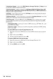
...the CPU, Memory, Storage, Fan Info and Help buttons on OK. ƒ To delete a BIOS item from favorite page 1. click on search page. 2. y Function buttons - It allows you to create personal BIOS menu where you to display related information. Choose a favorite page and click on left side to... enable or disable the LAN Option ROM, M.2/ Optane Genie, HD audio controller, AHCI/ RAID, CPU Fan Fail Warning Control and BIOS Log Review by percentage. y M-Flash - click on favorite page (Favorite 1~5) 2. Choose Delete and click on their respective button. y Information display - ...
...the CPU, Memory, Storage, Fan Info and Help buttons on OK. ƒ To delete a BIOS item from favorite page 1. click on search page. 2. y Function buttons - It allows you to create personal BIOS menu where you to display related information. Choose a favorite page and click on left side to... enable or disable the LAN Option ROM, M.2/ Optane Genie, HD audio controller, AHCI/ RAID, CPU Fan Fail Warning Control and BIOS Log Review by percentage. y M-Flash - click on favorite page (Favorite 1~5) 2. Choose Delete and click on their respective button. y Information display - ...
User Manual
Page 47
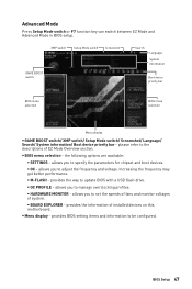
...provides the way to adjust the frequency and voltage. allows you to update BIOS with a USB flash drive. ƒ OC PROFILE - BIOS Setup 47 y BIOS menu selection - y Menu display - provides BIOS setting items and information to set the speeds of fans and monitor voltages of...ƒ BOARD EXPLORER - XMP switch Setup Mode switch Screenshot GAME BOOST switch Search Language System information Boot device priority bar BIOS menu selection BIOS menu selection Menu display y GAME BOOST switch/ XMP switch/ Setup Mode switch/ Screenshot/ Language/ Search/ System information/ ...
...provides the way to adjust the frequency and voltage. allows you to update BIOS with a USB flash drive. ƒ OC PROFILE - BIOS Setup 47 y BIOS menu selection - y Menu display - provides BIOS setting items and information to set the speeds of fans and monitor voltages of...ƒ BOARD EXPLORER - XMP switch Setup Mode switch Screenshot GAME BOOST switch Search Language System information Boot device priority bar BIOS menu selection BIOS menu selection Menu display y GAME BOOST switch/ XMP switch/ Setup Mode switch/ Screenshot/ Language/ Search/ System information/ ...
User Manual
Page 48
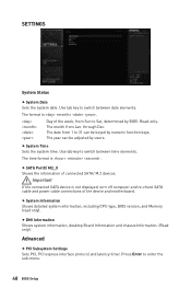
...time elements. The date from 1 to Sat, determined by numeric function keys. The month from Sun to 31 can be keyed by BIOS. The time format is not displayed, turn off computer and re-check SATA cable and power cable connections of the device and motherboard.... Enter to switch between date elements. f System Information Shows detailed system information, including CPU type, BIOS version, and Memory (read only). through Dec. Use tab key to enter the sub-menu. 48 BIOS Setup Important If the connected SATA device is . Day of connected SATA/ M.2 devices. f System...
...time elements. The date from 1 to Sat, determined by numeric function keys. The month from Sun to 31 can be keyed by BIOS. The time format is not displayed, turn off computer and re-check SATA cable and power cable connections of the device and motherboard.... Enter to switch between date elements. f System Information Shows detailed system information, including CPU type, BIOS version, and Memory (read only). through Dec. Use tab key to enter the sub-menu. 48 BIOS Setup Important If the connected SATA device is . Day of connected SATA/ M.2 devices. f System...
User Manual
Page 49
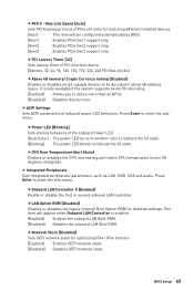
...Controller X [Enabled] Enable or disable the first or second onboard LAN controller. This item will be decoded in above 4G address space. BIOS Setup 49 fPEG X - Press Enter to enter the sub-menu. f Integrated Peripherals Sets integrated peripherals' parameters, such as LAN, HDD, ... 248 PCI Bus clocks] fAbove 4G memory/ Crypto Currency mining [Disabled] Enables or disables 64-bit capable devices to be configured automatically by BIOS. [Gen1] Enables PCIe Gen1 support only. [Gen2] Enables PCIe Gen2 support only. [Gen3] Enables PCIe Gen3 support only. fPCI Latency Timer...
...Controller X [Enabled] Enable or disable the first or second onboard LAN controller. This item will be decoded in above 4G address space. BIOS Setup 49 fPEG X - Press Enter to enter the sub-menu. f Integrated Peripherals Sets integrated peripherals' parameters, such as LAN, HDD, ... 248 PCI Bus clocks] fAbove 4G memory/ Crypto Currency mining [Disabled] Enables or disables 64-bit capable devices to be configured automatically by BIOS. [Gen1] Enables PCIe Gen1 support only. [Gen2] Enables PCIe Gen2 support only. [Gen3] Enables PCIe Gen3 support only. fPCI Latency Timer...
User Manual
Page 50
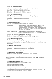
... plug support for the SATA ports. [Disabled] Disables hot plug support for setting up M.2 device. This item will appear when Network Stack is enabled. 50 BIOS Setup fIpv4 PXE Support [Enabled] When Enabled, the system UEFI network stack will support Ipv6 protocol. fM.2/Optane Genie [Disabled] Enables or disables M.2 storage/ Optane...
... plug support for the SATA ports. [Disabled] Disables hot plug support for setting up M.2 device. This item will appear when Network Stack is enabled. 50 BIOS Setup fIpv4 PXE Support [Enabled] When Enabled, the system UEFI network stack will support Ipv6 protocol. fM.2/Optane Genie [Disabled] Enables or disables M.2 storage/ Optane...
User Manual
Page 51
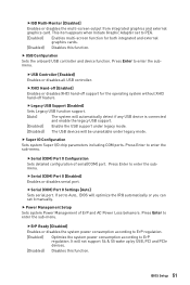
...Enables or disables the system power consumption according to ErP regulation. [Enabled] Optimize the system power consumption according to enter the sub-menu. BIOS Setup 51 fSerial (COM) Port 0 Configuration Sets detailed configuration of ErP and AC Power Loss behaviors. Press Enter to enter...[Enabled] Enable the USB support under legacy mode. fUSB Controller [Enabled] Enables or disables all USB controller. If set to Auto, BIOS will be unavailable under legacy mode. [Disabled] The USB devices will optimize the IRQ automatically or you can set to enter the submenu...
...Enables or disables the system power consumption according to ErP regulation. [Enabled] Optimize the system power consumption according to enter the sub-menu. BIOS Setup 51 fSerial (COM) Port 0 Configuration Sets detailed configuration of ErP and AC Power Loss behaviors. Press Enter to enter...[Enabled] Enable the USB support under legacy mode. fUSB Controller [Enabled] Enables or disables all USB controller. If set to Auto, BIOS will be unavailable under legacy mode. [Disabled] The USB devices will optimize the IRQ automatically or you can set to enter the submenu...
User Manual
Page 52
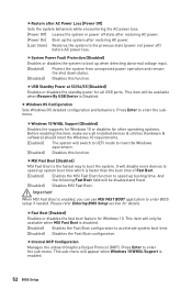
...disable more devices to speed up system boot time which is enabled. 52 BIOS Setup f Windows OS Configuration Sets Windows OS detailed configuration and behaviors. It will be disabled and fixed. [Disabled] Disables MSI Fast Boot. This sub-menu will switch to UEFI mode to the previous ...fInternal GOP Configuration Manages the onboard Graphics Output Protocol (GOP). Important When MSI Fast Boot is the fastest way to enter BIOS setup if needed. fMSI Fast Boot [Disabled] MSI Fast Boot is enabled, you can use MSI FAST BOOT application to boot the system. fRestore after AC Power Loss ...
...disable more devices to speed up system boot time which is enabled. 52 BIOS Setup f Windows OS Configuration Sets Windows OS detailed configuration and behaviors. It will be disabled and fixed. [Disabled] Disables MSI Fast Boot. This sub-menu will switch to UEFI mode to the previous ...fInternal GOP Configuration Manages the onboard Graphics Output Protocol (GOP). Important When MSI Fast Boot is the fastest way to enter BIOS setup if needed. fMSI Fast Boot [Disabled] MSI Fast Boot is enabled, you can use MSI FAST BOOT application to boot the system. fRestore after AC Power Loss ...


