User Manual
Page 13
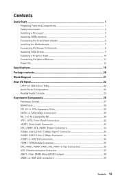
... 34 JUSB1~2: USB 2.0 Connectors 35 JTPM1: TPM Module Connector 35 CPU_FAN1, PUMP_FAN1, SYS_FAN1~6: Fan Connectors 36 JCI1: Chassis Intrusion Connector 37 JBAT1: Clear CMOS (Reset BIOS) Jumper 38 JRGB1~2: RGB LED connectors 39 Contents 13
... 34 JUSB1~2: USB 2.0 Connectors 35 JTPM1: TPM Module Connector 35 CPU_FAN1, PUMP_FAN1, SYS_FAN1~6: Fan Connectors 36 JCI1: Chassis Intrusion Connector 37 JBAT1: Clear CMOS (Reset BIOS) Jumper 38 JRGB1~2: RGB LED connectors 39 Contents 13
User Manual
Page 14
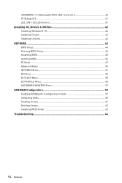
... LED Control 41 Installing OS, Drivers & Utilities 42 Installing Windows® 10 42 Installing Drivers 42 Installing Utilities 42 UEFI BIOS...43 BIOS Setup...44 Entering BIOS Setup 44 Resetting BIOS...45 Updating BIOS...45 EZ Mode ...47 Advanced Mode ...50 SETTINGS Menu 51 OC Menu...53 M-FLASH Menu ...55 OC PROFILE Menu 56 HARDWARE...
... LED Control 41 Installing OS, Drivers & Utilities 42 Installing Windows® 10 42 Installing Drivers 42 Installing Utilities 42 UEFI BIOS...43 BIOS Setup...44 Entering BIOS Setup 44 Resetting BIOS...45 Updating BIOS...45 EZ Mode ...47 Advanced Mode ...50 SETTINGS Menu 51 OC Menu...53 M-FLASH Menu ...55 OC PROFILE Menu 56 HARDWARE...
User Manual
Page 15
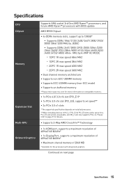
...8729;1x DisplayPort, supports a maximum resolution of 4096x2160 @60Hz* ∙∙Maximum shared memory of 2048 MB * Available for the processor with BIOS update AMD B550 Chipset ∙∙4x DDR4 memory slots, support up to 128GB* ▪▪Supports DDR4 1866/ 2133/ 2400/ 2667/ 2800/ 2933/ ...8729;Supports non-ECC UDIMM memory ∙∙Supports ECC UDIMM memory (non-ECC mode) ∙∙Supports un-buffered memory * Please refer www.msi.com for more information on compatible memory. ∙∙1x PCIe 4.0/ 3.0 x16 slot (PCI_E1)* ∙∙1x PCIe 3.0 x16 slot (PCI_E3...
...8729;1x DisplayPort, supports a maximum resolution of 4096x2160 @60Hz* ∙∙Maximum shared memory of 2048 MB * Available for the processor with BIOS update AMD B550 Chipset ∙∙4x DDR4 memory slots, support up to 128GB* ▪▪Supports DDR4 1866/ 2133/ 2400/ 2667/ 2800/ 2933/ ...8729;Supports non-ECC UDIMM memory ∙∙Supports ECC UDIMM memory (non-ECC mode) ∙∙Supports un-buffered memory * Please refer www.msi.com for more information on compatible memory. ∙∙1x PCIe 4.0/ 3.0 x16 slot (PCI_E1)* ∙∙1x PCIe 3.0 x16 slot (PCI_E3...
User Manual
Page 17
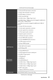
... Clear CMOS jumper LED Features ∙∙1x EZ LED Control switch ∙∙4x EZ Debug LED Back Panel Connectors ∙∙1x Flash BIOS Button ∙∙1x PS/2 keyboard/ mouse combo port ∙∙2x USB 2.0 Type-A ports ∙∙1x Display port ∙∙1x HDMI port...
... Clear CMOS jumper LED Features ∙∙1x EZ LED Control switch ∙∙4x EZ Debug LED Back Panel Connectors ∙∙1x Flash BIOS Button ∙∙1x PS/2 keyboard/ mouse combo port ∙∙2x USB 2.0 Type-A ports ∙∙1x Display port ∙∙1x HDMI port...
User Manual
Page 18
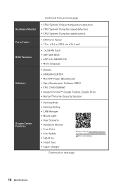
Continued on next page 18 Specifications x 9.6 in . Continued from previous page Hardware Monitor Form Factor BIOS Features Software Dragon Center Features ∙∙CPU/ System/ Chipset temperature detection ∙∙CPU/ System/ Pump fan speed detection...;1x 256 Mb flash ∙∙UEFI AMI BIOS ∙∙ACPI 6.0, SMBIOS 2.8 ∙∙ Multi-language ∙∙ Drivers ∙∙DRAGON CENTER ∙∙MSI APP Player (BlueStacks) ∙∙Open Broadcaster Software (OBS) ∙∙CPU-Z MSI GAMING ∙∙Google Chrome™, Google Toolbar...
Continued on next page 18 Specifications x 9.6 in . Continued from previous page Hardware Monitor Form Factor BIOS Features Software Dragon Center Features ∙∙CPU/ System/ Chipset temperature detection ∙∙CPU/ System/ Pump fan speed detection...;1x 256 Mb flash ∙∙UEFI AMI BIOS ∙∙ACPI 6.0, SMBIOS 2.8 ∙∙ Multi-language ∙∙ Drivers ∙∙DRAGON CENTER ∙∙MSI APP Player (BlueStacks) ∙∙Open Broadcaster Software (OBS) ∙∙CPU-Z MSI GAMING ∙∙Google Chrome™, Google Toolbar...

User Manual
Page 19
... ▪▪PCI-E Steel Armor ▪▪PCI-E Steel Slot ▪▪Pre-installed I/O Shielding ∙∙ Experience ▪▪Dragon Center ▪▪Click BIOS 5 ▪▪Flash BIOS Button Specifications 19
... ▪▪PCI-E Steel Armor ▪▪PCI-E Steel Slot ▪▪Pre-installed I/O Shielding ∙∙ Experience ▪▪Dragon Center ▪▪Click BIOS 5 ▪▪Flash BIOS Button Specifications 19
User Manual
Page 22
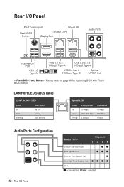
... ● Line-Out/ Front Speaker Out Mic In (●: connected, Blank: empty) Please refer to page 48 for Updating BIOS with Flash BIOS Button. LAN Port LED Status Table Link/ Activity LED Status Off Yellow Blinking Description No link Linked Data activity Speed LED Status ... 100/ 1000 Mbps 2.5 Gbps 10 Mbps 100 Mbps 1 Gbps Audio Ports Configuration 22 Rear I /O Panel PS/2 Combo port 1 Gbps LAN Flash BIOS Button 2.5 Gbps LAN DisplayPort Audio Ports Flash BIOS Port USB 2.0 Type-A USB 3.2 Gen 1 (5Gbps) Type-A USB 3.2 Gen 2 (10Gbps) Type-A USB 3.2 Gen 2 (10Gbps) Type-C ...
... ● Line-Out/ Front Speaker Out Mic In (●: connected, Blank: empty) Please refer to page 48 for Updating BIOS with Flash BIOS Button. LAN Port LED Status Table Link/ Activity LED Status Off Yellow Blinking Description No link Linked Data activity Speed LED Status ... 100/ 1000 Mbps 2.5 Gbps 10 Mbps 100 Mbps 1 Gbps Audio Ports Configuration 22 Rear I /O Panel PS/2 Combo port 1 Gbps LAN Flash BIOS Button 2.5 Gbps LAN DisplayPort Audio Ports Flash BIOS Port USB 2.0 Type-A USB 3.2 Gen 1 (5Gbps) Type-A USB 3.2 Gen 2 (10Gbps) Type-A USB 3.2 Gen 2 (10Gbps) Type-C ...
User Manual
Page 26
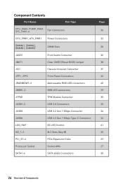
... Port Type CPU_FAN1, PUMP_FAN1, SYS_FAN1~6 Fan Connectors CPU_PWR1, ATX_PWR1 Power Connectors DIMMA1, DIMMA2, DIMMB1, DIMMB2 DIMM Slots JAUD1 Front Audio Connector JBAT1 Clear CMOS (Reset BIOS) Jumper JCI1 Chassis Intrusion Connector JFP1, JFP2 Front Panel Connectors JRAINBOW1~2 Addressable RGB LED connectors JRGB1~2 RGB LED connectors JTPM1 TPM Module Connector JUSB1~2 USB...
... Port Type CPU_FAN1, PUMP_FAN1, SYS_FAN1~6 Fan Connectors CPU_PWR1, ATX_PWR1 Power Connectors DIMMA1, DIMMA2, DIMMB1, DIMMB2 DIMM Slots JAUD1 Front Audio Connector JBAT1 Clear CMOS (Reset BIOS) Jumper JCI1 Chassis Intrusion Connector JFP1, JFP2 Front Panel Connectors JRAINBOW1~2 Addressable RGB LED connectors JRGB1~2 RGB LED connectors JTPM1 TPM Module Connector JUSB1~2 USB...
User Manual
Page 27
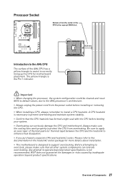
Before attempting to assist in the heatsink/ cooler package for motherboard placement. MSI® does not guarantee the damages or risks caused by inadequate operation beyond product specifications is designed to protect the CPU from the power outlet ... and motherboard. A CPU heatsink is the Pin 1 indicator. ⚠⚠Important ∙∙When changing the processor, the system configuration could be cleared and reset BIOS to default values, due to the AM4 processor's architecture. ∙∙Always unplug the power cord from overheating.
Before attempting to assist in the heatsink/ cooler package for motherboard placement. MSI® does not guarantee the damages or risks caused by inadequate operation beyond product specifications is designed to protect the CPU from the power outlet ... and motherboard. A CPU heatsink is the Pin 1 indicator. ⚠⚠Important ∙∙When changing the processor, the system configuration could be cleared and reset BIOS to default values, due to the AM4 processor's architecture. ∙∙Always unplug the power cord from overheating.
User Manual
Page 28
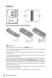
... modules in the DIMMA2 slot first. ∙∙Due to the memory frequency operates dependent on its Serial Presence Detect (SPD). Go to BIOS and find the DRAM Frequency to set the memory frequency if you want to operate the memory at the marked or at a higher frequency....overclocking. ∙∙The stability and compatibility of installed memory module depend on installed CPU and devices when overclocking. ∙∙Please refer www.msi.com for more information on compatible memory. 28 Overview of the same type, number and density. ∙∙Some memory modules may operate at...
... modules in the DIMMA2 slot first. ∙∙Due to the memory frequency operates dependent on its Serial Presence Detect (SPD). Go to BIOS and find the DRAM Frequency to set the memory frequency if you want to operate the memory at the marked or at a higher frequency....overclocking. ∙∙The stability and compatibility of installed memory module depend on installed CPU and devices when overclocking. ∙∙Please refer www.msi.com for more information on compatible memory. 28 Overview of the same type, number and density. ∙∙Some memory modules may operate at...
User Manual
Page 36
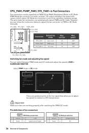
... 1A Max. Select PWM mode or DC mode There are working properly after switching the PWM/ DC mode. However, you to adjust fan speed in BIOS > HARDWARE MONITOR. CPU_FAN1, PUMP_FAN1, SYS_FAN1~6: Fan Connectors Fan connectors can follow the instruction below to adjust the fan connector to PWM or DC Mode manually...
... 1A Max. Select PWM mode or DC mode There are working properly after switching the PWM/ DC mode. However, you to adjust fan speed in BIOS > HARDWARE MONITOR. CPU_FAN1, PUMP_FAN1, SYS_FAN1~6: Fan Connectors Fan connectors can follow the instruction below to adjust the fan connector to PWM or DC Mode manually...
User Manual
Page 37
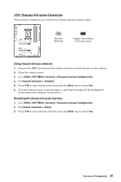
... computer is turned on the chassis. 2. Press F10 to save and exit and then press the Enter key to select Yes. 6. Set Chassis Intrusion to BIOS > SETTINGS > Security > Chassis Intrusion Configuration. 2. Go to the chassis intrusion switch/ sensor on . Overview of Components 37 Resetting the chassis intrusion warning 1. Press F10 to... save and exit and then press the Enter key to select Yes. Connect the JCI1 connector to BIOS > SETTINGS > Security > Chassis Intrusion Configuration. 4. Close the chassis cover. 3.
... computer is turned on the chassis. 2. Press F10 to save and exit and then press the Enter key to select Yes. 6. Set Chassis Intrusion to BIOS > SETTINGS > Security > Chassis Intrusion Configuration. 2. Go to the chassis intrusion switch/ sensor on . Overview of Components 37 Resetting the chassis intrusion warning 1. Press F10 to... save and exit and then press the Enter key to select Yes. Connect the JCI1 connector to BIOS > SETTINGS > Security > Chassis Intrusion Configuration. 4. Close the chassis cover. 3.
User Manual
Page 38
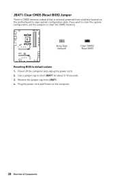
JBAT1: Clear CMOS (Reset BIOS) Jumper There is CMOS memory onboard that is external powered from JBAT1. 4. If you want to clear the system configuration, set the jumpers to save system configuration data. Remove the jumper cap from a battery located on the computer. 38 Overview of Components Keep Data (default) Clear CMOS/ Reset BIOS Resetting BIOS to short JBAT1 for about 5-10 seconds. 3. Plug the power cord and Power on the motherboard to clear the CMOS memory. Use a jumper cap to default values 1. Power off the computer and unplug the power cord. 2.
JBAT1: Clear CMOS (Reset BIOS) Jumper There is CMOS memory onboard that is external powered from JBAT1. 4. If you want to clear the system configuration, set the jumpers to save system configuration data. Remove the jumper cap from a battery located on the computer. 38 Overview of Components Keep Data (default) Clear CMOS/ Reset BIOS Resetting BIOS to short JBAT1 for about 5-10 seconds. 3. Plug the power cord and Power on the motherboard to clear the CMOS memory. Use a jumper cap to default values 1. Power off the computer and unplug the power cord. 2.
User Manual
Page 43
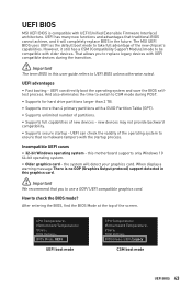
... number of partitions. ∙∙Supports full capabilities of the new chipset's capabilities. UEFI can directly boot the operating system and save the BIOS selftest process. UEFI advantages ∙∙Fast booting - UEFI BIOS MSI UEFI BIOS is no malware tampers with the startup process. UEFI has many new functions and advantages that traditional...
... number of partitions. ∙∙Supports full capabilities of the new chipset's capabilities. UEFI can directly boot the operating system and save the BIOS selftest process. UEFI advantages ∙∙Fast booting - UEFI BIOS MSI UEFI BIOS is no malware tampers with the startup process. UEFI has many new functions and advantages that traditional...
User Manual
Page 44
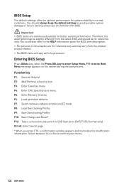
...the default settings to enter Boot Menu message appears on the screen during the boot process. You should be for reference only. Entering BIOS Setup Press Delete key, when the Press DEL key to enter Setup Menu, F11 to avoid possible system damage or failure booting ...unless you purchased. ∙∙The BIOS items will vary with BIOS. ⚠⚠Important ∙∙BIOS items are continuously update for better system performance. Select between Advanced mode and EZ mode F8: Load Overclocking Profile...
...the default settings to enter Boot Menu message appears on the screen during the boot process. You should be for reference only. Entering BIOS Setup Press Delete key, when the Press DEL key to enter Setup Menu, F11 to avoid possible system damage or failure booting ...unless you purchased. ∙∙The BIOS items will vary with BIOS. ⚠⚠Important ∙∙BIOS items are continuously update for better system performance. Select between Advanced mode and EZ mode F8: Load Overclocking Profile...
User Manual
Page 45
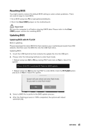
...the USB flash drive that matches your motherboard model from MSI website. Press to activate M-Flash for resetting BIOS. Updating BIOS: 1. Select a BIOS file to reboot the system. 3. Please refer to the Clear CMOS jumper section for BIOS update. ▪▪Reboot and press Del key during ...system will reboot automatically. After the flashing process is off before clearing CMOS data. UEFI BIOS 45 Updating BIOS Updating BIOS with M-FLASH Before updating: Please download the latest BIOS file that contains the update file into the USB flash drive. Please refer the following ...
...the USB flash drive that matches your motherboard model from MSI website. Press to activate M-Flash for resetting BIOS. Updating BIOS: 1. Select a BIOS file to reboot the system. 3. Please refer to the Clear CMOS jumper section for BIOS update. ▪▪Reboot and press Del key during ...system will reboot automatically. After the flashing process is off before clearing CMOS data. UEFI BIOS 45 Updating BIOS Updating BIOS with M-FLASH Before updating: Please download the latest BIOS file that contains the update file into the USB flash drive. Please refer the following ...
User Manual
Page 46
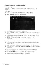
.... 5. Click Next and choose In Windows mode. Please download the latest BIOS file that contains the MSI.ROM file into the Flash BIOS Port on Scan button to download and install the latest BIOS file. 5. Updating BIOS: 1. Select Live Update and click on Download icon to search the latest...click Next and Start to install CPU and memory.) 4. Updating BIOS with MSI DRAGON CENTER Before updating: Make sure the LAN driver is already installed and the internet connection is set properly. Updating the BIOS with Flash BIOS Button 1. Connect the power supply to CPU_PWR1 and ATX_PWR1. (...
.... 5. Click Next and choose In Windows mode. Please download the latest BIOS file that contains the MSI.ROM file into the Flash BIOS Port on Scan button to download and install the latest BIOS file. 5. Updating BIOS: 1. Select Live Update and click on Download icon to search the latest...click Next and Start to install CPU and memory.) 4. Updating BIOS with MSI DRAGON CENTER Before updating: Make sure the LAN driver is already installed and the internet connection is set properly. Updating the BIOS with Flash BIOS Button 1. Connect the power supply to CPU_PWR1 and ATX_PWR1. (...
User Manual
Page 47
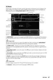
... Advanced mode and EZ mode. ∙∙ Screenshot - EZ Mode At EZ mode, it provides the basic system information and allows you to adjust any BIOS item after activating the GAME BOOST function for keeping the optimal performance and system stability. ∙∙ A-XMP Profile - press this function. ⚠⚠.... This function is only available when the system, memory and CPU are supporting this function. ∙∙ Setup Mode switch - To configure the advanced BIOS settings, please enter the Advanced Mode by BIOS item name. This function is only available when both of...
... Advanced mode and EZ mode. ∙∙ Screenshot - EZ Mode At EZ mode, it provides the basic system information and allows you to adjust any BIOS item after activating the GAME BOOST function for keeping the optimal performance and system stability. ∙∙ A-XMP Profile - press this function. ⚠⚠.... This function is only available when the system, memory and CPU are supporting this function. ∙∙ Setup Mode switch - To configure the advanced BIOS settings, please enter the Advanced Mode by BIOS item name. This function is only available when both of...
User Manual
Page 48
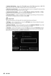
... to manually control the fan speed by clicking on this button or press the F3 key to create personal BIOS menu where you can save and access favorite/ frequently-used BIOS setting items. 48 UEFI BIOS shows the CPU/ DDR speed, CPU/ MB temperature, MB/ CPU type, memory size, CPU/ DDR ..., Fan Info and Help buttons to change the boot priority. click on this button to enter the M-Flash menu that provides the way to update BIOS with the motherboard you to enter the Hardware Monitor menu that allows you purchased. ∙∙ M-Flash - click on these buttons. It provides 5 menus...
... to manually control the fan speed by clicking on this button or press the F3 key to create personal BIOS menu where you can save and access favorite/ frequently-used BIOS setting items. 48 UEFI BIOS shows the CPU/ DDR speed, CPU/ MB temperature, MB/ CPU type, memory size, CPU/ DDR ..., Fan Info and Help buttons to change the boot priority. click on this button to enter the M-Flash menu that provides the way to update BIOS with the motherboard you to enter the Hardware Monitor menu that allows you purchased. ∙∙ M-Flash - click on these buttons. It provides 5 menus...
User Manual
Page 49
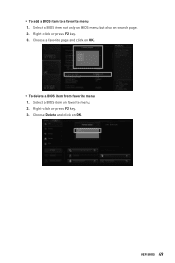
Choose a favorite page and click on OK. Choose Delete and click on OK. ▪▪To delete a BIOS item from favorite menu 1. UEFI BIOS 49 Right-click or press F2 key. 3. Select a BIOS item not only on BIOS menu but also on favorite menu. 2. ▪▪To add a BIOS item to a favorite menu 1. Right-click or press F2 key. 3. Select a BIOS item on search page. 2.
Choose a favorite page and click on OK. Choose Delete and click on OK. ▪▪To delete a BIOS item from favorite menu 1. UEFI BIOS 49 Right-click or press F2 key. 3. Select a BIOS item not only on BIOS menu but also on favorite menu. 2. ▪▪To add a BIOS item to a favorite menu 1. Right-click or press F2 key. 3. Select a BIOS item on search page. 2.


