User Guide
Page 12
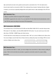
...vendors for jumper setting instructions. 8 CPUFAN1 supports the fan control. IDE2 can connect a Master and a Slave drive. MSI Reminds You... You can connect up to four hard disk drives, CD-ROM, 120MB Floppy and other devices. Refer to the actual CPU temperature. take advantage of the CPU fan control. MSI Reminds You...... fan. 2. If the mainboard has a System Hardware Monitor chipset on cable, you must configure second hard drive to Slave mode by setting the jumper accordingly. If you install two hard disks on -board, you must configure the second drive to Slave mode by...
...vendors for jumper setting instructions. 8 CPUFAN1 supports the fan control. IDE2 can connect a Master and a Slave drive. MSI Reminds You... You can connect up to four hard disk drives, CD-ROM, 120MB Floppy and other devices. Refer to the actual CPU temperature. take advantage of the CPU fan control. MSI Reminds You...... fan. 2. If the mainboard has a System Hardware Monitor chipset on cable, you must configure second hard drive to Slave mode by setting the jumper accordingly. If you install two hard disks on -board, you must configure the second drive to Slave mode by...
User Guide
Page 14
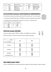
... RXN 7 GND PIN SIGNAL 2 TXP 4 GND 6 RXP FSB Clock Jumper: SW1/SW2 These two jumpers provide 100MHz, 133MHz, and 166MHz Front Side Bus frequency selection. Follow the instructions below to adjust the jumpers. 3 3 1 1 SW1 SW2 Jumper CPU Frequency 133 MHz 166 MHz 200 MHz (for KM400/KM400A ) The... Out or 9 Transmit Data SIGNAL DSR RTS CTS RI DESCRIPTION Data Set Ready Request To Send Clear To Send Ring Indicate Serial ATA HDD Connectors: SATA1/SATA2 (for KM400A only) SW1 3 1 3 1 3 1 SW2 3 1 3 1 3 1 Clear CMOS Jumper: JBAT1 There is a CMOS RAM on board that has a power...
... RXN 7 GND PIN SIGNAL 2 TXP 4 GND 6 RXP FSB Clock Jumper: SW1/SW2 These two jumpers provide 100MHz, 133MHz, and 166MHz Front Side Bus frequency selection. Follow the instructions below to adjust the jumpers. 3 3 1 1 SW1 SW2 Jumper CPU Frequency 133 MHz 166 MHz 200 MHz (for KM400/KM400A ) The... Out or 9 Transmit Data SIGNAL DSR RTS CTS RI DESCRIPTION Data Set Ready Request To Send Clear To Send Ring Indicate Serial ATA HDD Connectors: SATA1/SATA2 (for KM400A only) SW1 3 1 3 1 3 1 SW2 3 1 3 1 3 1 Clear CMOS Jumper: JBAT1 There is a CMOS RAM on board that has a power...
User Guide
Page 15
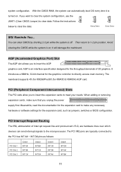
...abbreviation of 3D graphics. Follow the instructions 1 1 1 below to 1-2 pin position. Then return to clear the data: Keep Data Clear Data MSI Reminds You... It introduces a 66MHz, 32-bit channel for the graphics controller to make sure that you to the PCI bus INT A# ~ INT... D# pins as jumpers, switches or BIOS configuration. When adding or removing expansion cards, make any necessary hardware or software settings for the throughput demands of interrupt request line and pronounced I-R-Q, are typically connected to...
...abbreviation of 3D graphics. Follow the instructions 1 1 1 below to 1-2 pin position. Then return to clear the data: Keep Data Clear Data MSI Reminds You... It introduces a 66MHz, 32-bit channel for the graphics controller to make sure that you to the PCI bus INT A# ~ INT... D# pins as jumpers, switches or BIOS configuration. When adding or removing expansion cards, make any necessary hardware or software settings for the throughput demands of interrupt request line and pronounced I-R-Q, are typically connected to...

