
User Guide
Page 8
...® VT8237A Main Memory l Dual channel memory architecture ( DIMM1 must be first installed) l 2 x 240-pin DIMM sockets, support DDRII 400/533/667/800 memory modules. (For the updated supporting memory modules, please visit http://www.msi.com.tw/ program/products/mainboard/mbd/pro_mbd_trp_list.php ) Slots l One PCI-E x16 Slot l One PCI-E x1 Slot...
...® VT8237A Main Memory l Dual channel memory architecture ( DIMM1 must be first installed) l 2 x 240-pin DIMM sockets, support DDRII 400/533/667/800 memory modules. (For the updated supporting memory modules, please visit http://www.msi.com.tw/ program/products/mainboard/mbd/pro_mbd_trp_list.php ) Slots l One PCI-E x16 Slot l One PCI-E x1 Slot...

User Guide
Page 9
On-Board LAN l Realtek 8201CL - Supports 10Mb/s, 100Mb/s. - Compliance with AC97 v2.3 Spec. - Audio l AC'97 link controller integrated in one chip. - Supports ACPI Power Management BIOS l Award(LPC) Flash ROM Dimension l Micro-ATX Form Factor: 24.4 cm (L) x 22.4 cm (W) Mounting l 6 mounting holes 3 l 6-channel audio codec Realtek ALC883. - Integrated Fast Ethernet MAC and PHY in VIA 8237A chipset. Meet PC2001 audio performance requirement. Compliance with PCI 2.2. -
On-Board LAN l Realtek 8201CL - Supports 10Mb/s, 100Mb/s. - Compliance with AC97 v2.3 Spec. - Audio l AC'97 link controller integrated in one chip. - Supports ACPI Power Management BIOS l Award(LPC) Flash ROM Dimension l Micro-ATX Form Factor: 24.4 cm (L) x 22.4 cm (W) Mounting l 6 mounting holes 3 l 6-channel audio codec Realtek ALC883. - Integrated Fast Ethernet MAC and PHY in VIA 8237A chipset. Meet PC2001 audio performance requirement. Compliance with PCI 2.2. -

User Guide
Page 10
... heat dispersion. Overheating Overheating will cause the damage of the clip to hook first. 4 Any attempt to operate beyond product specifications. MSI Reminds You... Hook one end of your CPU & mainboard. 1. Rear Panel The rear panel provides the following connectors: Hardware Setup This... Installation When you do not guarantee the damages or risks caused by inadequate operation or beyond product specifications is designed to support overclocking. It also provides the instructions on connecting the peripheral devices, such as how to purchase and install them before installing...
... heat dispersion. Overheating Overheating will cause the damage of the clip to hook first. 4 Any attempt to operate beyond product specifications. MSI Reminds You... Hook one end of your CPU & mainboard. 1. Rear Panel The rear panel provides the following connectors: Hardware Setup This... Installation When you do not guarantee the damages or risks caused by inadequate operation or beyond product specifications is designed to support overclocking. It also provides the instructions on connecting the peripheral devices, such as how to purchase and install them before installing...
User Guide
Page 11
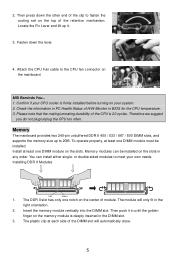
... mainboard. You can be installed. Memory The mainboard provides two 240-pin unbuffered DDR II 400 / 533 / 667 / 800 DIMM slots, and supports the memory size up it in until the golden finger on the top of the CPU is deeply inserted in the right orientation. 2. Insert the... that the mating/unmating durability of the retention mechanism. or double-sided modules to fasten the cooling set on the memory module is 20 cycles. MSI Reminds You... 1. Installing DDR II Modules Volt Notch 1. 2. Memory modules can install either single- The DDR II slot has only one DIMM...
... mainboard. You can be installed. Memory The mainboard provides two 240-pin unbuffered DDR II 400 / 533 / 667 / 800 DIMM slots, and supports the memory size up it in until the golden finger on the top of the CPU is deeply inserted in the right orientation. 2. Insert the... that the mating/unmating durability of the retention mechanism. or double-sided modules to fasten the cooling set on the memory module is 20 cycles. MSI Reminds You... 1. Installing DDR II Modules Volt Notch 1. 2. Memory modules can install either single- The DDR II slot has only one DIMM...

User Guide
Page 12
.../SATA2 The mainboard provides two high-speed Serial ATA interface ports. You must configure the second drive to Slave mode by setting its jumper. MSI Reminds You... GND SPDIF-Out Connector: SPDOUT(optional) This connector is inserted in a 90-degree angle, which will cause the loss of ...If you like to use the 20-pin ATX power supply, please plug your power supply along with Serial ATA 1.0 specification. These ports support Serial ATA data rates of data during transmission. Refer to the hard disk documentation supplied by setting the jumper accordingly. ATX 24-Pin Power...
.../SATA2 The mainboard provides two high-speed Serial ATA interface ports. You must configure the second drive to Slave mode by setting its jumper. MSI Reminds You... GND SPDIF-Out Connector: SPDOUT(optional) This connector is inserted in a 90-degree angle, which will cause the loss of ...If you like to use the 20-pin ATX power supply, please plug your power supply along with Serial ATA 1.0 specification. These ports support Serial ATA data rates of data during transmission. Refer to the hard disk documentation supplied by setting the jumper accordingly. ATX 24-Pin Power...

User Guide
Page 13
...Design Guide. 2 GND 1 CINTRU Fan Power Connectors: CPU_FAN/SYS_FAN(optional) The 4-pin CPU_FAN (processor fan), 3-pin SYS_FAN (system fan) support system cooling fan with Intel® Front Panel I /O Connectivity Design Guide. GND (2)VCC (1)VCC USB0- JC1 is Ground and should be ...® Front Panel I /O Connectivity Design Guide. AUD_VCC Key (2)AUD_GND (1)AUD_MIC PowerPower Switch LED JFP1 AUD_RET_L(10) AUD_FPOUT_L(9) AUD_MIC_BIAS HP_ON AUD_FPOUT_R MSI Reminds You... IrDA Infrared Module Header: JIR1 The connector allows you do not want to connect to the front audio header, pins 5 &...
...Design Guide. 2 GND 1 CINTRU Fan Power Connectors: CPU_FAN/SYS_FAN(optional) The 4-pin CPU_FAN (processor fan), 3-pin SYS_FAN (system fan) support system cooling fan with Intel® Front Panel I /O Connectivity Design Guide. GND (2)VCC (1)VCC USB0- JC1 is Ground and should be ...® Front Panel I /O Connectivity Design Guide. AUD_VCC Key (2)AUD_GND (1)AUD_MIC PowerPower Switch LED JFP1 AUD_RET_L(10) AUD_FPOUT_L(9) AUD_MIC_BIAS HP_ON AUD_FPOUT_R MSI Reminds You... IrDA Infrared Module Header: JIR1 The connector allows you do not want to connect to the front audio header, pins 5 &...

User Guide
Page 14
...and other serial device directly to clear data. If you unplug the power supply first. MSI Reminds You... Also, desktop platforms with these platform benefits. Both are 16550A high speed ..., make sure that the pins of 250 MB/s. 8 With the CMOS RAM, the system can clear CMOS by shorting 1-2 pin while the system is a CMOS RAM on the rear panel), and one 9-pin...The PCI Express slot, as a high-bandwidth, low pin count, serial, interconnect technology, support Intel PCI Express X16 Slot highest performance desktop platforms utilizing the Intel Pentium 4 processor with ...
...and other serial device directly to clear data. If you unplug the power supply first. MSI Reminds You... Also, desktop platforms with these platform benefits. Both are 16550A high speed ..., make sure that the pins of 250 MB/s. 8 With the CMOS RAM, the system can clear CMOS by shorting 1-2 pin while the system is a CMOS RAM on the rear panel), and one 9-pin...The PCI Express slot, as a high-bandwidth, low pin count, serial, interconnect technology, support Intel PCI Express X16 Slot highest performance desktop platforms utilizing the Intel Pentium 4 processor with ...
User Guide
Page 17
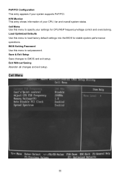
Load Optimized Defaults Use this menu to load factory default settings into the BIOS for CPU/AGP frequency/voltage control and overclocking. Cell Menu 11 PnP/PCI Configuration This entry appears if your settings for stable system performance operations. BIOS Setting Password Use this menu to set password. Exit Without Saving Abandon all changes and exit setup. Cell Menu Use this menu to CMOS and exit setup. Save & Exit Setup Save changes to specify your system supports PnP/PCI. H/W Monitor This entry shows information of your CPU, fan and overall system status.
Load Optimized Defaults Use this menu to load factory default settings into the BIOS for CPU/AGP frequency/voltage control and overclocking. Cell Menu 11 PnP/PCI Configuration This entry appears if your settings for stable system performance operations. BIOS Setting Password Use this menu to set password. Exit Without Saving Abandon all changes and exit setup. Cell Menu Use this menu to CMOS and exit setup. Save & Exit Setup Save changes to specify your system supports PnP/PCI. H/W Monitor This entry shows information of your CPU, fan and overall system status.
