
User Guide
Page 8
Specifications CPU l Supports Socket-940 for AMD Athlon 64 / Athlon 64 X2 / Sempron / M2 processor (For the latest information about CPU, please visit http://www.msi.com.tw/program/ products/mainboard/mbd/pro_mbd_cpu_support.php ) Chipset l Northbridge: VIA® K8M890 l Southbridge: VIA® VT8237A Main Memory l Dual channel memory architecture ( DIMM1 must ...
Specifications CPU l Supports Socket-940 for AMD Athlon 64 / Athlon 64 X2 / Sempron / M2 processor (For the latest information about CPU, please visit http://www.msi.com.tw/program/ products/mainboard/mbd/pro_mbd_cpu_support.php ) Chipset l Northbridge: VIA® K8M890 l Southbridge: VIA® VT8237A Main Memory l Dual channel memory architecture ( DIMM1 must ...

User Guide
Page 10
... 4 Meanwhile, do not guarantee the damages or risks caused by inadequate operation or beyond product specifications is designed to support overclocking. Hook one end of your CPU & mainboard. 1. Rear Panel The rear panel provides the following connectors: Hardware Setup This chapter tells you how to... install the CPU, memory modules, and expansion cards, as well as the mouse, keyboard, etc. Follow the steps below to prevent overheating. MSI Reminds You... Overheating Overheating will cause the damage of the clip ...
... 4 Meanwhile, do not guarantee the damages or risks caused by inadequate operation or beyond product specifications is designed to support overclocking. Hook one end of your CPU & mainboard. 1. Rear Panel The rear panel provides the following connectors: Hardware Setup This chapter tells you how to... install the CPU, memory modules, and expansion cards, as well as the mouse, keyboard, etc. Follow the steps below to prevent overheating. MSI Reminds You... Overheating Overheating will cause the damage of the clip ...
User Guide
Page 11
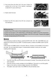
... of the clip to meet your system. 2. Memory The mainboard provides two 240-pin unbuffered DDR II 400 / 533 / 667 / 800 DIMM slots, and supports the memory size up it in until the golden finger on your own needs. Insert the memory module vertically into the DIMM slot. Confirm if...installed on the top of module. Locate the Fix Lever and lift up to the CPU fan connector on the center of the retention mechanism. MSI Reminds You... 1. Therefore we suggest you do not plug/unplug the CPU too often. Please note that the mating/unmating durability of the DIMM slot will only...
... of the clip to meet your system. 2. Memory The mainboard provides two 240-pin unbuffered DDR II 400 / 533 / 667 / 800 DIMM slots, and supports the memory size up it in until the golden finger on your own needs. Insert the memory module vertically into the DIMM slot. Confirm if...installed on the top of module. Locate the Fix Lever and lift up to the CPU fan connector on the center of the retention mechanism. MSI Reminds You... 1. Therefore we suggest you do not plug/unplug the CPU too often. Please note that the mating/unmating durability of the DIMM slot will only...

User Guide
Page 12
... Power Connector: JPW1 21 GND GND This 12V power connector is used to provide power to the CPU. 12V 12V 43 Floppy Disk Drive Connector: FDD1 The mainboard provides a standard floppy disk drive connector that supports 360K, 720K, 1.2M, 1.44M and 2.88M floppy disk types. +3.3V +3.3V GND +5V GND +5V GND... always be connected to the hard disk documentation supplied by hard disk vendors for CD-ROM audio connector. IDE1 can connect a Master and a Slave drive. MSI Reminds You... SPDIF VCC 6
... Power Connector: JPW1 21 GND GND This 12V power connector is used to provide power to the CPU. 12V 12V 43 Floppy Disk Drive Connector: FDD1 The mainboard provides a standard floppy disk drive connector that supports 360K, 720K, 1.2M, 1.44M and 2.88M floppy disk types. +3.3V +3.3V GND +5V GND +5V GND... always be connected to the hard disk documentation supplied by hard disk vendors for CD-ROM audio connector. IDE1 can connect a Master and a Slave drive. MSI Reminds You... SPDIF VCC 6

User Guide
Page 13
...Key(9) 7 AUD_VCC Key (2)AUD_GND (1)AUD_MIC PowerPower Switch LED JFP1 AUD_RET_L(10) AUD_FPOUT_L(9) AUD_MIC_BIAS HP_ON AUD_FPOUT_R MSI Reminds You... If you do not want to connect to the front audio header, pins 5 &...Connectors: CPU_FAN/SYS_FAN(optional) The 4-pin CPU_FAN (processor fan), 3-pin SYS_FAN (system fan) support system cooling fan with Intel® Front Panel I /O Connectivity Design Guide. If the mainboard... JIR1 The connector allows you to connect to a maximum throughput of the CPU fan control. When connecting the wire to the connectors, always take advantage ...
...Key(9) 7 AUD_VCC Key (2)AUD_GND (1)AUD_MIC PowerPower Switch LED JFP1 AUD_RET_L(10) AUD_FPOUT_L(9) AUD_MIC_BIAS HP_ON AUD_FPOUT_R MSI Reminds You... If you do not want to connect to the front audio header, pins 5 &...Connectors: CPU_FAN/SYS_FAN(optional) The 4-pin CPU_FAN (processor fan), 3-pin SYS_FAN (system fan) support system cooling fan with Intel® Front Panel I /O Connectivity Design Guide. If the mainboard... JIR1 The connector allows you to connect to a maximum throughput of the CPU fan control. When connecting the wire to the connectors, always take advantage ...
User Guide
Page 17
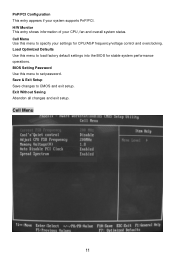
Load Optimized Defaults Use this menu to specify your settings for stable system performance operations. Save & Exit Setup Save changes to set password. H/W Monitor This entry shows information of your system supports PnP/PCI. BIOS Setting Password Use this menu to load factory default settings into the BIOS for CPU/AGP frequency/voltage control and overclocking. PnP/PCI Configuration This entry appears if your CPU, fan and overall system status. Cell Menu 11 Exit Without Saving Abandon all changes and exit setup. Cell Menu Use this menu to CMOS and exit setup.
Load Optimized Defaults Use this menu to specify your settings for stable system performance operations. Save & Exit Setup Save changes to set password. H/W Monitor This entry shows information of your system supports PnP/PCI. BIOS Setting Password Use this menu to load factory default settings into the BIOS for CPU/AGP frequency/voltage control and overclocking. PnP/PCI Configuration This entry appears if your CPU, fan and overall system status. Cell Menu 11 Exit Without Saving Abandon all changes and exit setup. Cell Menu Use this menu to CMOS and exit setup.
