
User Guide
Page 2
... http://global.msi.com.tw/index.php? We take every care in the preparation of this document is a registered trademark of Phoenix Technologies Ltd. Alternatively, please try the following help resources for FAQ, technical guide, BIOS updates, driver updates, and other countries. Revision History Revision V2.0 Revision History First release Date October 2007 Technical Support If a problem arises with...
... http://global.msi.com.tw/index.php? We take every care in the preparation of this document is a registered trademark of Phoenix Technologies Ltd. Alternatively, please try the following help resources for FAQ, technical guide, BIOS updates, driver updates, and other countries. Revision History Revision V2.0 Revision History First release Date October 2007 Technical Support If a problem arises with...
User Guide
Page 8
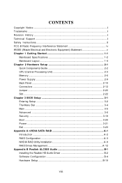
...Specifications 1-2 Mainboard Layout 1-4 Chapter 2 Hardware Setup 2-1 Quick Components Guide 2-2 CPU (Central Processing Unit 2-3 Memory ...2-6 Power Supply ...2-9 Back Panel ...2-10 Connectors ...2-12 Jumper ...2-20 Slot ...2-22 Chapter 3 BIOS Setup 3-1 Entering Setup ...3-2 The Menu Bar ...3-4 Main ...3-5 Advanc ed ...3-6 Security ...3-19 Boot ...3-20 Power ...3-21 Exit ...3-23 Appendix A nVIDIA SATA RAID A-1 Introduction ...A-2 RAID Configuration A-3 NVIDIA RAID Utility Installation A-9 RAID Drives Management A-12 Appendix B Realtek ALC888 Audio B-1 Installing the Realtek HD Audio...
...Specifications 1-2 Mainboard Layout 1-4 Chapter 2 Hardware Setup 2-1 Quick Components Guide 2-2 CPU (Central Processing Unit 2-3 Memory ...2-6 Power Supply ...2-9 Back Panel ...2-10 Connectors ...2-12 Jumper ...2-20 Slot ...2-22 Chapter 3 BIOS Setup 3-1 Entering Setup ...3-2 The Menu Bar ...3-4 Main ...3-5 Advanc ed ...3-6 Security ...3-19 Boot ...3-20 Power ...3-21 Exit ...3-23 Appendix A nVIDIA SATA RAID A-1 Introduction ...A-2 RAID Configuration A-3 NVIDIA RAID Utility Installation A-9 RAID Drives Management A-12 Appendix B Realtek ALC888 Audio B-1 Installing the Realtek HD Audio...
User Guide
Page 9
...-pin package and supports up to 8 Registered ECC DDR2 400/533/667 DIMM slots to provide the maximum of 32GB memory capacity. In the entry-level and mid-range market segment, the K9NU Speedster can provide a high-performance solution for optimal system efficiency, the K9NU Speedster accommodates the latest AMD® Opteron processor in the future. 1-1 Getting Started Chapter 1 Getting Started...
...-pin package and supports up to 8 Registered ECC DDR2 400/533/667 DIMM slots to provide the maximum of 32GB memory capacity. In the entry-level and mid-range market segment, the K9NU Speedster can provide a high-performance solution for optimal system efficiency, the K9NU Speedster accommodates the latest AMD® Opteron processor in the future. 1-1 Getting Started Chapter 1 Getting Started...

User Guide
Page 10
.../s Floppy - 1 floppy port IEEE 1394 - XGI Z7 graphics controller - Onboard 16MB Video SDRAM 1-2 Meets thermal requirements Chipset - HyperTransport interface capable of operating up to 2000 MT/s - IDE - 1-channel bus master IDE port - VIA VT6308 IEEE 1394 controller LAN - 2 Gigabit Ethernet controllers bundled into Marvell 88E1116 (MCP55V Pro) Audio - But when 5~8 DIMMs are installed, memory will automatically tune the memory frequency down to 533MHz due to AMD CPU limitations. Storage and data transfers at 667MHz. Supports single AMD...
.../s Floppy - 1 floppy port IEEE 1394 - XGI Z7 graphics controller - Onboard 16MB Video SDRAM 1-2 Meets thermal requirements Chipset - HyperTransport interface capable of operating up to 2000 MT/s - IDE - 1-channel bus master IDE port - VIA VT6308 IEEE 1394 controller LAN - 2 Gigabit Ethernet controllers bundled into Marvell 88E1116 (MCP55V Pro) Audio - But when 5~8 DIMMs are installed, memory will automatically tune the memory frequency down to 533MHz due to AMD CPU limitations. Storage and data transfers at 667MHz. Supports single AMD...

User Guide
Page 15
.... 2. Hardware Setup CPU (Central Processing Unit) This mainboard supports the latest AMD® Opteron processor in 1207-Pin Package The pin-pad side The surface Yellow triangle is the Pin 1 indicator Yellow triangle is the Pin 1 indicator Alignment Key Alignment Key Remember to enhance heat dissipation. 3. W hen you are installing the CPU, make sure the cooling fan can work properly to purchase and install it before turning on...
.... 2. Hardware Setup CPU (Central Processing Unit) This mainboard supports the latest AMD® Opteron processor in 1207-Pin Package The pin-pad side The surface Yellow triangle is the Pin 1 indicator Yellow triangle is the Pin 1 indicator Alignment Key Alignment Key Remember to enhance heat dissipation. 3. W hen you are installing the CPU, make sure the cooling fan can work properly to purchase and install it before turning on...
User Guide
Page 24
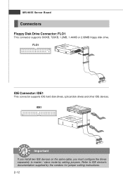
MS-9655 Server Board Connectors Floppy Disk Drive Connector: FLO1 This connector supports 360KB, 720KB, 1.2MB, 1.44MB or 2.88MB floppy disk drive. FLO1 IDE Connector: IDE1 This connector supports IDE hard disk drives, optical disk drives and other IDE devices. Refer to master / slave mode by the vendors for jumper setting instructions. 2-12 IDE1 Important If you install two IDE devices on the same cable, you must configure the drives separately to IDE device's documentation supplied by setting jumpers.
MS-9655 Server Board Connectors Floppy Disk Drive Connector: FLO1 This connector supports 360KB, 720KB, 1.2MB, 1.44MB or 2.88MB floppy disk drive. FLO1 IDE Connector: IDE1 This connector supports IDE hard disk drives, optical disk drives and other IDE devices. Refer to master / slave mode by the vendors for jumper setting instructions. 2-12 IDE1 Important If you install two IDE devices on the same cable, you must configure the drives separately to IDE device's documentation supplied by setting jumpers.
User Guide
Page 26
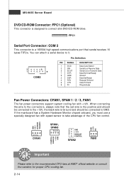
... Please refer to connect slim DVD/CD-ROM drive. If the mainboard has a System Hardware Monitor chipset onboard, you must use a specially designed fan with +12V. MS-9655 Server Board DVD/CD-ROM Connector: FPC1 (Optional) This connector is Ground and should be connected to GND. W hen connecting the wire to the connectors, always note that sends/receives 16 bytes FIFOs. FPC1 Serial Port Connector: COM 2 This connector is a 16550A high speed communications port that the red...
... Please refer to connect slim DVD/CD-ROM drive. If the mainboard has a System Hardware Monitor chipset onboard, you must use a specially designed fan with +12V. MS-9655 Server Board DVD/CD-ROM Connector: FPC1 (Optional) This connector is Ground and should be connected to GND. W hen connecting the wire to the connectors, always note that sends/receives 16 bytes FIFOs. FPC1 Serial Port Connector: COM 2 This connector is a 16550A high speed communications port that the red...

User Guide
Page 32
If you want to clear the system configuration, set this jumper to clear data. 1 JBAT1 3 1 Keep Data 3 1 Clear Data Important You can automatically boot OS every time it will damage the mainboard. 2-20 With the CMOS RAM, the system can clear CMOS by shorting 2-3 pin while the system is turned on ; it is off. Then return to keep the data of system configuration. Avoid clearing the CMOS while the system is a CMOS RAM onboard that has a power supply from external battery to 1-2 pin position. MS-9655 Server Board Jumper Clear CMOS Jumper: JBAT1 There is on .
If you want to clear the system configuration, set this jumper to clear data. 1 JBAT1 3 1 Keep Data 3 1 Clear Data Important You can automatically boot OS every time it will damage the mainboard. 2-20 With the CMOS RAM, the system can clear CMOS by shorting 2-3 pin while the system is turned on ; it is off. Then return to keep the data of system configuration. Avoid clearing the CMOS while the system is a CMOS RAM onboard that has a power supply from external battery to 1-2 pin position. MS-9655 Server Board Jumper Clear CMOS Jumper: JBAT1 There is on .

User Guide
Page 33
... done with the job, the buzzer will beep to remind users to set the jumper to its normal state (pin#1-2 short connected). 1 J9 1 Normal 1 Recovery BIOS Write Protect Jumper: J1 This jumper is used to recover the system BIOS. Hardware Setup VGA Jumper: JVGAD This jumper is used to enable or disable the onboard VGA controller. 1 JVGAD 1 1 3 Enable 3 Disable IEEE1394 Jumper: J1394 This jumper is used to enable or disable the onboard IEEE1394 controller. 1 J1394 1 1 3 Enable 3 Disable BIOS Recovery Jumper: J9 Users can short connect pin#2-3 to enable/disable the BIOS flash.
... done with the job, the buzzer will beep to remind users to set the jumper to its normal state (pin#1-2 short connected). 1 J9 1 Normal 1 Recovery BIOS Write Protect Jumper: J1 This jumper is used to recover the system BIOS. Hardware Setup VGA Jumper: JVGAD This jumper is used to enable or disable the onboard VGA controller. 1 JVGAD 1 1 3 Enable 3 Disable IEEE1394 Jumper: J1394 This jumper is used to enable or disable the onboard IEEE1394 controller. 1 J1394 1 1 3 Enable 3 Disable BIOS Recovery Jumper: J9 Users can short connect pin#2-3 to enable/disable the BIOS flash.

User Guide
Page 34
... Server Board Slot PCI (Peripheral Component Interconnect) Express Slot The PCI Express slot supports the PCI Express interface expansion card. The PCI Express x 16 slot supports up to configure any necessary hardware or software settings for the expansion card, such as jumpers, switches or BIOS configuration. 2-22 PCI Express x1 Slot PCI Express x16 Slot PCI (Peripheral Component Interconnect) Slot The PCI slot supports LAN card, SCSI card, USB card, and other add-on cards that comply with PCI specifications. 32-bit/33MHz PCI Slot Important When adding or removing expansion cards, make...
... Server Board Slot PCI (Peripheral Component Interconnect) Express Slot The PCI Express slot supports the PCI Express interface expansion card. The PCI Express x 16 slot supports up to configure any necessary hardware or software settings for the expansion card, such as jumpers, switches or BIOS configuration. 2-22 PCI Express x1 Slot PCI Express x16 Slot PCI (Peripheral Component Interconnect) Slot The PCI slot supports LAN card, SCSI card, USB card, and other add-on cards that comply with PCI specifications. 32-bit/33MHz PCI Slot Important When adding or removing expansion cards, make...

User Guide
Page 40
Case Open Function The field enables or disables the feature of the CPU host bus (FSB) for end users to overclock the processor. BIOS Write Protect This function protects the BIOS from accidental corruption by unauthorized users or computer viruses. W hen enabled, the BIOS' data cannot be used most commonly. To clear the warning message, set the field to [Enabled] later. The setting of the field will be changed when...
Case Open Function The field enables or disables the feature of the CPU host bus (FSB) for end users to overclock the processor. BIOS Write Protect This function protects the BIOS from accidental corruption by unauthorized users or computer viruses. W hen enabled, the BIOS' data cannot be used most commonly. To clear the warning message, set the field to [Enabled] later. The setting of the field will be changed when...

User Guide
Page 41
Size This setting specifies the memory size for fan power management. System Information This sub-menu shows the system hardware information. 3-7 Fan Type Control This setting allows you should enable this BIOS W rite Protect function. IOM M U AMD64, one of the (64-bit addressed) main memory although with a Flash utility. BIOS Setup ing to update the BIOS with a 32-bit address bus you can only address a 32-bit address space. To successfully update the BIOS, you'll need to...
Size This setting specifies the memory size for fan power management. System Information This sub-menu shows the system hardware information. 3-7 Fan Type Control This setting allows you should enable this BIOS W rite Protect function. IOM M U AMD64, one of the (64-bit addressed) main memory although with a Flash utility. BIOS Setup ing to update the BIOS with a 32-bit address bus you can only address a 32-bit address space. To successfully update the BIOS, you'll need to...

User Guide
Page 42
... is capable of being utilized at once. MS-9655 Server BoardB Memory Controller Options Max Mem Clock Use this field to a single contiguous range of physical addresses. Setting to [Enabled] allows memory to be accessed faster since each processor to configure the highest clock frequency of the installed DRAM. DRAM Bank Interleave Interleaved memory is system memory divided into 4KB blocks, and alternated among the processors. Users may also assign a lower memory clock frequency here.
... is capable of being utilized at once. MS-9655 Server BoardB Memory Controller Options Max Mem Clock Use this field to a single contiguous range of physical addresses. Setting to [Enabled] allows memory to be accessed faster since each processor to configure the highest clock frequency of the installed DRAM. DRAM Bank Interleave Interleaved memory is system memory divided into 4KB blocks, and alternated among the processors. Users may also assign a lower memory clock frequency here.

User Guide
Page 44
... that does not support or have any USB 1.1/2.0 device in an idle state. DRAM ECC Scrub Control The DRAM ECC Scrub option controls the frequency at which memory read options are corrected while the system is in the operating system that protects servers from system downtime caused by memory failures. USB BIOS Legacy Support Set to [Enabled] if your need to be corrected when in DRAM during normal CPU requests (foreground...
... that does not support or have any USB 1.1/2.0 device in an idle state. DRAM ECC Scrub Control The DRAM ECC Scrub option controls the frequency at which memory read options are corrected while the system is in the operating system that protects servers from system downtime caused by memory failures. USB BIOS Legacy Support Set to [Enabled] if your need to be corrected when in DRAM during normal CPU requests (foreground...
User Guide
Page 45
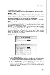
.... BIOS Setup MAC LAN, MAC 1 LAN These settings allow you are using an older operating system like W indows XP. NV RAID Configuration NV RAID Configuration This setting enables/disables the nVIDIA software RAID configuration. The APIC provides multiprocessor support, more IRQs and faster interrupt handling. Interrupt Mode This BIOS feature is set to enable or disable the motherboard's APIC (Advanced Programmable Interrupt Controller). Select PIC only if you to function. Note that the SATA controller must...
.... BIOS Setup MAC LAN, MAC 1 LAN These settings allow you are using an older operating system like W indows XP. NV RAID Configuration NV RAID Configuration This setting enables/disables the nVIDIA software RAID configuration. The APIC provides multiprocessor support, more IRQs and faster interrupt handling. Interrupt Mode This BIOS feature is set to enable or disable the motherboard's APIC (Advanced Programmable Interrupt Controller). Select PIC only if you to function. Note that the SATA controller must...

User Guide
Page 46
... [32-Bit I/O] Enables 32-bit communication between CPU and IDE card 3-12 If your hard disk drive type is not matched or listed, you enter improper information for this setting to [DOS] will operate correctly when [DOS] is selected. Setting to define your drive must match with [Other]. Local Bus IDE Adapter This setting controls the onboard IDE adapter. Compatible illbehaved applications will create a Translated FDPT. MS-9655 Server BoardB IDE Configuration Large Disk Access Mode Defaulting this...
... [32-Bit I/O] Enables 32-bit communication between CPU and IDE card 3-12 If your hard disk drive type is not matched or listed, you enter improper information for this setting to [DOS] will operate correctly when [DOS] is selected. Setting to define your drive must match with [Other]. Local Bus IDE Adapter This setting controls the onboard IDE adapter. Compatible illbehaved applications will create a Translated FDPT. MS-9655 Server BoardB IDE Configuration Large Disk Access Mode Defaulting this...

User Guide
Page 60
... this mainboard with Windows 2000/XP system drivers ONLY. M ul tiple Fault Tol eran ce None Yes Yes No Important Please note that the companion MSI Driver/Utility CD supports this section: RAID 0: RAID 0 defines a disk striping scheme that improves the disk read and write times for 4+ the storage space of 1 drive. Critical data requiring high performance. Optimized for mirroring data. Hence, users cannot install OS...
... this mainboard with Windows 2000/XP system drivers ONLY. M ul tiple Fault Tol eran ce None Yes Yes No Important Please note that the companion MSI Driver/Utility CD supports this section: RAID 0: RAID 0 defines a disk striping scheme that improves the disk read and write times for 4+ the storage space of 1 drive. Critical data requiring high performance. Optimized for mirroring data. Hence, users cannot install OS...

User Guide
Page 61
... RAID BIOS Setup 1. Define a New Array window will reboot right away. Enter the W indows OS, run the W indows nForce Setup application and install the RAID software. 4. Specify the RAID level, either Mirroring (RAID 1) or Striping (RAID 0) and create the desired RAID array. 3. The PC will appear. The default RAID M ode is set to Mirroring and Striping Block is set up the NVRAID BIOS. Boot from the W indows CD, use the floppy disk...
... RAID BIOS Setup 1. Define a New Array window will reboot right away. Enter the W indows OS, run the W indows nForce Setup application and install the RAID software. 4. Specify the RAID level, either Mirroring (RAID 1) or Striping (RAID 0) and create the desired RAID array. 3. The PC will appear. The default RAID M ode is set to Mirroring and Striping Block is set up the NVRAID BIOS. Boot from the W indows CD, use the floppy disk...
User Guide
Page 65
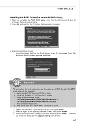
... S again at the Specify Devices screen, then press Enter. (4) Select "NVIDIA NForce Storage Controller" and then press Enter. Insert the MSI CD into the CD-ROM drive. 2. Click the "Browse CD" on the Setup screen. 3. The following W indows Setup screen appears listing both drivers: A-7 The driver disk for the W indows Setup screen to appear. 3. Specify the NVIDIA drivers: (1) Insert the floppy that has the RAID driver, press S, then press Enter. nVIDIA SATA RAID Installing the RAID Driver (for yourself. 1.
... S again at the Specify Devices screen, then press Enter. (4) Select "NVIDIA NForce Storage Controller" and then press Enter. Insert the MSI CD into the CD-ROM drive. 2. Click the "Browse CD" on the Setup screen. 3. The following W indows Setup screen appears listing both drivers: A-7 The driver disk for the W indows Setup screen to appear. 3. Specify the NVIDIA drivers: (1) Insert the floppy that has the RAID driver, press S, then press Enter. nVIDIA SATA RAID Installing the RAID Driver (for yourself. 1.

User Guide
Page 75
... RAID includes extensive support for various morphing combinations. The user must include two disks, converted from a one RAID mode to another . For example, it is possible to morph from a RAID 1 array to a RAID 0 array as long as the RAID 0 array is the same size as (or larger than) the RAID 1 array. • You can't morph from RAID 1 to RAID 1 Specific Morphing Requirements The following table lists...
... RAID includes extensive support for various morphing combinations. The user must include two disks, converted from a one RAID mode to another . For example, it is possible to morph from a RAID 1 array to a RAID 0 array as long as the RAID 0 array is the same size as (or larger than) the RAID 1 array. • You can't morph from RAID 1 to RAID 1 Specific Morphing Requirements The following table lists...


