

User Guide
Page 4
... receiver. † Connect the equipment into an outlet on , the user is subject to comply with Part 15 of the FCC Rules. Micro-Star International MS-7252 This device complies with the emission limits.
... receiver. † Connect the equipment into an outlet on , the user is subject to comply with Part 15 of the FCC Rules. Micro-Star International MS-7252 This device complies with the emission limits.
User Guide
Page 12
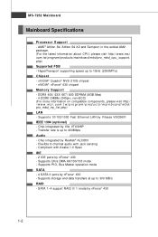
MS-7252 Mainboard Mainboard Specifications Processor Support - Flexible 8-channel audio with Azalia 1.0 Spec IDE - 2 IDE ports by nForce® 430 1-2 c om. t w / pr og ra m/ p r od u c t s / ma in the socket AM2 package. (For the latest information about CPU, please visit http://www.msi. DDRII 400/ 533/ 667/ 800 SDRAM (8GB Max) - 4 DDRII DIMMs (240pin, non...
MS-7252 Mainboard Mainboard Specifications Processor Support - Flexible 8-channel audio with Azalia 1.0 Spec IDE - 2 IDE ports by nForce® 430 1-2 c om. t w / pr og ra m/ p r od u c t s / ma in the socket AM2 package. (For the latest information about CPU, please visit http://www.msi. DDRII 400/ 533/ 667/ 800 SDRAM (8GB Max) - 4 DDRII DIMMs (240pin, non...
User Guide
Page 14
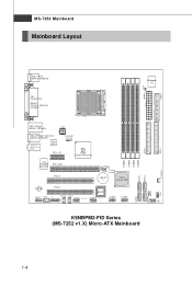
... BIOS JSPDO1 JSPDI1 J1 J13 94_1 (optional) JCOM1 JUSB1 JUSB2 DIMM1 DIMM2 DIMM3 DIMM4 SATA3 SATA4 IDE 2 JFP1 K9NBPM2-FID Series (MS-7252 v1.X) Micro-ATX Mainboard IDE 1 S Y S FA N 1 SATA1 SATA2 JBAT1 J FP2 1-4 JPWR1 JCI1 FDD 1 MS-7252 Mainboard Mainboard Layout Top : mouse Bottom: keyboard Top : Parallel Port Bot to m: DVI port (optional) VGA port...
... BIOS JSPDO1 JSPDI1 J1 J13 94_1 (optional) JCOM1 JUSB1 JUSB2 DIMM1 DIMM2 DIMM3 DIMM4 SATA3 SATA4 IDE 2 JFP1 K9NBPM2-FID Series (MS-7252 v1.X) Micro-ATX Mainboard IDE 1 S Y S FA N 1 SATA1 SATA2 JBAT1 J FP2 1-4 JPWR1 JCI1 FDD 1 MS-7252 Mainboard Mainboard Layout Top : mouse Bottom: keyboard Top : Parallel Port Bot to m: DVI port (optional) VGA port...

User Guide
Page 16
... PC Alert™ 4 icon on the screen, with the abnormal item highlighted in the CD-ROM disk. Click Temperature to send out a warning message. MS-7252 Mainboard MSI Special Feature PC Alert™ 4 The PC AlertTM 4 is abnormal, the program main screen will be shown until the condition returns to be immediately shown...
... PC Alert™ 4 icon on the screen, with the abnormal item highlighted in the CD-ROM disk. Click Temperature to send out a warning message. MS-7252 Mainboard MSI Special Feature PC Alert™ 4 The PC AlertTM 4 is abnormal, the program main screen will be shown until the condition returns to be immediately shown...

User Guide
Page 20
... seen. Please note that any violation of the correct installation procedures may cause permanent damages to your fingers pressing tightly on top of the CPU. MS-7252 Mainboard CPU Installation Procedures for the gold arrow of the CPU to make sure the CPU is properly and completely embedded into the socket. 2-4 Look...
... seen. Please note that any violation of the correct installation procedures may cause permanent damages to your fingers pressing tightly on top of the CPU. MS-7252 Mainboard CPU Installation Procedures for the gold arrow of the CPU to make sure the CPU is properly and completely embedded into the socket. 2-4 Look...

User Guide
Page 22
ph p DDRII 240-pin, 1.8V 56x2=112 pin 64x2=128 pin Dual-Channel Memory Population Rules 1 DIMM1 DIMM2 DIMM3 DIMM4 2 DIMM1 DIMM2 DIMM3 DIMM4 3 DIMM1 DIMM2 DIMM3 DIMM4 2-6 For more information on compatible components, please visit http://www.msi.com.tw/ p ro gr a m/ pr o du c t s /m ain bo ar d /m bd / pr o_ m bd _t r p_ lis t. MS-7252 Mainboard Memory The mainboard provides four 240-pin non-ECC DDRII DIMMs and supports up to 8 GB system memory.
ph p DDRII 240-pin, 1.8V 56x2=112 pin 64x2=128 pin Dual-Channel Memory Population Rules 1 DIMM1 DIMM2 DIMM3 DIMM4 2 DIMM1 DIMM2 DIMM3 DIMM4 3 DIMM1 DIMM2 DIMM3 DIMM4 2-6 For more information on compatible components, please visit http://www.msi.com.tw/ p ro gr a m/ pr o du c t s /m ain bo ar d /m bd / pr o_ m bd _t r p_ lis t. MS-7252 Mainboard Memory The mainboard provides four 240-pin non-ECC DDRII DIMMs and supports up to 8 GB system memory.
User Guide
Page 24
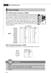
... 350 watts (and above) is inserted in the proper orientation and the pins are aligned. Then push down the power supply firmly into the connector. MS-7252 Mainboard Power Supply ATX 24-Pin Power Connector: JPWR1 This connector allows you 'd like to use the 20-pin ATX power supply as you like...
... 350 watts (and above) is inserted in the proper orientation and the pins are aligned. Then push down the power supply firmly into the connector. MS-7252 Mainboard Power Supply ATX 24-Pin Power Connector: JPWR1 This connector allows you 'd like to use the 20-pin ATX power supply as you like...
User Guide
Page 26
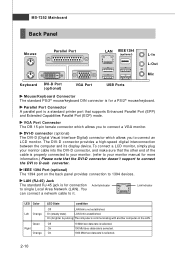
...) The 1394 port on the LAN. Activity Indicator Link Indicator LED Color Left Orange Green Right Orange LED State condition Off LAN link is established. MS-7252 Mainboard Back Panel Mouse Parallel Port LAN IEEE 1394 (optional) L-In L-Out Mic Keyboard DVI-D Port (optional) VGA Port USB Ports Mouse/Keyboard Connector The...
...) The 1394 port on the LAN. Activity Indicator Link Indicator LED Color Left Orange Green Right Orange LED State condition Off LAN link is established. MS-7252 Mainboard Back Panel Mouse Parallel Port LAN IEEE 1394 (optional) L-In L-Out Mic Keyboard DVI-D Port (optional) VGA Port USB Ports Mouse/Keyboard Connector The...
User Guide
Page 28
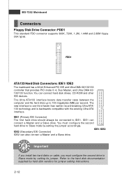
... can also connect a Master and a Slave drive. The Ultra ATA133 interface boosts data transfer rates between the computer and the hard drive up to IDE1. MS-7252 Mainboard Connectors Floppy Disk Drive Connector: FDD1 This standard FDD connector supports 360K, 720K, 1.2M, 1.44M and 2.88M floppy disk types. You must configure the...
... can also connect a Master and a Slave drive. The Ultra ATA133 interface boosts data transfer rates between the computer and the hard drive up to IDE1. MS-7252 Mainboard Connectors Floppy Disk Drive Connector: FDD1 This standard FDD connector supports 360K, 720K, 1.2M, 1.44M and 2.88M floppy disk types. You must configure the...

User Guide
Page 30
... Switch Connector: JCI1 This connector connects to the recommended CPU fans at AMD® official website or consult the vendors for proper CPU cooling fan. MS-7252 Mainboard Fan Power Connectors: CPUFAN1 & SYSFAN1 The fan power connectors support system cooling fan with speed sensor to take note that the red wire is...
... Switch Connector: JCI1 This connector connects to the recommended CPU fans at AMD® official website or consult the vendors for proper CPU cooling fan. MS-7252 Mainboard Fan Power Connectors: CPUFAN1 & SYSFAN1 The fan power connectors support system cooling fan with speed sensor to take note that the red wire is...

User Guide
Page 32
MS-7252 Mainboard Front USB Connectors: JUSB1 & JUSB2 The mainboard provides USB 2.0 pinheaders (optional USB 2.0 bracket available) that the pins of 480Mbps, which is 40 times faster ...
MS-7252 Mainboard Front USB Connectors: JUSB1 & JUSB2 The mainboard provides USB 2.0 pinheaders (optional USB 2.0 bracket available) that the pins of 480Mbps, which is 40 times faster ...

User Guide
Page 34
... 1 LEFOut 2 3 CENTEROut 4 5 SURRBackR 6 7 SURRBackL 8 9 SURRBackJD 10 11 Ground 12 13 NC 14 SIGNAL SURROutR SURROutL SURRJD CENJD Ground Ground Ground 2-18 Audio-Out Bracket (Optional) MS-7252 Mainboard SPDIF-Out/ SPDIF-In Connector: JSPDO1/ JSPDI1 (SPDIF-In is for you to attach a AudioOut bracket. The Audio-Out bracket offers three audio-out...
... 1 LEFOut 2 3 CENTEROut 4 5 SURRBackR 6 7 SURRBackL 8 9 SURRBackJD 10 11 Ground 12 13 NC 14 SIGNAL SURROutR SURROutL SURRJD CENJD Ground Ground Ground 2-18 Audio-Out Bracket (Optional) MS-7252 Mainboard SPDIF-Out/ SPDIF-In Connector: JSPDO1/ JSPDI1 (SPDIF-In is for you to attach a AudioOut bracket. The Audio-Out bracket offers three audio-out...

User Guide
Page 36
MS-7252 Mainboard Jumpers Clear CMOS Jumper: JBAT1 There is a CMOS RAM onboard that has a power supply from external battery to 1-2 pin position. Then return to keep ...
MS-7252 Mainboard Jumpers Clear CMOS Jumper: JBAT1 There is a CMOS RAM onboard that has a power supply from external battery to 1-2 pin position. Then return to keep ...

User Guide
Page 38
... 133 MBps. 32-bit PCI Slot PCI Interrupt Request Routing The IRQ, acronym of interrupt request line and pronounced I-R-Q, are typically connected to the microprocessor. MS-7252 Mainboard PCI (Peripheral Component Interconnect) Slots The PCI slots support LAN cards, SCSI cards, USB cards, and other add-on cards that comply with PCI...
... 133 MBps. 32-bit PCI Slot PCI Interrupt Request Routing The IRQ, acronym of interrupt request line and pronounced I-R-Q, are typically connected to the microprocessor. MS-7252 Mainboard PCI (Peripheral Component Interconnect) Slots The PCI slots support LAN cards, SCSI cards, USB cards, and other add-on cards that comply with PCI...

User Guide
Page 40
... the model number. 6th digit refers to the chipset as I = Intel, N = nVidia, and V = VIA. 7th - 8th digit refers to the customer as MS = all standard customers. It is the BIOS version. Important 1. You may be slightly different from the latest BIOS and should be held for better system...by simultaneously pressing , , and keys. Upon boot-up, the 1st line appearing after the memory count is usually in this BIOS was released. 3-2 MS-7252 Mainboard Entering Setup Power on the screen, press key to enter Setup. Therefore, the description may also restart the system by turning it OFF and...
... the model number. 6th digit refers to the chipset as I = Intel, N = nVidia, and V = VIA. 7th - 8th digit refers to the customer as MS = all standard customers. It is the BIOS version. Important 1. You may be slightly different from the latest BIOS and should be held for better system...by simultaneously pressing , , and keys. Upon boot-up, the 1st line appearing after the memory count is usually in this BIOS was released. 3-2 MS-7252 Mainboard Entering Setup Power on the screen, press key to enter Setup. Therefore, the description may also restart the system by turning it OFF and...

User Guide
Page 42
... as time, date etc. Advanced Chipset Features Use this menu to specify your PC health status. H/W Monitor This entry shows your settings for integrated peripherals. MS-7252 Mainboard The Main Menu Standard CMOS Features Use this menu for optimal performance of AMI® special enhanced features. Power Management Setup Use this menu...
... as time, date etc. Advanced Chipset Features Use this menu to specify your PC health status. H/W Monitor This entry shows your settings for integrated peripherals. MS-7252 Mainboard The Main Menu Standard CMOS Features Use this menu for optimal performance of AMI® special enhanced features. Power Management Setup Use this menu...

User Guide
Page 44
MS-7252 Mainboard Standard CMOS Features The items in each item. Read-only. Primary/ Secondary IDE Master/ Slave, Serial-ATA 0/1 Primary/ Secondary Channel Press to select the ...
MS-7252 Mainboard Standard CMOS Features The items in each item. Read-only. Primary/ Secondary IDE Master/ Slave, Serial-ATA 0/1 Primary/ Secondary Channel Press to select the ...

User Guide
Page 46
BIOS Version/ Physical Memory/ Usage Memory/ CPU Information These items show the CPU information, BIOS version and memory status of your system (read only). 3-8 System Information Press to enter the sub-menu, and the following screen appears. MS-7252 Mainboard Halt On The setting determines whether the system will stop for a keyboard error. Available options are: [No Errors] The system doesn't stop for any detected error. [All, But Keyboard] The system doesn't stop if an error is detected at boot.
BIOS Version/ Physical Memory/ Usage Memory/ CPU Information These items show the CPU information, BIOS version and memory status of your system (read only). 3-8 System Information Press to enter the sub-menu, and the following screen appears. MS-7252 Mainboard Halt On The setting determines whether the system will stop for a keyboard error. Available options are: [No Errors] The system doesn't stop for any detected error. [All, But Keyboard] The system doesn't stop if an error is detected at boot.

User Guide
Page 48
... priority. 3-10 Boot From Other Device Setting the option to [Yes] allows the system to try to boot from the 1st/2nd/3rd boot device. MS-7252 Mainboard Boot Sequence Press to enter the sub-menu and the following screen appears: 1st Boot Device The items allow you to set the sequence...
... priority. 3-10 Boot From Other Device Setting the option to [Yes] allows the system to try to boot from the 1st/2nd/3rd boot device. MS-7252 Mainboard Boot Sequence Press to enter the sub-menu and the following screen appears: 1st Boot Device The items allow you to set the sequence...

User Guide
Page 50
... to invoke the Boot ROM of the Onboard GigaBit LAN Chip. Onboard IEEE1394 Controller This setting allows you to enable/disable the onboard USB 1.1/ 2.0 controller. MS-7252 Mainboard Integrated Peripherals USB Controller This setting allows you to enable/disable the onboard IEEE 1394 controller. AZALIA AUDIO This setting is used to use...
... to invoke the Boot ROM of the Onboard GigaBit LAN Chip. Onboard IEEE1394 Controller This setting allows you to enable/disable the onboard USB 1.1/ 2.0 controller. MS-7252 Mainboard Integrated Peripherals USB Controller This setting allows you to enable/disable the onboard IEEE 1394 controller. AZALIA AUDIO This setting is used to use...


