

User Guide
Page 2
... in the United States and/or other information: http://www.msi.com.tw/program/service/faq/ faq/esc_faq_list.php Contact our technical staff at: http://support.msi.com.tw/ ii Netware® is a registered trademark of International Business Machines Corporation. Visit the MSI website for FAQ, technical guide, BIOS updates, driver updates, and other countries. NVIDIA, the NVIDIA logo, DualNet, and...
... in the United States and/or other information: http://www.msi.com.tw/program/service/faq/ faq/esc_faq_list.php Contact our technical staff at: http://support.msi.com.tw/ ii Netware® is a registered trademark of International Business Machines Corporation. Visit the MSI website for FAQ, technical guide, BIOS updates, driver updates, and other countries. NVIDIA, the NVIDIA logo, DualNet, and...

User Guide
Page 8
... Getting Started 1.1 Mainboard Specifications 1-2 Mainboard Layout 1-4 Packing Checklist 1-5 MSI Special Feature 1-6 Chapter 2 Hardware Setup 2-1 Quick Components Guide 2-2 CPU (Central Processing Unit 2-3 CPU Installation Procedures for Socket AM2 2-4 Installing AMD Socket AM2 CPU Cooler Set 2-5 Memory ...2-6 Dual-Channel Memory Population Rules 2-6 Installing DDRII Modules 2-7 Power Supply ...2-8 ATX 24-Pin Power Connector: JPWR1 2-8 ATX 12V Power Connector: JPW 1 2-8 Important Notification about Power Issue 2-9 Back Panel ...2-10 Connectors ...2-12 Floppy Disk Drive Connector...
... Getting Started 1.1 Mainboard Specifications 1-2 Mainboard Layout 1-4 Packing Checklist 1-5 MSI Special Feature 1-6 Chapter 2 Hardware Setup 2-1 Quick Components Guide 2-2 CPU (Central Processing Unit 2-3 CPU Installation Procedures for Socket AM2 2-4 Installing AMD Socket AM2 CPU Cooler Set 2-5 Memory ...2-6 Dual-Channel Memory Population Rules 2-6 Installing DDRII Modules 2-7 Power Supply ...2-8 ATX 24-Pin Power Connector: JPWR1 2-8 ATX 12V Power Connector: JPW 1 2-8 Important Notification about Power Issue 2-9 Back Panel ...2-10 Connectors ...2-12 Floppy Disk Drive Connector...
User Guide
Page 9
Audio-out Connector: J1 2-18 Front Panel Connectors: JFP1/JFP2 2-19 Jumper ...2-20 Clear CMOS Jumper: JBAT1 2-20 Slots ...2-21 PCI (Peripheral Component Interconnect) Express Slots 2-21 PCI (Peripheral Component Interconnect) Slots 2-22 PCI Interrupt Request Routing 2-22 Chapter 3 BIOS Setup 3-1 Entering Setup ...3-2 Control Keys 3-3 Getting Help 3-3 General Help
Audio-out Connector: J1 2-18 Front Panel Connectors: JFP1/JFP2 2-19 Jumper ...2-20 Clear CMOS Jumper: JBAT1 2-20 Slots ...2-21 PCI (Peripheral Component Interconnect) Express Slots 2-21 PCI (Peripheral Component Interconnect) Slots 2-22 PCI Interrupt Request Routing 2-22 Chapter 3 BIOS Setup 3-1 Entering Setup ...3-2 Control Keys 3-3 Getting Help 3-3 General Help

User Guide
Page 10
Setting Up the NVRAID BIOS B-3 Installing the RAID Driver (for bootable RAID Array B-7 NVIDIA IDE Driver/ RAID Utility Installation B-9 Installing the NVIDIA RAID Software Under Windows (for Non-bootable RAID Arr ay) ...B-9 Initializing and Using the Disk Array B-10 NVRAID Management Utility B-12 Viewing RAID Array Configurations B-12 Setting Up a Spare RAID Disk B-13 Morphing From One RAID Array to Another B-17 Hot Plug Array B-18 Initializing a RAID Array B-19 Rebuilding a RAID Array B-22 Synchronizing a RAID Array B-25 Appendix C nVidia...
Setting Up the NVRAID BIOS B-3 Installing the RAID Driver (for bootable RAID Array B-7 NVIDIA IDE Driver/ RAID Utility Installation B-9 Installing the NVIDIA RAID Software Under Windows (for Non-bootable RAID Arr ay) ...B-9 Initializing and Using the Disk Array B-10 NVRAID Management Utility B-12 Viewing RAID Array Configurations B-12 Setting Up a Spare RAID Disk B-13 Morphing From One RAID Array to Another B-17 Hot Plug Array B-18 Initializing a RAID Array B-19 Rebuilding a RAID Array B-22 Synchronizing a RAID Array B-25 Appendix C nVidia...
User Guide
Page 12
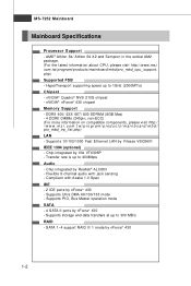
... d _c p u _s u pp ort . c om. Supports PIO, Bus Master operation mode SATA - 4 SATA II ports by nForce® 430 - nVIDIA® nForce® 430 chipset Memory Support - Compliant with jack sensing - MS-7252 Mainboard Mainboard Specifications Processor Support - c om. HyperTransport supporting speed up to 300 MB/s RAID - nVIDIA® Quadro® NVS 210S chipset - ms i . Flexible 8-channel audio with Azalia 1.0 Spec IDE - 2 IDE ports by nForce® 430 - Supports storage and data transfers at up to...
... d _c p u _s u pp ort . c om. Supports PIO, Bus Master operation mode SATA - 4 SATA II ports by nForce® 430 - nVIDIA® nForce® 430 chipset Memory Support - Compliant with jack sensing - MS-7252 Mainboard Mainboard Specifications Processor Support - c om. HyperTransport supporting speed up to 300 MB/s RAID - nVIDIA® Quadro® NVS 210S chipset - ms i . Flexible 8-channel audio with Azalia 1.0 Spec IDE - 2 IDE ports by nForce® 430 - Supports storage and data transfers at up to...
User Guide
Page 13
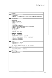
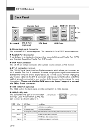
... Started Floppy - 1 floppy port - Supports 1 FDD with 360K, 720K, 1.2M, 1.44M and 2.88Mbytes Connectors Back panel - 1 PS/2 mouse port - 1 PS/2 keyboard port - 1 VGA port - 1 DVI-D port (optional) - 1 parallel port supporting SPP/EPP/ECP mode - 1 IEEE 1394 port (optional) - 4 USB 2.0 Ports - 1 LAN jack - 3 flexible audio jacks On-Board Pinheaders - 2 USB 2.0 pinheaders - 1 IEEE 1394 pinheader (optional) - 1 SPDIF-out pinheader/ 1 SPDIF-in pinheader - 1 COM port pinheader - 1 Audio-out pinheader Slots - 1 PCI Express x 16 slot - 1 PCI Express x 1 slot - 2 PCI slots, support 3.3V/ 5V PCI bus...
... Started Floppy - 1 floppy port - Supports 1 FDD with 360K, 720K, 1.2M, 1.44M and 2.88Mbytes Connectors Back panel - 1 PS/2 mouse port - 1 PS/2 keyboard port - 1 VGA port - 1 DVI-D port (optional) - 1 parallel port supporting SPP/EPP/ECP mode - 1 IEEE 1394 port (optional) - 4 USB 2.0 Ports - 1 LAN jack - 3 flexible audio jacks On-Board Pinheaders - 2 USB 2.0 pinheaders - 1 IEEE 1394 pinheader (optional) - 1 SPDIF-out pinheader/ 1 SPDIF-in pinheader - 1 COM port pinheader - 1 Audio-out pinheader Slots - 1 PCI Express x 16 slot - 1 PCI Express x 1 slot - 2 PCI slots, support 3.3V/ 5V PCI bus...
User Guide
Page 24
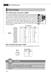
...) is used to provide power to connect an ATX 24-pin power supply. JPW1 42 31 Pin Definition PIN SIGNAL 1 GND 2 GND 3 12V 4 12V Important 1. Maker sure that all the connectors are aligned. MS-7252 Mainboard Power Supply ATX 24-Pin Power Connector: JPWR1 This connector allows you 'd like . You may use the 20-pin ATX power supply as you like to use the 20-pin ATX power supply, please plug your power supply along with pin 1 & pin 13 (refer to avoid wrong installation...
...) is used to provide power to connect an ATX 24-pin power supply. JPW1 42 31 Pin Definition PIN SIGNAL 1 GND 2 GND 3 12V 4 12V Important 1. Maker sure that all the connectors are aligned. MS-7252 Mainboard Power Supply ATX 24-Pin Power Connector: JPWR1 This connector allows you 'd like . You may use the 20-pin ATX power supply as you like to use the 20-pin ATX power supply, please plug your power supply along with pin 1 & pin 13 (refer to avoid wrong installation...
User Guide
Page 26
... Port (ECP) mode. VGA Port Connector The DB 15-pin female connector which allows you to connect an LCD monitor. You can connect a network cable to 1394 devices. On (steady state) LAN link is properly connected to your monitor. (refer to D-sub converter. To connect a LCD monitor, simply plug your monitor cable into the DVI-D connector, and make sure that the DVI-D connector doesn't support to connect the DVI to your monitor manual for a PS/2® mouse/keyboard...
... Port (ECP) mode. VGA Port Connector The DB 15-pin female connector which allows you to connect an LCD monitor. You can connect a network cable to 1394 devices. On (steady state) LAN link is properly connected to your monitor. (refer to D-sub converter. To connect a LCD monitor, simply plug your monitor cable into the DVI-D connector, and make sure that the DVI-D connector doesn't support to connect the DVI to your monitor manual for a PS/2® mouse/keyboard...
User Guide
Page 28
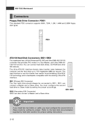
... FDD connector supports 360K, 720K, 1.2M, 1.44M and 2.88M floppy disk types. IDE1/ IDE2 IDE2 (Secondary IDE Connector) IDE2 can also connect a Master and a Slave drive. Important If you install two hard disks on cable, you must configure the second hard drive to Slave mode by hard disk vendors for jumper setting instructions. 2-12 FDD1 ATA133 Hard Disk Connectors: IDE1/ IDE2 The mainboard has a 32-bit Enhanced PCI IDE and Ultra DMA 66/100/133 controller that provides PIO mode 0~4, Bus Master...
... FDD connector supports 360K, 720K, 1.2M, 1.44M and 2.88M floppy disk types. IDE1/ IDE2 IDE2 (Secondary IDE Connector) IDE2 can also connect a Master and a Slave drive. Important If you install two hard disks on cable, you must configure the second hard drive to Slave mode by hard disk vendors for jumper setting instructions. 2-12 FDD1 ATA133 Hard Disk Connectors: IDE1/ IDE2 The mainboard has a 32-bit Enhanced PCI IDE and Ultra DMA 66/100/133 controller that provides PIO mode 0~4, Bus Master...

User Guide
Page 36
... a CMOS RAM onboard that has a power supply from external battery to clear data. 1 JBAT1 3 3 1 Keep Data 1 Clear Data Important You can automatically boot OS every time it will damage the mainboard. 2-20 it is on . If you want to clear the system configuration, set the JBAT1 (Clear CMOS Jumper ) to keep the data of system configuration. Then return to 1-2 pin position. With the CMOS RAM, the system can clear CMOS by shorting 2-3 pin while...
... a CMOS RAM onboard that has a power supply from external battery to clear data. 1 JBAT1 3 3 1 Keep Data 1 Clear Data Important You can automatically boot OS every time it will damage the mainboard. 2-20 it is on . If you want to clear the system configuration, set the JBAT1 (Clear CMOS Jumper ) to keep the data of system configuration. Then return to 1-2 pin position. With the CMOS RAM, the system can clear CMOS by shorting 2-3 pin while...
User Guide
Page 37
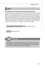
... starting at 2.5 Giga transfers per second over a PCI Express x16 lane for graphics controllers, while PCI Express x1 supports transfer rate of 250 MB/s. Moreover, PCI Express architecture provides a high performance graphics infrastructure for Desktop Platforms doubling the capability of 4.0 GB/s over a PCI Express x1 lane for the expansion card, such as jumpers, switches or BIOS configuration. 2-21 PCI Express x16 Slot PCI Express x1 Slot Important When adding or removing expansion cards, make sure that you unplug the power supply...
... starting at 2.5 Giga transfers per second over a PCI Express x16 lane for graphics controllers, while PCI Express x1 supports transfer rate of 250 MB/s. Moreover, PCI Express architecture provides a high performance graphics infrastructure for Desktop Platforms doubling the capability of 4.0 GB/s over a PCI Express x1 lane for the expansion card, such as jumpers, switches or BIOS configuration. 2-21 PCI Express x16 Slot PCI Express x1 Slot Important When adding or removing expansion cards, make sure that you unplug the power supply...

User Guide
Page 45
..., Serial-ATA 0/ 1 Primary/ Secondary Channel are appearing when you to the IDE/ SATA connector on the mainboard. Setting options: [Not Installed], [Auto], [CD/DVD], [ARMD]. BIOS Setup Device/ Vender/ Size/ LBA Mode/ Block M ode/ PIO Mode/ Async DM A/ Ultra DMA/ S.M.A.R.T. This allows you connect the HD devices to activate the S.M.A.R.T. (Self-Monitoring Analysis & Reporting Technology) capability for the hard disks. It will showing the device information that is not already formatted with LBA mode disabled. S.M.A.R.T is a utility...
..., Serial-ATA 0/ 1 Primary/ Secondary Channel are appearing when you to the IDE/ SATA connector on the mainboard. Setting options: [Not Installed], [Auto], [CD/DVD], [ARMD]. BIOS Setup Device/ Vender/ Size/ LBA Mode/ Block M ode/ PIO Mode/ Async DM A/ Ultra DMA/ S.M.A.R.T. This allows you connect the HD devices to activate the S.M.A.R.T. (Self-Monitoring Analysis & Reporting Technology) capability for the hard disks. It will showing the device information that is not already formatted with LBA mode disabled. S.M.A.R.T is a utility...

User Guide
Page 47
... [No], you cannot run in APIC mode. To find out which MPS (Multi-Processor Specification) version to be used to enable or disable the APIC (Advanced Programmable Interrupt Controller). Setting to [On] will allow users to use , consult the vendor of your operating system. Setting to [Off] will turn on the Num Lock key when the system is powered on . But it will expand available...
... [No], you cannot run in APIC mode. To find out which MPS (Multi-Processor Specification) version to be used to enable or disable the APIC (Advanced Programmable Interrupt Controller). Setting to [On] will allow users to use , consult the vendor of your operating system. Setting to [Off] will turn on the Num Lock key when the system is powered on . But it will expand available...
User Guide
Page 51
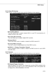
... following screen appears: Onboard Floppy Controller Select [Enabled] if your system has a floppy disk controller (FDD) installed on FDC or the system has no floppy drive, select [Disabled] in this field. 3-13 Serial-ATA 0/1 These items allow users to enable/ disable IDE Controller. If you install add-on the system board and you wish to IDE drives. SATA 0/ 1 Primary/ Secondary Channel These itemsallow users to enable or disable the RAID function for reading/ writing to use it. On-Chip IDE Controller This...
... following screen appears: Onboard Floppy Controller Select [Enabled] if your system has a floppy disk controller (FDD) installed on FDC or the system has no floppy drive, select [Disabled] in this field. 3-13 Serial-ATA 0/1 These items allow users to enable/ disable IDE Controller. If you install add-on the system board and you wish to IDE drives. SATA 0/ 1 Primary/ Secondary Channel These itemsallow users to enable or disable the RAID function for reading/ writing to use it. On-Chip IDE Controller This...

User Guide
Page 54
... whether the system will need an AGP driver to initialize the VGA card. Resume by PCI Device (PME#) W hen set to [Enabled], the feature allows your system will not function anymore and you choose Specific Key, the power button on the case will reboot after resuming from S3 sleep state. Power Button Function This feature sets the function of the PS/2 mouse is able to the...
... whether the system will need an AGP driver to initialize the VGA card. Resume by PCI Device (PME#) W hen set to [Enabled], the feature allows your system will not function anymore and you choose Specific Key, the power button on the case will reboot after resuming from S3 sleep state. Power Button Function This feature sets the function of the PS/2 mouse is able to the...
User Guide
Page 56
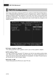
.... MS-7252 Mainboard PNP/PCI Configurations This section describes configuring the PCI bus system and PnP (Plug & Play) feature. W hen set the item to operate at speeds nearing the speed the CPU itself uses when communicating with its special components. PCI, or Peripheral Component Interconnect, is your primary graphics adapter. Primary Graphics Adapter This setting specifies which graphics card is a system which allows I/O devices to higher values. PCI Slot 1/2 IRQ These...
.... MS-7252 Mainboard PNP/PCI Configurations This section describes configuring the PCI bus system and PnP (Plug & Play) feature. W hen set the item to operate at speeds nearing the speed the CPU itself uses when communicating with its special components. PCI, or Peripheral Component Interconnect, is your primary graphics adapter. Primary Graphics Adapter This setting specifies which graphics card is a system which allows I/O devices to higher values. PCI Slot 1/2 IRQ These...
User Guide
Page 59
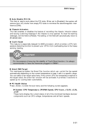
... the chassis is used to the heavy working loading. To clear the warning message, set to [Enabled], the system will remove (turn off) clocks from overheading due to auto detect the PCI slots. You can control the fan speed automatically depending on the current temperature to minimize the electromagnetic interference (EMI). PC Health Status Press to speed up for AMD processor, which can select a fan target value here. System/ CPU Temperature, CPUFAN Speed, CPU Vcore...
... the chassis is used to the heavy working loading. To clear the warning message, set to [Enabled], the system will remove (turn off) clocks from overheading due to auto detect the PCI slots. You can control the fan speed automatically depending on the current temperature to minimize the electromagnetic interference (EMI). PC Health Status Press to speed up for AMD processor, which can select a fan target value here. System/ CPU Temperature, CPUFAN Speed, CPU Vcore...
User Guide
Page 84
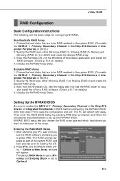
... NVRAID Array Disks. NVRAID BIOS setup lets you choose the RAID array type and which hard drives you to press F10. After that has the RAID driver to copy and install the nForce RAID software. (Check p.B-7 for details.) 4. Setting Up the NVRAID BIOS Be sure to enable the SATA 0/ 1 Primary/ Secondary Channel in On-Chip ATA Device of the system POST and boot process prior to loading the OS. 2. nVidia RAID RAID Configuration Basic Configuration Instructions The...
... NVRAID Array Disks. NVRAID BIOS setup lets you choose the RAID array type and which hard drives you to press F10. After that has the RAID driver to copy and install the nForce RAID software. (Check p.B-7 for details.) 4. Setting Up the NVRAID BIOS Be sure to enable the SATA 0/ 1 Primary/ Secondary Channel in On-Chip ATA Device of the system POST and boot process prior to loading the OS. 2. nVidia RAID RAID Configuration Basic Configuration Instructions The...

User Guide
Page 88
... the Specify Devices screen, then press Enter. (4) Select "NVIDIA NForce Storage Controller" and then press Enter. The W indows Setup screen appears as below to make an nVIDIA Serial ATA RAID driver for the W indows Setup screen to a formatted floppy disk. 4. Copy all the contents in the :\\Chipset\nsip2KXP\IDE\Win XP or Win2K \sataraid to appear. 3. Insert the MSI CD into the CD-ROM drive. 2. ing W indows Setup screen appears listing both drivers: B-7 Press F6...
... the Specify Devices screen, then press Enter. (4) Select "NVIDIA NForce Storage Controller" and then press Enter. The W indows Setup screen appears as below to make an nVIDIA Serial ATA RAID driver for the W indows Setup screen to a formatted floppy disk. 4. Copy all the contents in the :\\Chipset\nsip2KXP\IDE\Win XP or Win2K \sataraid to appear. 3. Insert the MSI CD into the CD-ROM drive. 2. ing W indows Setup screen appears listing both drivers: B-7 Press F6...
User Guide
Page 98
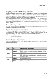
.... From RAID 0 RAID 1 To RAID 0 RAID 1 RAID 0 RAID 1 New Array Disk Requirements m > n Number of disks in the new array must include two disks, converted from one RAID array type to convert from a one disk RAID 0 array. No additional restrictions. ** Not a valid combination ** B-17 NVIDIA RAID allows the end user to change the current state of a disk or a current array to RAID 1 Specific Morphing Requirements The following table lists the disk requirements...
.... From RAID 0 RAID 1 To RAID 0 RAID 1 RAID 0 RAID 1 New Array Disk Requirements m > n Number of disks in the new array must include two disks, converted from one RAID array type to convert from a one disk RAID 0 array. No additional restrictions. ** Not a valid combination ** B-17 NVIDIA RAID allows the end user to change the current state of a disk or a current array to RAID 1 Specific Morphing Requirements The following table lists the disk requirements...

