

User Guide
Page 2
....tw/program/service/faq/ faq/esc_faq_list.php Contact our technical staff at: http://support.msi.com.tw/ ii Award® is a registered trademark of American Megatrends Inc. Visit the MSI website for further guidance. AMD, Athlon™, Athlon™ XP, Thoroughbred™, and ...contents. Intel® and Pentium® are registered trademarks of Novell, Inc. Revision History Revision V1.1 Revision History First release for K9NBPM2-FID Date September 2006 Technical Support If a problem arises with your place of M ICRO-STAR INTERNATIONAL. Netware® is given as...
....tw/program/service/faq/ faq/esc_faq_list.php Contact our technical staff at: http://support.msi.com.tw/ ii Award® is a registered trademark of American Megatrends Inc. Visit the MSI website for further guidance. AMD, Athlon™, Athlon™ XP, Thoroughbred™, and ...contents. Intel® and Pentium® are registered trademarks of Novell, Inc. Revision History Revision V1.1 Revision History First release for K9NBPM2-FID Date September 2006 Technical Support If a problem arises with your place of M ICRO-STAR INTERNATIONAL. Netware® is given as...

User Guide
Page 3
Keep this equipment on the equipment should be - ment from humidity. 4. Place the power cord such a way that could damage or cause electrical s h oc k . 11. iii Replac e only with the same or equivalent type rec ommended by a service personnel: † The power cord or plug is damaged. † Liquid has penetrated into the opening that people can not get it up. 5. Make sure the voltage of expl os i on card or module. 9. Always read the safety instructions carefully. 2. DO NOT COVER THE OPENINGS. 6. Keep this equipment away from overheating. The openings ...
Keep this equipment on the equipment should be - ment from humidity. 4. Place the power cord such a way that could damage or cause electrical s h oc k . 11. iii Replac e only with the same or equivalent type rec ommended by a service personnel: † The power cord or plug is damaged. † Liquid has penetrated into the opening that people can not get it up. 5. Make sure the voltage of expl os i on card or module. 9. Always read the safety instructions carefully. 2. DO NOT COVER THE OPENINGS. 6. Keep this equipment away from overheating. The openings ...

User Guide
Page 4
If this device must be determined by turning the equipment off and on, the user is encouraged to try to correct the interference by the party responsible for compliance could void the user's authority to operate the equipment. Notice 2 Shielded interface cables and A.C. FCC-B Radio Frequency Interference Statement T h is eq uip men t h as been tested and found to comply with the limits for a Class B digital device, pursuant to Part 15 of the FCC Rules. However, there is connected. † Consult the dealer or an experienced radio/television technician for help. power cord, if ...
If this device must be determined by turning the equipment off and on, the user is encouraged to try to correct the interference by the party responsible for compliance could void the user's authority to operate the equipment. Notice 2 Shielded interface cables and A.C. FCC-B Radio Frequency Interference Statement T h is eq uip men t h as been tested and found to comply with the limits for a Class B digital device, pursuant to Part 15 of the FCC Rules. However, there is connected. † Consult the dealer or an experienced radio/television technician for help. power cord, if ...

User Guide
Page 5
WEEE (Waste Electrical and Electronic Equipment) Statement v
WEEE (Waste Electrical and Electronic Equipment) Statement v

User Guide
Page 8
... Safety Instructions ...iii FCC-B Radio Frequency Interference Statement iv W EEE (Waste Electrical and Electronic Equipment) Statement v Chapter 1 Getting Started 1.1 Mainboard Specifications 1-2 Mainboard Layout 1-4 Packing Checklist 1-5 MSI Special Feature 1-6 Chapter 2 Hardware Setup 2-1 Quick Components Guide 2-2 CPU (Central Processing Unit 2-3 CPU Installation Procedures for Socket AM2 2-4 Installing AMD Socket AM2 CPU Cooler Set...
... Safety Instructions ...iii FCC-B Radio Frequency Interference Statement iv W EEE (Waste Electrical and Electronic Equipment) Statement v Chapter 1 Getting Started 1.1 Mainboard Specifications 1-2 Mainboard Layout 1-4 Packing Checklist 1-5 MSI Special Feature 1-6 Chapter 2 Hardware Setup 2-1 Quick Components Guide 2-2 CPU (Central Processing Unit 2-3 CPU Installation Procedures for Socket AM2 2-4 Installing AMD Socket AM2 CPU Cooler Set...
User Guide
Page 9
Audio-out Connector: J1 2-18 Front Panel Connectors: JFP1/JFP2 2-19 Jumper ...2-20 Clear CMOS Jumper: JBAT1 2-20 Slots ...2-21 PCI (Peripheral Component Interconnect) Express Slots 2-21 PCI (Peripheral Component Interconnect) Slots 2-22 PCI Interrupt Request Routing 2-22 Chapter 3 BIOS Setup 3-1 Entering Setup ...3-2 Control Keys 3-3 Getting Help 3-3 General Help
Audio-out Connector: J1 2-18 Front Panel Connectors: JFP1/JFP2 2-19 Jumper ...2-20 Clear CMOS Jumper: JBAT1 2-20 Slots ...2-21 PCI (Peripheral Component Interconnect) Express Slots 2-21 PCI (Peripheral Component Interconnect) Slots 2-22 PCI Interrupt Request Routing 2-22 Chapter 3 BIOS Setup 3-1 Entering Setup ...3-2 Control Keys 3-3 Getting Help 3-3 General Help

User Guide
Page 10
Setting Up the NVRAID BIOS B-3 Installing the RAID Driver (for bootable RAID Array B-7 NVIDIA IDE Driver/ RAID Utility Installation B-9 Installing the NVIDIA RAID Software Under Windows (for Non-bootable RAID Arr ay) ...B-9 Initializing and Using the Disk Array B-10 NVRAID Management Utility B-12 Viewing RAID Array Configurations B-12 Setting Up a Spare RAID Disk B-13 Morphing From One RAID Array to Another B-17 Hot Plug Array B-18 Initializing a RAID Array B-19 Rebuilding a RAID Array B-22 Synchronizing a RAID Array B-25 Appendix C nVidia System Driver C-1 nVidia System Driver ...
Setting Up the NVRAID BIOS B-3 Installing the RAID Driver (for bootable RAID Array B-7 NVIDIA IDE Driver/ RAID Utility Installation B-9 Installing the NVIDIA RAID Software Under Windows (for Non-bootable RAID Arr ay) ...B-9 Initializing and Using the Disk Array B-10 NVRAID Management Utility B-12 Viewing RAID Array Configurations B-12 Setting Up a Spare RAID Disk B-13 Morphing From One RAID Array to Another B-17 Hot Plug Array B-18 Initializing a RAID Array B-19 Rebuilding a RAID Array B-22 Synchronizing a RAID Array B-25 Appendix C nVidia System Driver C-1 nVidia System Driver ...
User Guide
Page 11
Designed to fit the advanced AMD® Athlon 64/ X2/ Sempron processor, the K9NBPM2-FID Series deliver a high performance and professional desktop platform solution. 1-1 Getting Started Chapter 1 Getting Started Thank you for optimal system efficiency. The K9NBPM2-FID Series mainboards are based on nVidia® Quadro® NVS 210S & nVidia® nForce® 430 chipsets for choosing the K9NBPM2-FID Series (MS7252 v1.X) Micro ATX mainboard.
Designed to fit the advanced AMD® Athlon 64/ X2/ Sempron processor, the K9NBPM2-FID Series deliver a high performance and professional desktop platform solution. 1-1 Getting Started Chapter 1 Getting Started Thank you for optimal system efficiency. The K9NBPM2-FID Series mainboards are based on nVidia® Quadro® NVS 210S & nVidia® nForce® 430 chipsets for choosing the K9NBPM2-FID Series (MS7252 v1.X) Micro ATX mainboard.
User Guide
Page 12
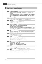
... Vitesse VSC8601 IEEE 1394 (optional) - t w / pr og ra m/ p r od u c t s / ma in the socket AM2 package. (For the latest information about CPU, please visit http://www.msi. ms i . Supports 10/100/1000 Fast Ethernet LAN by Realtek® ALC883 - Supports PIO, Bus Master operation mode SATA - 4 SATA II ports by VIA VT6308P...
... Vitesse VSC8601 IEEE 1394 (optional) - t w / pr og ra m/ p r od u c t s / ma in the socket AM2 package. (For the latest information about CPU, please visit http://www.msi. ms i . Supports 10/100/1000 Fast Ethernet LAN by Realtek® ALC883 - Supports PIO, Bus Master operation mode SATA - 4 SATA II ports by VIA VT6308P...
User Guide
Page 13
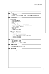
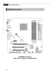
Micro-ATX (24.4 cm X 24.4 cm) Mounting - 8 mounting holes 1-3 Supports 1 FDD with 360K, 720K, 1.2M, 1.44M and 2.88Mbytes Connectors Back panel - 1 PS/2 mouse port - 1 PS/2 keyboard port - 1 VGA port - 1 DVI-D port (optional) - 1 parallel port supporting SPP/EPP/ECP mode - 1 IEEE 1394 port (optional) - 4 USB 2.0 Ports - 1 LAN jack - 3 flexible audio jacks On-Board Pinheaders - 2 USB 2.0 pinheaders - 1 IEEE 1394 pinheader (optional) - 1 SPDIF-out pinheader/ 1 SPDIF-in pinheader - 1 COM port pinheader - 1 Audio-out pinheader Slots - 1 PCI Express x 16 slot - 1 PCI Express x 1 slot - 2 PCI ...
Micro-ATX (24.4 cm X 24.4 cm) Mounting - 8 mounting holes 1-3 Supports 1 FDD with 360K, 720K, 1.2M, 1.44M and 2.88Mbytes Connectors Back panel - 1 PS/2 mouse port - 1 PS/2 keyboard port - 1 VGA port - 1 DVI-D port (optional) - 1 parallel port supporting SPP/EPP/ECP mode - 1 IEEE 1394 port (optional) - 4 USB 2.0 Ports - 1 LAN jack - 3 flexible audio jacks On-Board Pinheaders - 2 USB 2.0 pinheaders - 1 IEEE 1394 pinheader (optional) - 1 SPDIF-out pinheader/ 1 SPDIF-in pinheader - 1 COM port pinheader - 1 Audio-out pinheader Slots - 1 PCI Express x 16 slot - 1 PCI Express x 1 slot - 2 PCI ...
User Guide
Page 14
... di a nForce 430 ALC883 JAUD1 JCD1 PCI2 BIOS JSPDO1 JSPDI1 J1 J13 94_1 (optional) JCOM1 JUSB1 JUSB2 DIMM1 DIMM2 DIMM3 DIMM4 SATA3 SATA4 IDE 2 JFP1 K9NBPM2-FID Series (MS-7252 v1.X) Micro-ATX Mainboard IDE 1 S Y S FA N 1 SATA1 SATA2 JBAT1 J FP2 1-4
... di a nForce 430 ALC883 JAUD1 JCD1 PCI2 BIOS JSPDO1 JSPDI1 J1 J13 94_1 (optional) JCOM1 JUSB1 JUSB2 DIMM1 DIMM2 DIMM3 DIMM4 SATA3 SATA4 IDE 2 JFP1 K9NBPM2-FID Series (MS-7252 v1.X) Micro-ATX Mainboard IDE 1 S Y S FA N 1 SATA1 SATA2 JBAT1 J FP2 1-4

User Guide
Page 15
Packing Checklist Getting Started MSI motherboard MSI Driver/Utility CD Standard Cable for IDE Devices Power Cable SATA Cable Back IO Shield User's Guide * The pictures are for reference only and may vary from the packing contents of the product you purchased. 1-5
Packing Checklist Getting Started MSI motherboard MSI Driver/Utility CD Standard Cable for IDE Devices Power Cable SATA Cable Back IO Shield User's Guide * The pictures are for reference only and may vary from the packing contents of the product you purchased. 1-5

User Guide
Page 16
... abnormal item highlighted in the CD-ROM disk. Click Temperature to send out a warning message. This will show the current CPU temperature. 1-6 MS-7252 Mainboard MSI Special Feature PC Alert™ 4 The PC AlertTM 4 is abnormal, the program main screen will be immediately shown on the Status Area will continue to...
... abnormal item highlighted in the CD-ROM disk. Click Temperature to send out a warning message. This will show the current CPU temperature. 1-6 MS-7252 Mainboard MSI Special Feature PC Alert™ 4 The PC AlertTM 4 is abnormal, the program main screen will be immediately shown on the Status Area will continue to...

User Guide
Page 17
Use a grounded wrist strap before handling computer components. While doing the installation, be careful in the wrong orientation, the components will not work properly. For some components, if you with the information about hardware setup procedures. Static electricity may damage the components. 2-1 Hardware Setup Chapter 2 Hardware Setup This chapter provides you install in holding the components and follow the installation procedures.
Use a grounded wrist strap before handling computer components. While doing the installation, be careful in the wrong orientation, the components will not work properly. For some components, if you with the information about hardware setup procedures. Static electricity may damage the components. 2-1 Hardware Setup Chapter 2 Hardware Setup This chapter provides you install in holding the components and follow the installation procedures.

User Guide
Page 19
Make sure that you apply an even layer of CPU. 2-3 For the latest information about CPU, please visit http://www.msi.com.tw/program/ products/mainboard/mbd/pro_mbd_cpu_support.php. Important 1. Always make sure the CPU has a heat sink and a cooling fan attached on the computer. W hen ...
Make sure that you apply an even layer of CPU. 2-3 For the latest information about CPU, please visit http://www.msi.com.tw/program/ products/mainboard/mbd/pro_mbd_cpu_support.php. Important 1. Always make sure the CPU has a heat sink and a cooling fan attached on the computer. W hen ...

User Guide
Page 20
Please turn off the power and unplug the power cord before installing the CPU. 2. Sliding Plate Open Lever 90 degree 3. The gold arrow should be completely embedded into the socket and can only fit in the picture. Make sure to raise the lever up to move while the lever is being closed, always close the lever. If the CPU is properly and completely embedded into the socket and close the lever with your mainboard. Gold arrow Gold arrow Correct CPU placement O 5. Pull the lever sideways away from the socket. Press the CPU down firmly into the socket. 2-4 Look for Socket...
Please turn off the power and unplug the power cord before installing the CPU. 2. Sliding Plate Open Lever 90 degree 3. The gold arrow should be completely embedded into the socket and can only fit in the picture. Make sure to raise the lever up to move while the lever is being closed, always close the lever. If the CPU is properly and completely embedded into the socket and close the lever with your mainboard. Gold arrow Gold arrow Correct CPU placement O 5. Pull the lever sideways away from the socket. Press the CPU down firmly into the socket. 2-4 Look for Socket...

User Guide
Page 21
Important Mainboard photos shown in this section are installing the CPU, make sure the CPU has a heat sink and a cooling fan attached on the top to purchase and install them before turning on the computer. Then press down the lever. 4. Hook one end of the clip to fasten the cooling set onto the retention mechanism. Fixed Lever 3. Fasten down the other end of the clip to hook first. 2. The appearance of your dealer to prevent overheating. Locate the Fix Lever and lift up it . Hardware Setup Installing AMD Socket AM2 CPU Cooler Set W hen you are for demonstration of the cooler...
Important Mainboard photos shown in this section are installing the CPU, make sure the CPU has a heat sink and a cooling fan attached on the top to purchase and install them before turning on the computer. Then press down the lever. 4. Hook one end of the clip to fasten the cooling set onto the retention mechanism. Fixed Lever 3. Fasten down the other end of the clip to hook first. 2. The appearance of your dealer to prevent overheating. Locate the Fix Lever and lift up it . Hardware Setup Installing AMD Socket AM2 CPU Cooler Set W hen you are for demonstration of the cooler...

User Guide
Page 22
ph p DDRII 240-pin, 1.8V 56x2=112 pin 64x2=128 pin Dual-Channel Memory Population Rules 1 DIMM1 DIMM2 DIMM3 DIMM4 2 DIMM1 DIMM2 DIMM3 DIMM4 3 DIMM1 DIMM2 DIMM3 DIMM4 2-6 MS-7252 Mainboard Memory The mainboard provides four 240-pin non-ECC DDRII DIMMs and supports up to 8 GB system memory. For more information on compatible components, please visit http://www.msi.com.tw/ p ro gr a m/ pr o du c t s /m ain bo ar d /m bd / pr o_ m bd _t r p_ lis t.
ph p DDRII 240-pin, 1.8V 56x2=112 pin 64x2=128 pin Dual-Channel Memory Population Rules 1 DIMM1 DIMM2 DIMM3 DIMM4 2 DIMM1 DIMM2 DIMM3 DIMM4 3 DIMM1 DIMM2 DIMM3 DIMM4 2-6 MS-7252 Mainboard Memory The mainboard provides four 240-pin non-ECC DDRII DIMMs and supports up to 8 GB system memory. For more information on compatible components, please visit http://www.msi.com.tw/ p ro gr a m/ pr o du c t s /m ain bo ar d /m bd / pr o_ m bd _t r p_ lis t.

User Guide
Page 23
Then push it in until the golden finger on the center and will only fit in the right orientation. 2. Due to 7+GB (not full 8 GB) when each side of the same type and density in the DIMM slot. Important You can barely see the golden finger if the module is not backwards compatible. To enable successful system boot-up to the chipset resource deployment, the system density will automatically close. The plastic clip at each DIMM is deeply inserted in different channel DDR DIMMs. - In dual-channel mode, make sure that you install memory modules of the DIMM slot will only ...
Then push it in until the golden finger on the center and will only fit in the right orientation. 2. Due to 7+GB (not full 8 GB) when each side of the same type and density in the DIMM slot. Important You can barely see the golden finger if the module is not backwards compatible. To enable successful system boot-up to the chipset resource deployment, the system density will automatically close. The plastic clip at each DIMM is deeply inserted in different channel DDR DIMMs. - In dual-channel mode, make sure that you install memory modules of the DIMM slot will only ...
User Guide
Page 24
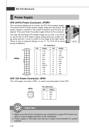
You may use the 20-pin ATX power supply, please plug your power supply along with pin 1 & pin 13 (refer to the image at the right hand). Power supply of the mainboard. 2. Then push down the power supply firmly into the connector. If you'd like . There is highly recommended for system stability. 2-8 Maker sure that all the connectors are aligned. JPW1 42 31 Pin Definition PIN SIGNAL 1 GND 2 GND 3 12V 4 12V Important 1. To connect the ATX 24-pin power supply, make sure the plug of the power supply is used to provide power to ensure stable operation of 350 watts (and above)...
You may use the 20-pin ATX power supply, please plug your power supply along with pin 1 & pin 13 (refer to the image at the right hand). Power supply of the mainboard. 2. Then push down the power supply firmly into the connector. If you'd like . There is highly recommended for system stability. 2-8 Maker sure that all the connectors are aligned. JPW1 42 31 Pin Definition PIN SIGNAL 1 GND 2 GND 3 12V 4 12V Important 1. To connect the ATX 24-pin power supply, make sure the plug of the power supply is used to provide power to ensure stable operation of 350 watts (and above)...